Article

Holographic Tailoring of Structured Light Field with Digital Device

1
Key Laboratory of Photonic Control Technology, Tsinghua University, Ministry of Education, Beijing 100084, China
2
State Key Laboratory of Precision Measurement Technology and Instruments, Department of Precision Instrument, Tsinghua University, Beijing 100084, China
*
Author to whom correspondence should be addressed.
Photonics 2022, 9(7), 506; https://doi.org/10.3390/photonics9070506
Submission received: 22 June 2022 / Revised: 14 July 2022 / Accepted: 19 July 2022 / Published: 21 July 2022
(This article belongs to the Special Issue Vortex Beams: Fundamentals and Applications)

Abstract

:
Structured light fields have attracted much attention due to rich spatial degrees of freedom. The tailoring of an arbitrary structured light field on demand is the precondition for the application of structured light. Therefore, the computer holography method used to reconstruct a coherent light field wavefront has been naturally applied for generating structured light. In this work, we comprehensively demonstrate the principles and procedures of pure-phase computer-generated holography (PP-CGH) and binary-amplitude computer-generated holography (BA-CGH) methods for tailoring structured light, realized by two digitally programmable devices: liquid-crystal spatial light modulators ( Lc - SLM ) and digital micromirror devices (DMD), respectively. Moreover, we first compare the two approaches in detail and clarify the recipe to obtain a high tailoring accuracy and efficiency, which will help researchers to better understand and utilize the holographic tailoring of structured optical fields.

1. Introduction

The spatial structure of light is a very important manipulation dimension of an optical field, along with other physical degrees of freedom, such as time, amplitude, wavelength (frequency), polarization and phase [1,2,3]. Thirty years ago, L. Allen pointed out that vortex light beams carrying optical orbital angular momentum (OAM) led to a connection between the OAM in quantum optics and the helical phase of the beam in physical optics [4]. The feature of optical OAM has attracted intense research on vortex beams [5,6], and has triggered a flourish of development in the field of structured light [1,7,8,9,10]. In recent years, structured beams have found important applications in optical communication, optical trapping, imaging, optical sensing, etc. [11,12,13,14]. Those application scenarios, in return, impose increasing highly demands on high-quality, flexible, robust and fast tailoring techniques of structured light.
As a general tool to reconstruct a coherent light field wavefront, the computer holography is naturally applied to tailor structured light fields [15,16,17,18]. Thanks to the recent development of high-resolution, pixelated, programmable commercial spatial light modulators, the combination of computer holography and spatial light modulators has opened up a new and highly efficient route of structured light customization [19,20]. Specifically, the pure-phase computer-generated holography (PP-CGH) and binary-amplitude computer-generated holography (BA-CGH) were implemented in two programmable devices: liquid-crystal spatial light modulators ( Lc - SLM ) and digital micro-mirror devices (DMD), respectively [21,22,23,24]. Various laser modes were created by the CGH method, including the Laguerre–Gaussian beams, Ince–Gaussian beams and non-diffracting beams, as well as cylindrically symmetric vector-vortex beams [24,25,26,27,28]. The CGH methods based on these two digital devices are widely used to tailor structured light due to their high flexibility and excellent tailoring quality.
In this article, we describe the modulation principle and procedure of PP-CGH and BA-CGH methods in detail. In addition, we theoretically analyze the relationship between the tailoring accuracy and number of available pixels by taking vortex light as an example, and point out the optimization route and modulation limit for the use of pixelated modulation devices. Furthermore, to the best of our knowledge, we compare, for the first time, the modulation efficiencies of two methods and clarify the reasons in detail. This work provides a recipe for the tailoring of structured light using the CGH approach.

2. Materials and Methods

The Laguerre–Gaussian (LG) mode family that contains OAM is the most common type of structured beams. We employed LG modes hereinafter to compare the digital CGH methods based on Lc - SLM and DMD. The wave function of LG modes with zero radial index can be indicated as [4,29]:
L G 0 r , z = 2 π ! 1 ω 2 r ω exp r 2 ω 2 exp i ϕ exp i k z + r 2 z 2 z 2 + z R 2 i + 1 θ G o u y
where ω = ω 0 1 + z / z R 2 is radius of Gaussian beam, ω 0 is waist radius, z R = π ω 2 / λ is the Rayleigh length, λ is wavelength, r and ϕ are radial and angular coordinates in the polar coordinate system, respectively, and k = 2 π / λ and θ G o u y = tan 1 z / z R are wavenumber and Gouy phase, respectively. Notably, is the topological charge (TC) of OAM beam, which contributes to the twisted phase. The LG modes have the most concise phase structure at the beam waist ( z = 0 ), which is favorable for the mode tailoring, and can be reduced to:
L G 0 r , 0 = 2 π ! 1 ω 0 2 r ω 0 exp r 2 ω 0 2 exp i ϕ
The intensity and phase pattern of OAM beams at beam waist plane are shown in Figure 1. The sign ‘+’ and ‘−’ of TC () correspond to the phase growth along clockwise and counterclockwise directions, respectively. Moreover, OAM beams with the same have same intensity distribution, and the beam radius is proportional to the square of the beam quality factor.
As a universal tailoring method for scalar structured lights, CGH approach relies on pixelated spatial light modulation device in experiment. The transfer function of PP-CGH hologram for Lc - SLM is given by [22,24]:
T S L M x , y = exp i Ψ A , Φ + 2 π u 0 x + v 0 y = q = c q A exp i q Φ exp i q u 0 x + v 0 y = exp i sin Φ + 2 π u 0 x + v 0 y J 1 1 C A
where A 0 , 1 and Φ 0 , 2 π are normalized amplitude and phase of target structured light field, J 1 1 is inverse of 1 s t Bessel function C 0.681 and u 0 and v 0 are the reciprocals of the linear grating period in x and y directions, respectively.
Similarly, the transfer function of BA-CGH hologram for DMD is given by [23,25]:
T D M D x , y = 1 2 + 1 2 sign cos Φ + 2 π u 0 x + v 0 y + cos arcsin A
Detailed derivations of Equations (3) and (4) can be found in Appendix A and Appendix B. By calculating Equation (3) over a discrete complex amplitude of light field, a phase matrix was obtained whose element corresponds to pixel position on the Lc - SLM screen. Then, a PP-CGH hologram that creates LG beams could be generated. The same applies for binary amplitude matrix of the DMD. The generation procedures of PP-CGH (top row) and BA-CGH (bottom row) of LG 0 10 are shown in Figure 2, which visually demonstrates the calculation process of Equations (3) and (4).
Note that the linear grating 2 π u 0 x + v 0 y in Equations (3) and (4) is used to separate the input light into different orders, as shown in Figure 3a,b. When a planar wave illuminates the PP-CGH or BA-CGH of the target optical field LG 0 10 as inserted in Figure 3c, the far-field of modulated light has multiple spatially separated orders with different patterns, as shown in Figure 3c. By extracting the + 1 order, we obtained the desired LG 0 10 beam, with the simulated results shown in Figure 3d,e for PP-CGH and BA-CGH method, respectively. To avoid the overlapping of target beam and other beams, one can increase the frequency of diffraction grating and thus enlarge the spacing between diffraction orders.

3. Results and Discussion

In order to estimate the generation method of a structured light field, there are two crucial issues to keep in mind. First, one should examine whether the target structured light field can be generated perfectly, and, if not, how to obtain the highest possible tailoring precision. Second, one should check the generation efficiency of a target structured light field and the room for improvement. Hereinafter, we use LG 0 modes as an example to analyze and compare the results of PP-CGH and BA-CGH methods in details.

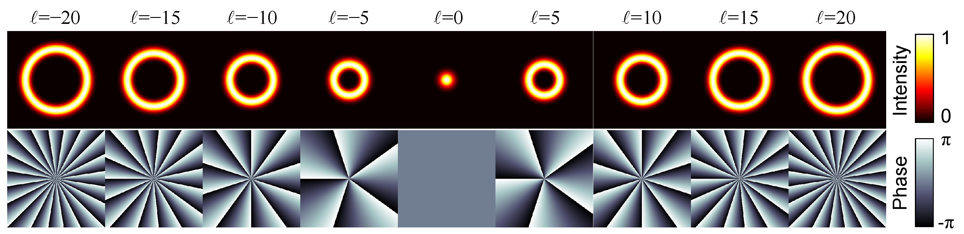
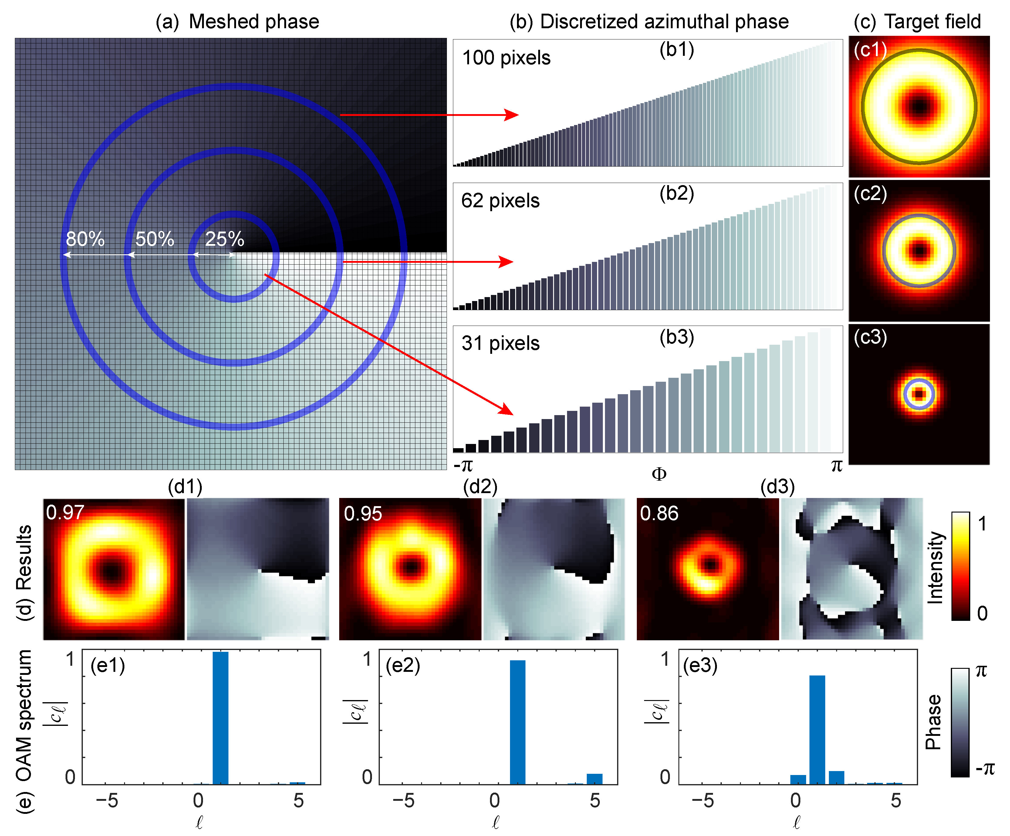
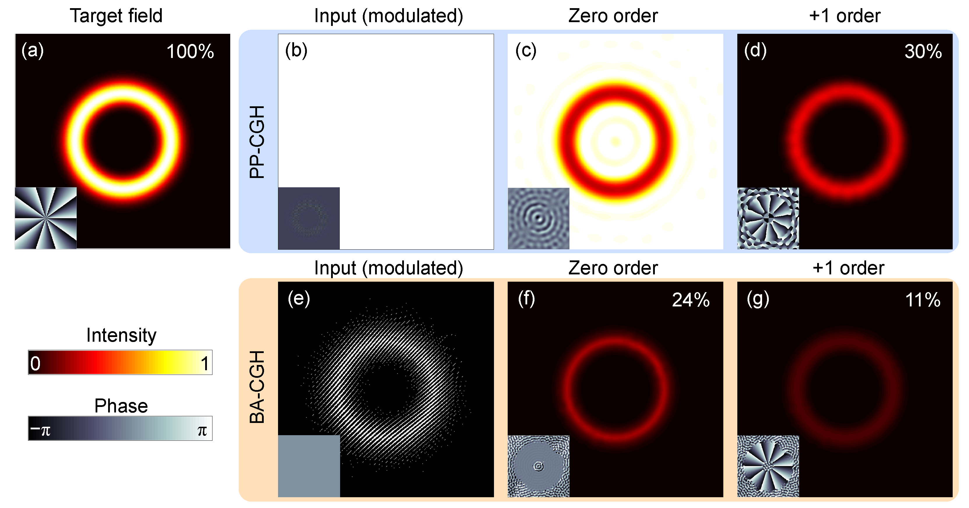
3.1. Precision of Holographic Tailoring

The methods based on BA-CGH and PP-CGH can perfectly tailor arbitrary scalar structured light fields in theory. However, since the DMD and Lc - SLM are pixelated devices, the finite limit of resolution degrades the quality of the reconstructed beam both in the simulation and experiment. The complex amplitude correlation degree between the reconstructed field and theoretical field can be used as an efficient indicator to evaluate the reconstruction quality [30,31], as given by:
γ = E s * x , y E t x , y d x d y E s x , y 2 d x d y E t x , y 2 d x d y
where E t x , y and E s x , y are theoretical and simulated light fields from reconstruction, respectively, and sign ‘*’ means the conjugate. γ = 0 indicates that both fields are orthogonal, whereas γ = 1 indicates that they are identical. γ with a larger value implies a better reconstruction quality.
Importantly, to alleviate the deterioration in reconstruction quality due to a limited resolution, one can increase the number of effectively utilized pixels of the spatial light modulator. Figure 4 illustrates the azimuthal phase discretization of LG 0 1 , and the reconstructed results under different available pixel numbers. The blue circles in Figure 4a mark the sampling regions of a 40 × 40 phase diagram at different radius proportions ( 25 % , 50 % and 80 % ). Figure 4b displays the corresponding discretized azimuthal phase of LG 0 1 , whereas Figure 4c shows the intensity distribution with corresponding radii. Figure 4d shows the reconstructed intensity and phase, with the value of γ shown in the upper left corner of each subfigure. It can be seen that employing a more discretized azimuthal phase—that is, more pixels are utilized in the light field—results in a more accurate reconstruction. The complex amplitude correlation degree of the reconstructed field at 31, 62 and 100 pixels are 0.86, 0.95 and 0.97, respectively. In addition, the OAM spectrum shown in Figure 4e demonstrates that the 80 % aperture has the best performance in suppressing the other TC ( 1 ) components, leading to the least OAM inter-mode crosstalk. For a target light field that is located closer to the coordinate origin, fewer pixels can be utilized, thereby suffering from more severe deterioration in the reconstruction. As such, it is necessary to make full use of available pixels when using the pixelated spatial light modulator.
In addition to resolution, the phase structure of the beam itself also affects the modulation quality. For a phase distribution with a more drastic phase change, a higher resolution is required to reconstruct the light field. We calculated the complex amplitude correlation degree of reconstructed field for nine LG 0 modes [ LG 0 9 , LG 0 17 , LG 0 25 , LG 0 33 , LG 0 41 , LG 0 49 , LG 0 57 , LG 0 65 , LG 0 63 ] in 10 types of resolution settings [40 × 40, 80 × 80, 120 × 120, 160 × 160, 200 × 200, 240 × 240, 280 × 280, 320 × 320, 360 × 360, 400 × 400]. The diameter of the vortex light of different TCs is equal to 50% of the calculated surface size. Therefore, the numbers of available pixels corresponding to different resolutions are 1 × 62 , 2 × 62 , , 9 × 62 and 10 × 62 , respectively. The complex amplitude correlation degree γ in Figure 5 indicates that, as the TC increases, the tailoring accuracy reduces at the same number of pixels, whereas, for the same TC, enlarging the number of available pixels enhances the tailoring accuracy. Note that γ has a nonlinear variation trend versus the number of available pixels utilized. For the case of = 41 , γ is always less than 10 % with the available pixel number below 310, then grows to 62 % at 440 pixels, reaches 83 % at 502 pixels and increases further to 93 % at 565 pixels. Thus, one may need 11, 13 and 14 available pixels in a 2 π phase range to reconstruct the field with the value of γ over 70 % , 80 % and 90 % , respectively. As a result, it is estimated that a vortex beam with TC as high as 300 can be generated with γ > 70 % by fully utilizing a SLM resolution of 1920 × 1080 pixels. In addition, the complex amplitude correlation degrees of PP-CGH and BA-CGH methods are almost the same for all simulated cases, with the average difference less than 1 % . In this regard, two devices are interchangeable when only considering the tailoring quality of the beam field.

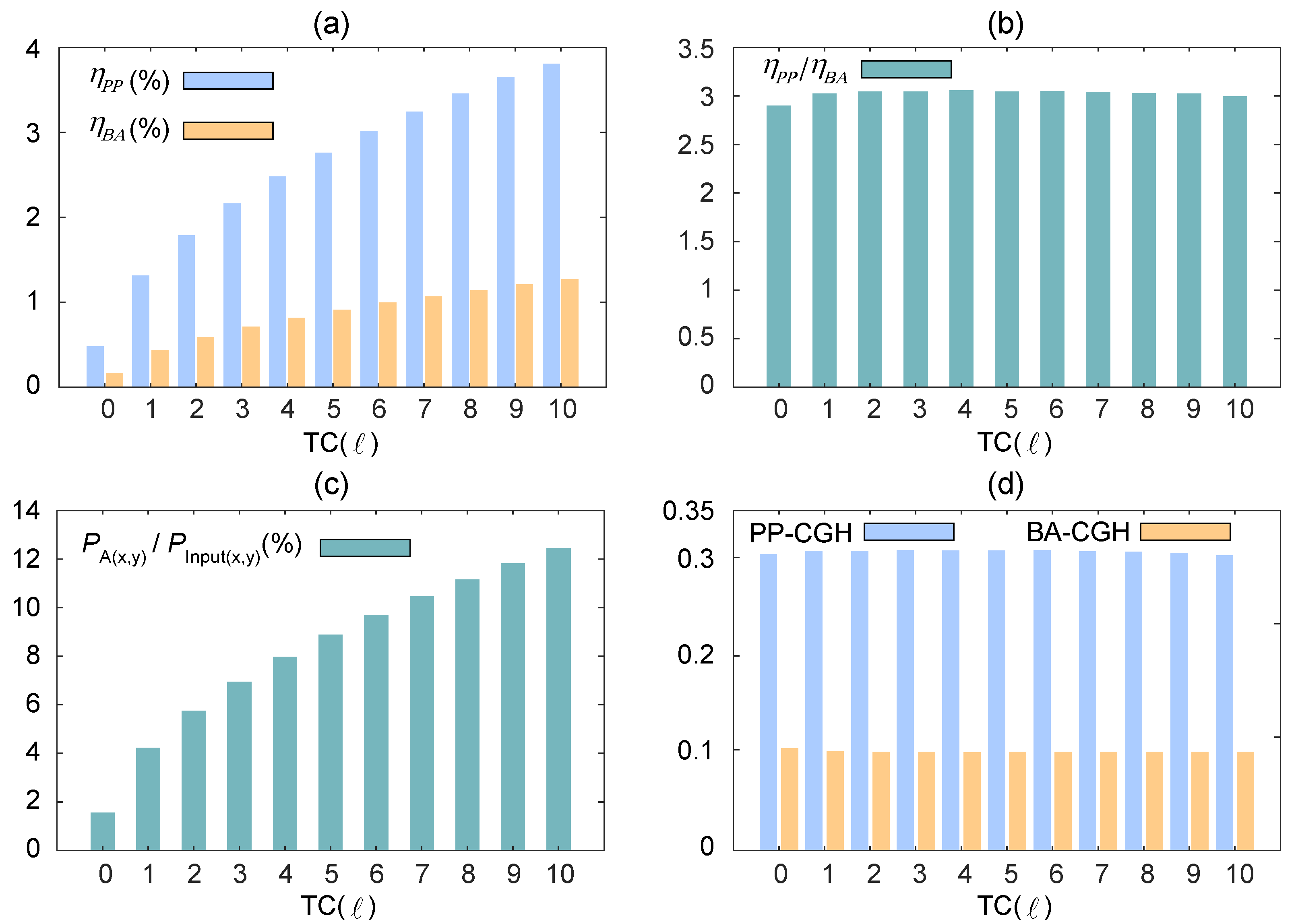
3.2. Efficiency of Holographic Tailoring
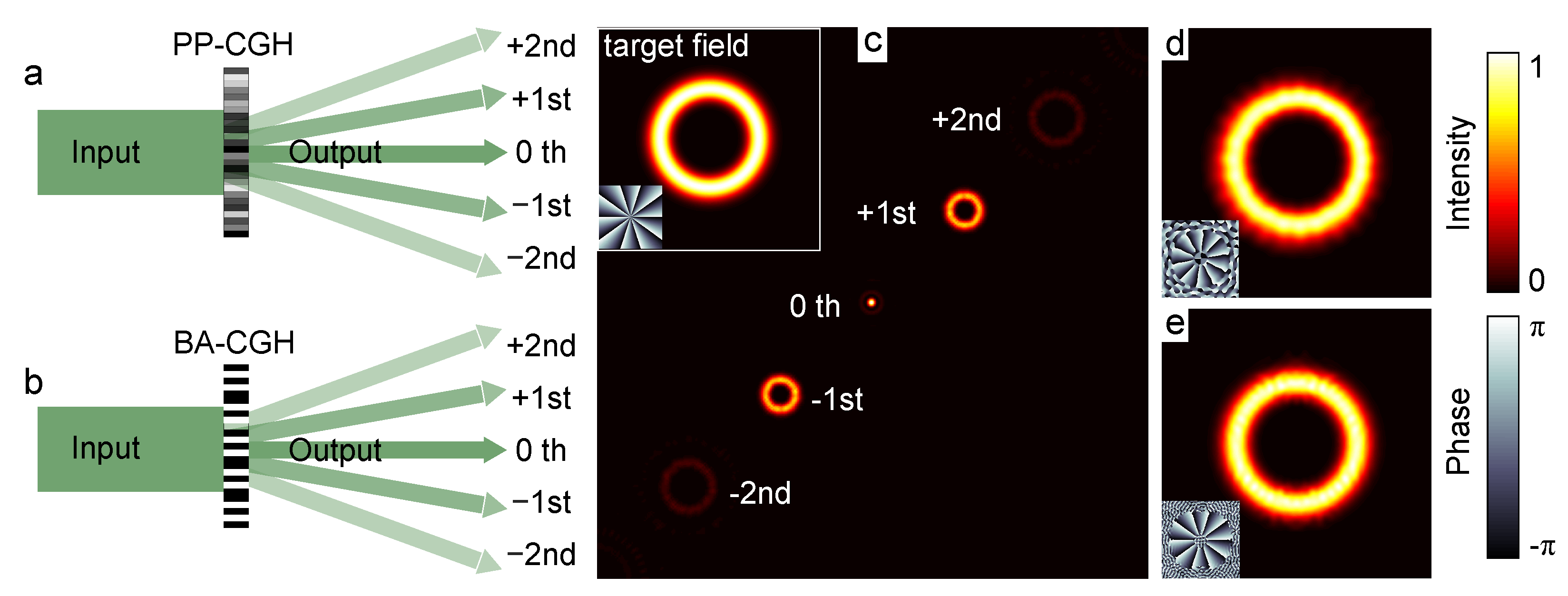
In this subsection, we focus on the modulation efficiency of two methods. As stated above, the digital holographic tailoring methods require the illumination of a planar light wave on the CGH hologram. The efficiency of holographic tailoring can be expressed as the energy of +1st order (target beam, in Figure 3c) P + 1 divided by the energy of the input planar wave within the computational aperture P in :
η m o d = P + 1 P in
where m o d denotes P P and B A for PP-CGH and BA-CGH methods, respectively.
We calculated the holographic tailoring efficiency for vortex light ( T C = 0 to 10) at a spatial resolution of 400 × 400 , where the beam spot radius covers 628 azimuthal pixels on the spatial light modulator. In this condition, the complex amplitude correlation degrees for all tailored vortex optical fields exceed 95 % . The tailoring efficiencies of PP-CGH and BA-CGH in Figure 6a,b demonstrate that the efficiency increases with TC for both PP-CGH and BA-CGH methods; and PP-CGH has a tailoring efficiency that is three times as large as that of BA-CGH for all cases with different TCs.
Furthermore, we show that the energy of target field P A ( x , y ) , where A ( x , y ) are amplitude-normalized L G 0 modes, reduces rapidly as the TC reduces, as illustrated in Figure 6c, where the ratio is the energy of the target field divided by the energy of the input planar wave (consistent) within the computational aperture. In addition, it is interesting that the extraction efficiency ( P + 1 / P A ( x , y ) ) is consistent against varying TC, as shown in Figure 6d, which suggests that the tailoring efficiency depends mainly on the intensity distribution of the target light field itself when using the holographic modulated tailoring of PP-CGH and BA-CGH. It is shown that approximately 30 % and 10 % of energy within the covering area of the target beam on the modulator can be converted to the target light field at the far field, using PP-CGH and BA-CGH methods, respectively.
The discrepancy between the two methods in term of the tailoring efficiency can be well explained by reviewing the structured light tailoring principles. Figure 7a,e illustrate the intensity and phase distribution of the target beam ( = 10 ). Figure 7b–d are the modulated normalized light field distribution of input light, zero order and +1st order in the PP-CGH method, respectively. Figure 7c shows that 68% of the energy of the input light is directly tailored in the covering region of the target beam on the modulator. Then, 45 % of the tailored energy is distributed to +1st order (the target beam), whereas the other 45 % is located at the −1st order and the other 10 % is located at the higher order. In total, the reconstructed beam obtains 100 % × 68 % × 45 % 30 % of the energy of the target area (as shown in Figure 7d). In contrast, Figure 7f–g are the normalized distribution of modulated light, zero order and +1st order in the BA-CGH method, respectively. Only half the energy of the input light within the target area is modulated due to 0/1 grating, as shown in Figure 7f. Then, approximately 50% of the modulated energy remains at zero order, whereas the other 45% is equally divided into the +1st order (target beam) and −1st order, and the other 10 % is located at the higher order, as indicated in Figure 7g. In total, the reconstructed beam obtains 100 % × 50 % × 50 % × 45 % 11 % of the energy of the target area, as shown in Figure 7d. In this regard, to achieve a higher tailoring efficiency, we need to cover the modulation area with the target light field as much as possible, or make the input light match the size of the target light field to distribute more energy into the target beam.

3.3. Discussion

The above analysis indicates that the two methods have a similar tailoring quality. However, in terms of the modulation efficiency, the efficiency of BA-CGH is only approximately one third that of PP-CGH. In addition, the devices for realizing PP-CGH and BA-CGH tailoring have their own characteristics in terms of cost, modulation speed, wavelength and polarization, as compared in Table 1. It is shown that structured light tailoring with an amplitude binary mask in DMD has a much faster modulation speed and moderately lower cost, which is beneficial to wider application scenarios. In addition, there are other parameters characterizing the digital devices, e.g., in the case of Lc-SLM: diffraction efficiency, number of gray levels/phase levels that can be addressed and fill factor; and, in the case of DMD: diffraction efficiency and fill factor, which can mildly influence the tailoring performance.

4. Conclusions

In summary, we have comprehensively demonstrated the structured light tailoring methods for PP-CGH and BA-CGH and the corresponding tailoring accuracy and efficiency. In theory, both methods can theoretically tailor arbitrary structured light perfectly. However, in practical applications, pixelated modulation devices introduce tailoring error and loss. We theoretically summarize the relationship between the tailoring accuracy and modulated pixel for the example of a vortex beam, and point out the optimization route and tailoring limit for the use of pixelated modulation devices. In addition, we demonstrate that PP-CGH has a tailoring efficiency three times that of BA-CGH. We conclude that one should always make the target beam cover as many pixels as possible on the modulator plane to obtain a higher tailoring accuracy and efficiency. This analysis will help researchers better use the digital holography method to achieve customized structured optical fields.

Author Contributions

Conceptualization, Z.W.; methodology, Z.W., Z.S.; software, Z.W.; validation, Z.W., X.F.; formal analysis, Z.W., X.F.; investigation, Z.W.; resources, Z.W.; data curation, Z.W.; writing—original draft preparation, Z.W.; writing—review and editing, Z.W., X.F.; visualization, Z.W.; supervision, Z.W., X.F., Q.L.; project administration, X.F.; funding acquisition, X.F., Q.L. All authors have read and agreed to the published version of the manuscript.

Funding

This work was funded by National Natural Science Foundation of China (61975087).

Data Availability Statement

Data underlying the simulation results presented in this paper are not publicly available at this time but may be obtained from the authors upon reasonable request.

Acknowledgments

We thank Zhaoyang Wang and Hao Wang for technical support and helpful discussions.

Conflicts of Interest

The authors declare no conflict of interest.

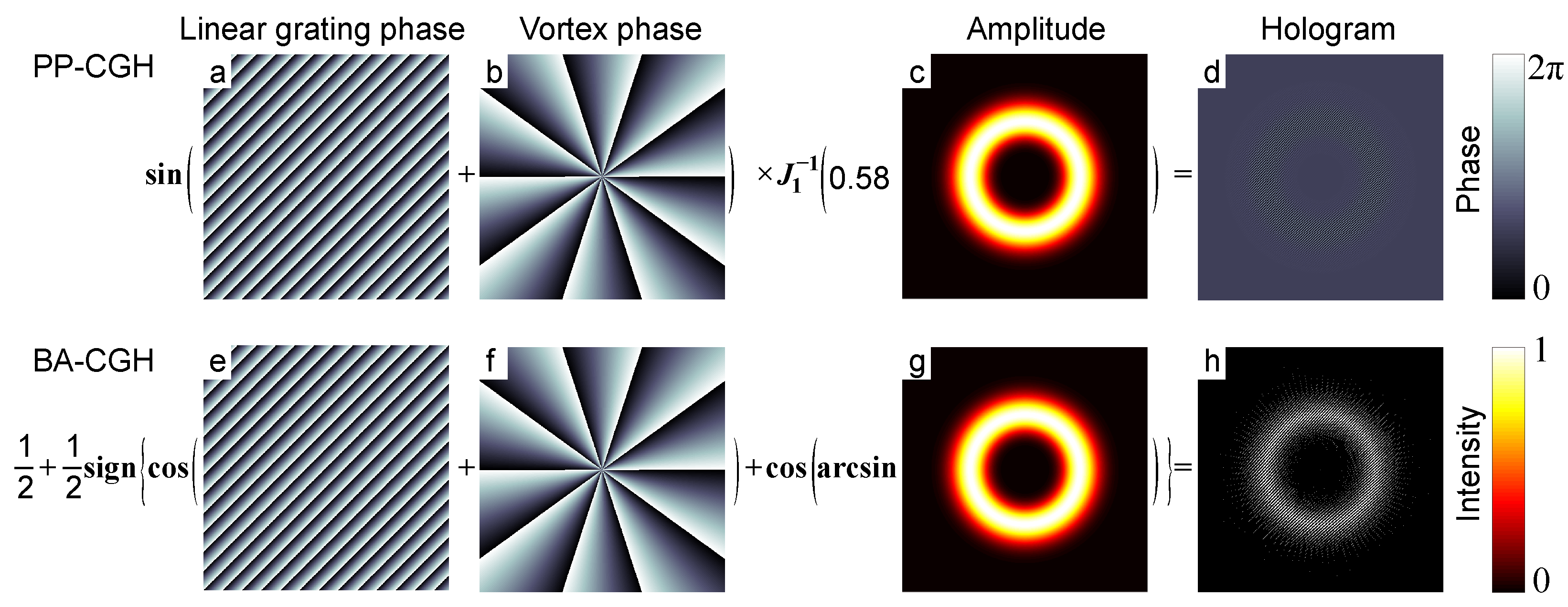
Appendix A. Generation of Pure Phase Holograms

Mathematically, a scalar structured light consists of spatially non-uniform amplitude and phase components, as expressed by:
E x , y = A x , y exp i Φ x , y
where A x , y 0 , 1 are the normalized amplitude function, Φ x , y π , π are the phase function. Thus, the complex amplitude values of the target optical field E x , y fall into a set of complex numbers with a modulus equal to or less than 1. The transmission function of a pure phase hologram depends entirely on the amplitude A x , y and phase functions Φ x , y , which are described as Ψ A x , y , Φ x , y . Then, the Fourier series expansion of a plane wave modulated by a phase hologram can be expressed as:
M x , y = exp i Ψ A x , y , Φ x , y = q = c q A exp i q Φ x , y c q A = 1 2 π π π M x , y exp i q Φ x , y d Φ
where c q A are coefficients of Fourier series, the phase function of the target field obtained in the +1st order Fourier series. Therefore, we can obtain the complete target field when the +1st order Fourier series coefficients satisfies c 1 A = C A (C is an arbitrary number). Substituting this condition into Equation (A2), we have:
C A = 1 2 π π π exp i Ψ A , Φ i Φ d Φ
Since the left side of the equation is a real function, the complex integral expansion of the right side has:
π π sin i Ψ A , Φ i Φ d Φ = 0 π π cos i Ψ A , Φ i Φ d Φ = 2 π C A
In this way, one know that the pure phase hologram Ψ A x , y , Φ x , y is oddly symmetric with variable Φ . Therefore, we can assume that the pure phase hologram is Ψ A , Φ = sin Φ × f A . Re-substituting this assumption into Equation (A2), we obtain
c q A = 1 2 π exp i Ψ sin Φ × f A i q Φ d Φ
The coefficients of the Fourier series can be derived as c A q = J q f A , where J q is the q t h Bessel function and the +1st order coefficients can be derived as c 1 A = C A , leading to the maximum value of C satisfying A = J 1 f A / C is approximately C = 0.582 . Thus, the amplitude function can be expressed as f A = J 1 C A , and the phase hologram is obtained as
Ψ A x , y , Φ x , y = sin Φ J 1 1 C A
Here, we have obtained the target field at +1st order Fourier series. However, all diffraction orders are spatially overlapping. A simple way to separate the target beam from the other orders is to add different spatial frequencies into different orders, which is shown as follows:
M S L M x , y = exp i Ψ A , Φ + 2 π u 0 x + v 0 y = q = c q A exp i q Φ x , y exp i q u 0 x + v 0 y = exp i sin Φ + 2 π u 0 x + v 0 y J 1 1 C A
It can be seen in the above equation that, when a linear grating is superimposed on the phase function, each of the Fourier terms in the expansion corresponds to a linear grating with an integer multiple of the relative initial linear grating period, respectively, meaning that each Fourier term corresponds to a separate transmission direction. Therefore, we can extract the +1st order that contains the components of the target beam.

Appendix B. Generation of Binary Amplitude Holograms

In contrast to the pure phase hologram of Lc-SLM, the binary amplitude hologram construction of DMD is directly related to the classical holographic method. We start from the holographic technique, which is centered on the interference pattern between the reference light wave (tilted plane wave, R x , y = R exp i 2 π x / T ) and the object light wave (target light field, E x , y = A x , y exp i Φ x , y ). The method of reconstructing the target light field is to illuminate the interference hologram by a reference beam, so that the diffracted beam contains components of the target optical field. The transmittance function of the interference hologram is
t x , y = R x , y + E x , y 2 = exp i 2 π x i 2 π x T T + A x , y exp i Φ x , y 2 = R 2 + E 2 x , y + 2 R A x , y cos 2 π x 2 π x T T + Φ x , y
The third term in Equation (A8) contains all of the information of the reference light and target light, which can be used for the target field reconstruction. The amplitude function 2 R A x , y cos 2 π x / T + Φ x , y is binarized by a zero threshold that the negative and positive values are reset as 0 and 1, respectively. The binary amplitude hologram is given by
T 1 x , y = 1 , cos 2 π x x T T + Φ x , y 0 0 , cos 2 π x x T T + Φ x , y < 0
where the information of the amplitude of the target beam in the amplitude function is lost. In principle, the phase and amplitude of the light can be modulated simultaneously by adjusting the local parameters of the binary amplitude hologram. While keeping the spatial periodicity of the binary amplitude hologram constant, the target amplitude is introduced as the bias term of the binary amplitude hologram to obtain the target amplitude and phase results in the diffracted beam. We set the target amplitude dependent function f A x , y = cos π q x , y as the bias function in Equation (A9), which can be rewritten as
T 2 x , y = 1 , cos 2 π x x T T + Φ x , y cos π q x , y 0 0 , cos 2 π x x T T + Φ x , y cos π q x , y < 0
The Fourier series of the binary amplitude hologram in Equation (A10) is expressed as
T 2 x , y = m = sin π m q x , y π m exp j m 2 π x x T + Φ x , y T + Φ x , y
where the phase part of the +1st order Fourier series is exactly the same as the target function, and the corresponding +1st order coefficient is sin π q x , y / π m . If sin π q x , y / π = C A x , y , which is a constant condition. At this point, it is possible to obtain the target complex amplitude light field at the +1st order Fourier series, and the corresponding bias function can be written as cos π q x , y cos arcsin A x , y for C = 1 / π . Thus, Equation (A9) can be rewritten as
T 2 x , y = 1 , cos 2 π x x T T + Φ x , y cos arcsin A x , y 0 0 , cos 2 π x x T T + Φ x , y cos arcsin A x , y < 0
In this method, the phase and amplitude of the target optical field are recorded by the position and width of the stripe along the tilted reference optical wave direction. The hard threshold in Equation (A12) is expressed as a symbolic function of
1 2 + 1 2 sign x = 1 , x 0 0 , x < 0
Thus, the transmission function of the binary hologram of the DMD can be further expressed as
T D M D x , y = 1 2 + 1 2 sign cos Φ + 2 π u 0 x + v 0 y + cos arcsin A x , y
where u 0 x + v 0 y represents any direction of the tilted reference optical wave. The binary amplitude modulation of DMD in Equation (A14) is similar to the pure phase modulation of SLM in Equation (A7), where the target optical field can be obtained by the +1st order diffraction of the Fourier series of the binary amplitude hologram.

References

  1. Forbes, A.; de Oliveira, M.; Dennis, M.R. Structured light. Nat. Photonics 2021, 15, 253–262. [Google Scholar] [CrossRef]
  2. Rubinsztein-Dunlop, H.; Forbes, A.; Berry, M.V.; Dennis, M.R.; Andrews, D.L.; Mansuripur, M.; Denz, C.; Alpmann, C.; Banzer, P.; Bauer, T.; et al. Roadmap on structured light. J. Opt. 2016, 19, 013001. [Google Scholar] [CrossRef]
  3. Wan, Z.; Shen, Y.; Wang, Z.; Shi, Z.; Liu, Q.; Fu, X. Divergence-degenerate spatial multiplexing towards future ultrahigh capacity, low error-rate optical communications. Light Sci. Appl. 2022, 11, 144. [Google Scholar] [CrossRef] [PubMed]
  4. Allen, L.; Beijersbergen, M.W.; Spreeuw, R.; Woerdman, J. Orbital angular momentum of light and the transformation of Laguerre-Gaussian laser modes. Phys. Rev. A 1992, 45, 8185. [Google Scholar] [CrossRef] [PubMed]
  5. Shen, Y.; Wang, X.; Xie, Z.; Min, C.; Fu, X.; Liu, Q.; Gong, M.; Yuan, X. Optical vortices 30 years on: OAM manipulation from topological charge to multiple singularities. Light Sci. Appl. 2019, 8, 90. [Google Scholar] [CrossRef] [Green Version]
  6. Yao, A.M.; Padgett, M.J. Orbital angular momentum: Origins, behavior and applications. Adv. Opt. Photonics 2011, 3, 161–204. [Google Scholar] [CrossRef] [Green Version]
  7. Shen, Y.; Meng, Y.; Fu, X.; Gong, M. Hybrid topological evolution of multi-singularity vortex beams: Generalized nature for helical-Ince–Gaussian and Hermite–Laguerre–Gaussian modes. J. Opt. Soc. Am. A 2019, 36, 578–587. [Google Scholar] [CrossRef]
  8. Chen, R.; Zhou, H.; Moretti, M.; Wang, X.; Li, J. Orbital angular momentum waves: Generation, detection, and emerging applications. IEEE Commun. Surv. Tutor. 2019, 22, 840–868. [Google Scholar] [CrossRef] [Green Version]
  9. Ettorre, M.; Pavone, S.C.; Casaletti, M.; Albani, M.; Mazzinghi, A.; Freni, A. Near-field focusing by non-diffracting Bessel beams. In Aperture Antennas for Millimeter and Sub-Millimeter Wave Applications; Springer: Cham, Switzerland, 2018; pp. 243–288. [Google Scholar]
  10. Zhan, Q. Cylindrical vector beams: From mathematical concepts to applications. Adv. Opt. Photonics 2009, 1, 1–57. [Google Scholar] [CrossRef]
  11. Willner, A.E.; Pang, K.; Song, H.; Zou, K.; Zhou, H. Orbital angular momentum of light for communications. Appl. Phys. Rev. 2021, 8, 041312. [Google Scholar] [CrossRef]
  12. Yang, Y.; Ren, Y.; Chen, M.; Arita, Y.; Rosales-Guzmán, C. Optical trapping with structured light: A review. Adv. Photonics 2021, 3, 034001. [Google Scholar] [CrossRef]
  13. Liu, K.; Cheng, Y.; Gao, Y.; Li, X.; Qin, Y.; Wang, H. Super-resolution radar imaging based on experimental OAM beams. Appl. Phys. Lett. 2017, 110, 164102. [Google Scholar] [CrossRef]
  14. Neo, R.; Leon-Saval, S.; Bland-Hawthorn, J.; Molina-Terriza, G. OAM interferometry: The detection of the rotational Doppler shift. Opt. Express 2017, 25, 21159–21170. [Google Scholar] [CrossRef]
  15. Arrizón, V.; Méndez, G.; Sánchez-de La-Llave, D. Accurate encoding of arbitrary complex fields with amplitude-only liquid crystal spatial light modulators. Opt. Express 2005, 13, 7913–7927. [Google Scholar] [CrossRef]
  16. Kirk, J.P.; Jones, A.L. Phase-only complex-valued spatial filter. J. Opt. Soc. Am. 1971, 61, 1023–1028. [Google Scholar] [CrossRef]
  17. Lee, W.H. Binary computer-generated holograms. Appl. Opt. 1979, 18, 3661–3669. [Google Scholar] [CrossRef]
  18. Davis, J.A.; Cottrell, D.M.; Campos, J.; Yzuel, M.J.; Moreno, I. Encoding amplitude information onto phase-only filters. Appl. Opt. 1999, 38, 5004–5013. [Google Scholar] [CrossRef] [PubMed]
  19. Huang, D.; Timmers, H.; Roberts, A.; Shivaram, N.; Sandhu, A.S. A low-cost spatial light modulator for use in undergraduate and graduate optics labs. Am. J. Phys. 2012, 80, 211–215. [Google Scholar] [CrossRef]
  20. Sampsell, J.B. Digital micromirror device and its application to projection displays. J. Vac. Sci. Technol. B Microelectron. Nanometer Struct. Process. Meas. Phenom. 1994, 12, 3242–3246. [Google Scholar] [CrossRef]
  21. Ren, Y.X.; Lu, R.D.; Gong, L. Tailoring light with a digital micromirror device. Ann. Phys. 2015, 527, 447–470. [Google Scholar] [CrossRef] [Green Version]
  22. Arrizón, V.; Ruiz, U.; Carrada, R.; González, L.A. Pixelated phase computer holograms for the accurate encoding of scalar complex fields. J. Opt. Soc. Am. A 2007, 24, 3500–3507. [Google Scholar] [CrossRef] [PubMed]
  23. Davis, J.A.; Valadéz, K.O.; Cottrell, D.M. Encoding amplitude and phase information onto a binary phase-only spatial light modulator. Appl. Opt. 2003, 42, 2003–2008. [Google Scholar] [CrossRef] [PubMed]
  24. Forbes, A.; Dudley, A.; McLaren, M. Creation and detection of optical modes with spatial light modulators. Adv. Opt. Photonics 2016, 8, 200–227. [Google Scholar] [CrossRef]
  25. Qu, G.; Yang, W.; Song, Q.; Liu, Y.; Qiu, C.W.; Han, J.; Tsai, D.P.; Xiao, S. Reprogrammable meta-hologram for optical encryption. Nat. Commun. 2020, 11, 5484. [Google Scholar] [CrossRef] [PubMed]
  26. Yepes, I.S.; Vieira, T.A.; Suarez, R.A.; Fernandez, S.R.; Gesualdi, M.R. Phase and intensity analysis of non-diffracting beams via digital holography. Opt. Commun. 2019, 437, 121–127. [Google Scholar] [CrossRef]
  27. Hu, X.; Rosales-Guzmán, C. Generation and characterization of complex vector modes with digital micromirror devices: A tutorial. J. Opt. 2021, 24, 034001. [Google Scholar] [CrossRef]
  28. Wan, Z.; Wang, Z.; Yang, X.; Shen, Y.; Fu, X. Digitally tailoring arbitrary structured light of generalized ray-wave duality. Opt. Express 2020, 28, 31043–31056. [Google Scholar] [CrossRef]
  29. Wan, Z.; Shen, Y.; Gong, M.; Fu, X. Quadrant-separable multi-singularity vortices manipulation by coherent superposed mode with spatial-energy mismatch. Opt. Express 2018, 26, 34940–34955. [Google Scholar] [CrossRef]
  30. He, T.; Meng, Y.; Liu, Z.; Hu, F.; Wang, R.; Li, D.; Yan, P.; Liu, Q.; Gong, M.; Xiao, Q. Guided mode meta-optics: Metasurface-dressed waveguides for arbitrary mode couplers and on-chip OAM emitters with a configurable topological charge. Opt. Express 2021, 29, 39406–39418. [Google Scholar] [CrossRef]
  31. da Silva, B.P.; Marques, B.; Rodrigues, R.; Ribeiro, P.S.; Khoury, A. Machine-learning recognition of light orbital-angular-momentum superpositions. Phys. Rev. A 2021, 103, 063704. [Google Scholar] [CrossRef]
Figure 1. Intensity (top) and phase (bottom) pattern of LG mode with different TC ( ) .
Photonics 09 00506 g001
Figure 2. An example of constructing CGH hologram, (ad) are construction method for PP-CGH (where J 1 1 is inverse of 1 s t Bessel function), (eh) are construction method for BA-CGH and (d,h) are phase gray hologram and binary amplitude hologram of LG 0 10 , respectively.
Photonics 09 00506 g002
Figure 3. Schematic diagram of PP-CGH and BA-CGH for generating structured light. (a,b) show that the input beam is modulated and diffracted into multiple orders for the binary amplitude hologram and phase gray hologram, respectively. (c) shows the partially separated orders on the far-field pattern of binary amplitude or phase gray diffracted hologram of LG 0 10 mode by illuminating a plane wavefront, while the intensity and phase of target beam are inserted in the upper left corner. (d,e) shows the reconstructed intensity and phase by extracting the +1st diffraction order for PP-CGH and BA-CGH, respectively.
Photonics 09 00506 g003
Figure 4. Schematic of reconstructed vortex beam under discretized azimuthal phase. (a) The phase sampling in a finite resolution ( 40 × 40 ) phase diagram, (b) the discretized azimuthal phase with different pixels, (c) intensity of the vortex light field with different radii, where (d,e) are the intensity, phase and OAM spectrum of the reconstructed field. (b1e1, b2e2 and b3e3 correspond to the optical field radius proportion of 25 % , 50 % and 80 % , respectively, relative to the computational aperture).
Photonics 09 00506 g004
Figure 5. The complex amplitude correlation degree of vortex beam versus different TCs and different available pixel numbers for PP-CGH (a) and BA-CGH (b).
Photonics 09 00506 g005
Figure 6. Tailored efficiency of holographic generation for vortex beams. (a) Bar chart of tailoring efficiency for PP-CGH and BA-CGH methods, (b) ratio of tailoring efficiencies of two methods, (c) the ratio of target light field energy to energy within the computational aperture and (d) extraction efficiency of target light field for PP-CGH and BA-CGH methods.
Photonics 09 00506 g006
Figure 7. Schematic of tailoring of vortex beams ( = 10 ) with PP-CGH and BA-CGH methods, (a) energy of target is 100 % , (bd) and (eg) are the modulated normalized light field distribution of input light, 0th order, and +1st order in the PP-CGH and BA-CGH method, respectively, while extraction efficiencies (inserted in upper right coner) of PP-CGH method and BA-CGH method are 30% and 11 % , respectively.
Photonics 09 00506 g007
Table 1. Comparison of Lc - SLM and DMD for structured light tailor.
Modulator Lc - SLM DMD
TraitsLow refresh rate (50–500 Hz); polarization-sensitive; wavelength-sensitive; temperature-sensitive; relatively high efficiency(≤20%); expensiveHigh refresh rate (10 kHz–30 kHz); polarization-insensitive; wavelength-insensitive; temperature-insensitive; low efficiency(≤5%); relatively cheap
Publisher’s Note: MDPI stays neutral with regard to jurisdictional claims in published maps and institutional affiliations.

