1. Introduction
The Soleil–Babinet compensator (SBC) is a variable retarder, which can be used to generate continuous phase retardation to the incident linearly polarized light by adjusting its vernier micrometer [
1,
2]. Therefore, the SBC has been applied to produce phase retardation in a variety of fields, such as spectroscopic ellipsometer [
3,
4], Raman spectra analysis [
5], optical interferometry with weak measurement [
6], phase retarder aligned [
7,
8], quantum physics [
9], quantum communication [
10], and ultrafast pulse waveform measurement [
11]. However, the SBC needs to be calibrated for performing phase modulation with high precision [
12,
13]. Numerous methods and schemes have been proposed for the calibration of the SBC. With the advantages of simple and easy operation, the intensity method has been adopted in the early scheme. In this method, the SBC is placed between two orthogonal polarizers with its optical axis oriented at 45° with respect to that of the polarizer [
14]. By observing the two extinction states, the phase retardations for 0 and 2
π can be quickly located. However, whether the phase retardation of the SBC is linearly correlated with the displacement of the micrometer screw or not is difficult to verify because of the inevitable disturbed factors. In order to overcome the drawback of the intensity method, Wang et al. proposed a method to calibrate the SBC [
15]. The method uses a spectrophotometer and is realized by recording the relationship between the transmittance and the wavelengths. However, this method cannot be used to measure the zero-order retardation directly, so a multiple-order half-wave plate is additionally needed and its phase retardation must be measured beforehand. Further, Zhang et al. demonstrated the heterodyne interferometry scheme for calibrating the SBC, in which the beat frequency is generated by two acousto-optic modulators [
16]. In this scheme, the phase retardation is obtained by comparing the phase difference between the reference beam and measurement beam, so an arbitrary retardation between 0 and 2
π can be measured accurately and continuously. In addition, Bhattacharyya et al. presented the Mueller matrix polarimeter method to calibrate the retardation of the SBC [
17]. The retardation in this method is calculated by decomposing the Mueller matrix over the displacement. Because the retardation is determined by the arc cos function, it has been unwrapped with the intention to obtain the retardation that varies from −
π to
π.
It is worth noting that the pervious methods for the calibration of the SBC all take advantage of the homogeneously polarized property of the light. However, the vector beams (VBs), which have spatially inhomogeneous states of polarization [
18], have not been employed to calibrate the SBC, to the best of our knowledge. In recent years, the VBs have attracted significant interest due to the space-variant polarization states and annular intensity distribution in the transverse plane [
19] and have been exploited in many scientific and engineering applications, such as laser material processing [
20], optical trapping and manipulation [
21], quantum information processing [
22,
23], optical communication and super-resolution microscopy [
24,
25]. Typically, the polarization states of the VBs can be described by the high-order Poincaré sphere (HOPS) [
26], and the VBs can be generated by the superposition of two vortex beams with opposite topological charges and opposite uniform circular polarizations [
27]. The spatial light modulator (SLM) and the spiral phase plate (SPP) are widely used to generate the vortex beams [
28]. Compared with the SLM, as a solid-state optical device, though the SPP has poor flexibility to generate arbitrary vortex beams, it can bear high incident laser power, and make the experimental system more compact and stable [
29].
In this paper, we propose a scheme to calibrate the SBC based on the vectorial optical field. In this scheme, the experimental configuration is mainly composed of a SPP and a modified Mach–Zehnder interferometer with a dove prism, and the vector beam on the HOPS is generated on the grounds of the superposition principle with the left-handed and right-handed circularly polarized vortex beams. The polarization modulation characteristic of the SBC to the VBs is analyzed, and the relationship between the rotation angle of the petal-like intensity pattern and the phase retardation of the SBC is established. By calculating the rotation angles of the petals, the phase retardation characteristic of the SBC is measured with high accuracy.
2. Experimental Setup and Principle
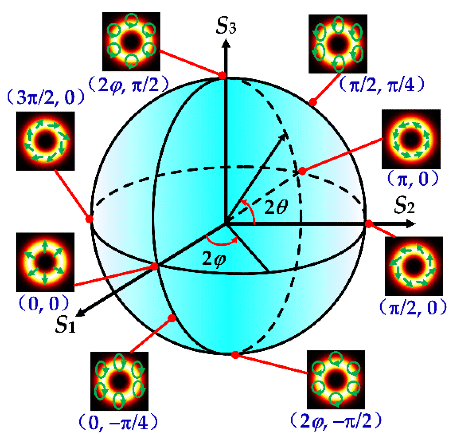
The polarization characteristic of the vector beam can be described by means of a high-order Poincaré sphere (HOPS) [
26].
Figure 1 shows a typical schematic illustration of the HOPS with the topological charge
l = 1, in which 2
θ∈(−
π/2,
π/2) and 2
φ∈(0, 2
π) represent the polar angle and the equator angle of arbitrary points on the surface, respectively. As shown in
Figure 1, on the equator, the points (2
φ, 0) represent the cylindrical vector beams. Particularly, the points (0, 0) and (
π, 0) correspond to the radially and azimuthally polarized beams, respectively [
30]. The points that locate on the north (2
φ,
π/2) and south (2
φ, −
π/2) poles denote the left-handed and right-handed circularly polarized vortex beams, respectively. Other points on the surface represent the elliptical vector beams. In general, the vector beam with a polarization state on the HOPS can be generated by the superposition of two orthogonal circularly polarized vortex beams with opposite topological charges.
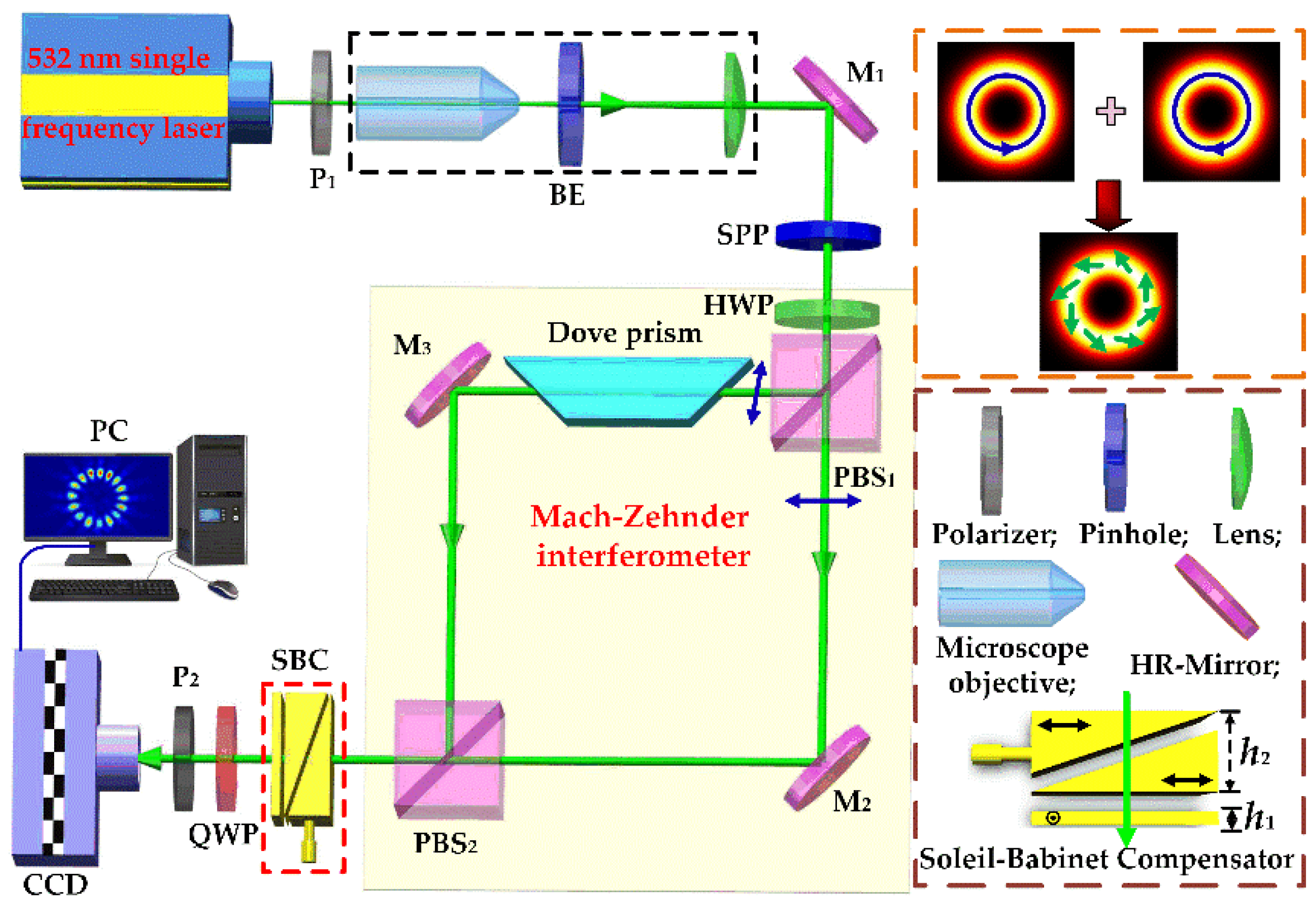
In our experiment, the setup for generating the vector beam on the HOPS and accomplishing the calibration of the SBC (GCO-030101, DHC Inc. Beijing, China) is shown in
Figure 2. The laser source is a solid-state single frequency laser (Model: CNILASER-MSL-DS-532) with a center wavelength of 532 nm and a maximum output power of 30 mW. A polarizer (P
1) with its axis oriented at the
x-axis is used to generate the horizontal polarized beam. Then, the linearly polarized beam is expanded and collimated to an expanded beam with a size of approximately 3 mm in diameter by the beam expander (BE), which is composed of a microscope objective, a spatial pinhole and a collimating lens. In order to add the spiral phase to the fundamental mode laser, a spiral phase plate (SPP) is chosen mainly considering the stability and reliability of the experimental system. After being phase modulated, the vortex beam is generated, with the Jones vector expressed as
. Here,
is the azimuthal angle, and
l is order of the topological charge.
A half-wave plate (HWP) with its fast axis oriented at an angle
β with respect to
x-axis is inserted behind the SPP to adjust the polarization of the vortex beam. After passing through the HWP, the Jones vector of the vortex beam is converted into
. Then, the linearly polarized vortex beam is split into horizontally and vertically polarized vortex beams via a polarizing beam splitter (PBS
1), in which the horizontal component propagates through the PBS
1, while the vertical component is fully reflected. A dove prism is added into the Mach–Zehnder interferometer to obtain opposite topological charges between the two orthogonally polarized vortex beams. After being reflected by the high reflection mirrors (M
2 and M
3), the two vortex beams are recombined and superposed coaxially by PBS
2, and the Jones vector of the combined vortex beam can be expressed as:
To generate the vector beam, a quarter-wave plate (QWP) is added behind the PBS
2 with its fast axis oriented at 45° to change the polarization states of the combined vortex beam. Therefore, the two components with orthogonal polarization among the combined vortex beam will be converted into left-handed and right-handed circularly polarized beams, respectively. After that, the vector beam is eventually synthesized, and its Jones vector can be given by:
From Equation (2), it can be found that the ellipticity angle of the generated vector beam is equal to (2
β −
π/4). It is noteworthy that the angle
θ∈(−
π/4,
π/4) on the HOPS also represents the ellipticity angle of the vector beam [
31]. Therefore, according to the consistent definition of the (2
β −
π/4) and
θ, the Jones vector of the generated vector beam also has the following form [
31]:
From the above analysis, it is observed that an arbitrary vector beam on the HOPS with the order
l can be generated by controlling the parameters
θ and
ϕ. To calibrate the SBC using the vectorial optical field, the SBC is inserted between the PBS
2 and the QWP. In the experiment, the SBC is composed of three single quartz elements: one fixed wedge, another translational wedge and one rectangular quartz crystal, as shown in
Figure 2. The optical axis of the rectangular crystal is perpendicular to that of the two wedges, while the axes of the two wedges are parallel to each other. The thickness (
h1) of the rectangular crystal is a constant, while the total thickness (
h2) of the two wedges can be continuously changed with the movement of the translational wedge through adjusting its micrometer screw. As a phase modulation device, the Jones matrix of the SBC can be expressed as [
3]:
where
is the phase retardation of the SBC [
32]. Here,
no and
ne denote the refractive indices of the quartz for the ordinary light and extraordinary light, respectively, and
λ is the wavelength of the incident light. After the recombined vortex beam passing through the SBC and QWP in turn, the final output optical field can be expressed as:
From Equation (5), it is clear that the phase retardation of the SBC will make the polarization state change along the equator of the HOPS. In order to analyze the mode of the generated vector beam, a polarizer (P
2) with its axis oriented at an angle
γ with respect to
x-axis is inserted between the QWP and the CCD camera, as shown in
Figure 2. The Jones matrix of the P
2 can be expressed as [
33]:
After the generated vector beam is transmitted through the P
2, combining Equations (5) and (6), the final intensity distribution that detected by the CCD, can be calculated as:
where
I0 =
A02 is the intensity. For simplicity, the amplitude distribution of the vortex beam, whose radial index is zero and azimuthal index is
l, can be simply expressed as [
34]:
where
E0 is the amplitude constant, and
ω0 is the waist width of the vortex beam.
From Equation (7), it is easy to find that the transmitted intensity distribution is modulated by a sine function. So the transmitted intensity will satisfy the petal-like distribution, and there are 2|l| pieces of intensity petals in the captured images by CCD. In addition, when the orientation of the polarizer (P2) or the phase retardation of the SBC is changed, the petal will rotate around the center. Meanwhile, the rotation angles of the petal are 1/|l| and 1/(2|l|) times compared with the change in orientation of the P2 and the change of the phase retardation of the SBC, respectively. Based on these analyses, the phase retardation characteristic of the SBC can be measured, and the feasibility of the proposed scheme can be verified by measuring the certain rotation angles of the polarizer.
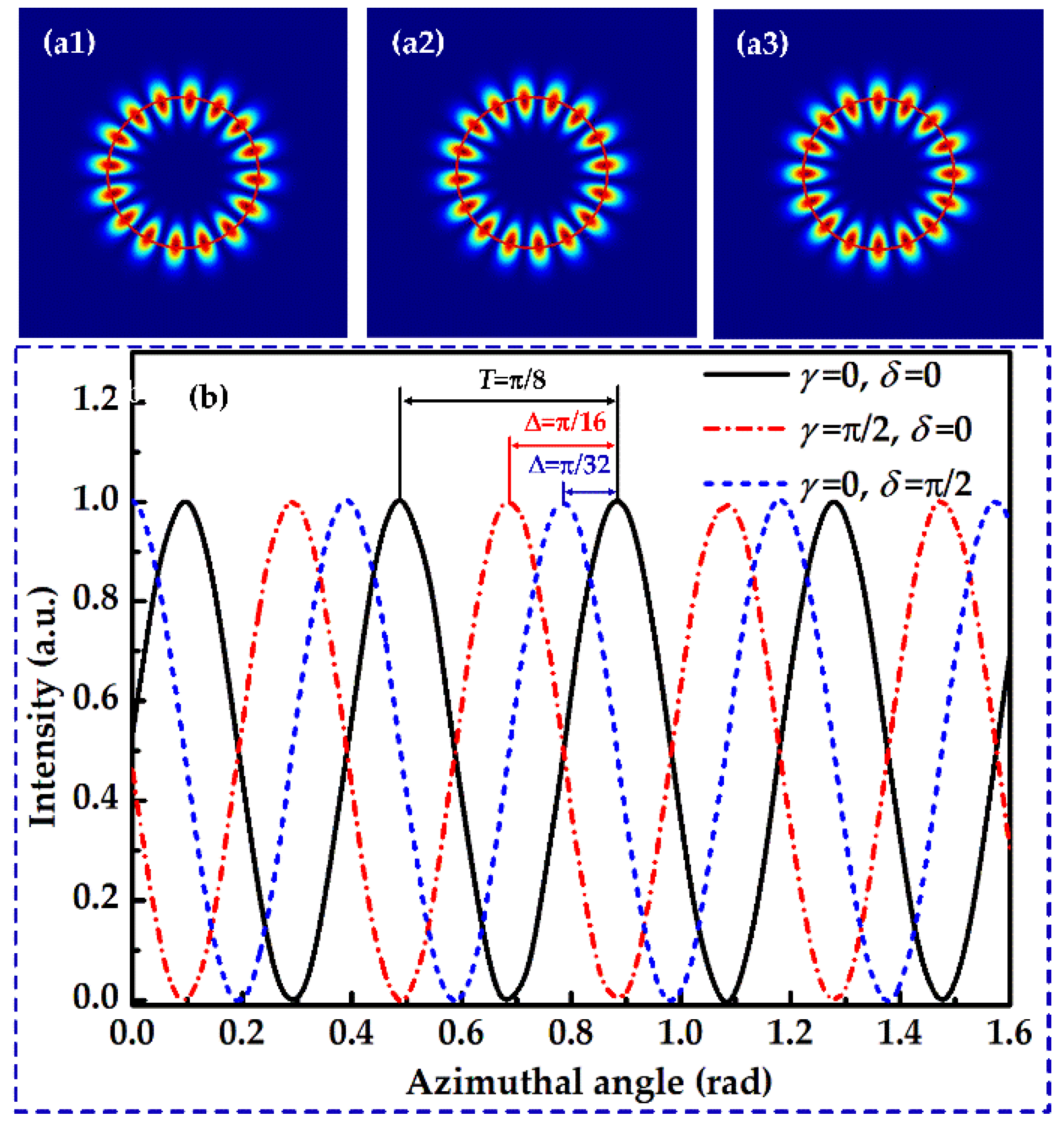
When the value of
θ is set as
θ = 0, the polarization of the vector beam is located on the equator of the HOPS according to Equation (5) and the cylindrical vector beam is generated. The simulated intensity distribution that the cylindrical vector beam with
l = 8 passes through a linear polarizer (P
2) are shown in
Figure 3. When there is no phase retardation, the simulated results for the polarizer placed along the
x-axis and
y-axis are depicted in
Figure 3(a1,a2), respectively. For the case that the phase retardation of SBC is
π/2 and the polarizer is placed along the
x-axis, the simulated result is presented in
Figure 3(a3). It can be seen that the number of petals is 16, and the petal patterns rotate with the rotation of the P
2 or the change of the phase retardation of the SBC. In
Figure 3(a1–a3), the red cycles are obtained by fitting the centroid of each petal in the petal-like intensity patterns. The intensity distributions on the red cycles of
Figure 3(a1–a3) are plotted as shown in
Figure 3b, in which the results that correspond to the quarter of a period are demonstrated for manifesting the results more clearly. From
Figure 3b, it can be seen that the angle between two adjacent petals in a petal pattern is
π/8. When the orientation of the polarizer changes at an angle of
π/2, the petals rotate at an angle of
π/16. The rotation angle of the petals is
π/32, when the phase retardation of the SBC is changed by
π/2. The results agree well with the theoretical analysis in Equation (7).
3. Experimental Results
It is well known that the measurement error can be minimized by multiple measurements [
35]. As shown in the theoretical analysis, the higher the order of the vector beam, the greater the number of petals obtained. In our scheme, the calibration of the SBC is performed by detecting the rotation angle of the petal patterns. Therefore, for the higher-order vector beam, there will be more information about the variation of the position of the intensity distribution, then the rotation angle can be determined with higher precision by averaging all the variations of the petal positions. In the experiment, considering the fabrication accuracy and the cost, a SPP with
l = 8 is used to transform the incident Gaussian beam into vortex beam. Consequently, there will be 16 pieces of petals, which is enough to determine the rotation angle of the petal-like pattern with high precision.
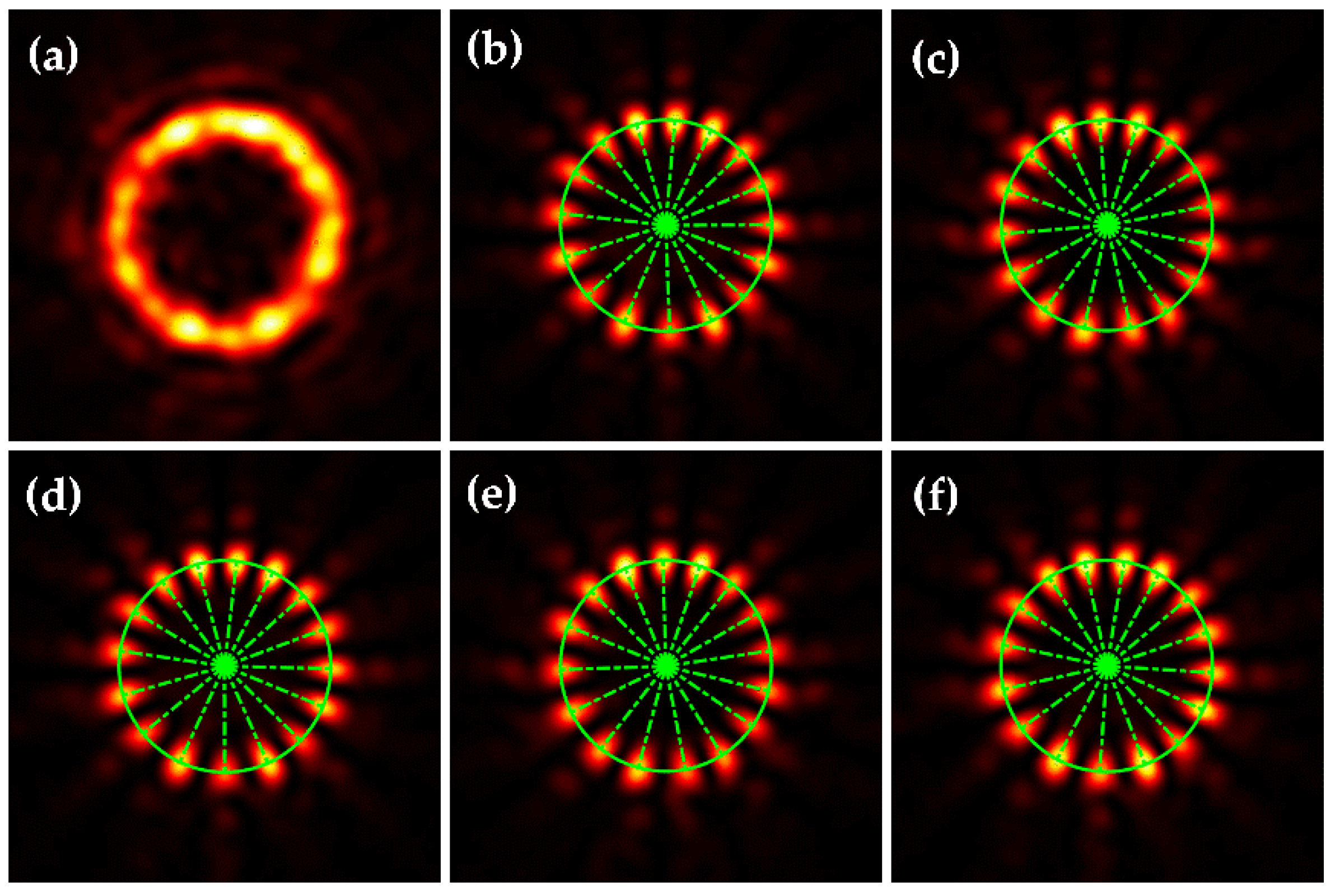
The experimentally generated vector beam is given in
Figure 4a. After passing through the polarizer (P
2), the petal-like intensity pattern of the vector beam is shown in
Figure 4b, and the number of petals is 16. Rotating the orientation angle of P
2 at 40° increments, the corresponding petal patterns are acquired and processed to verify the feasibility of the experimental scheme.
Figure 4b–f show the caught partial petal patterns after the P
2 with the orientation of 0°, 80°, 160°, 240° and 320°, respectively. In
Figure 4b–f, the green cycles are obtained by fitting the centroids of all the petals, and the green lines are the connection lines between the center of the petal pattern and the centroids of each petal.
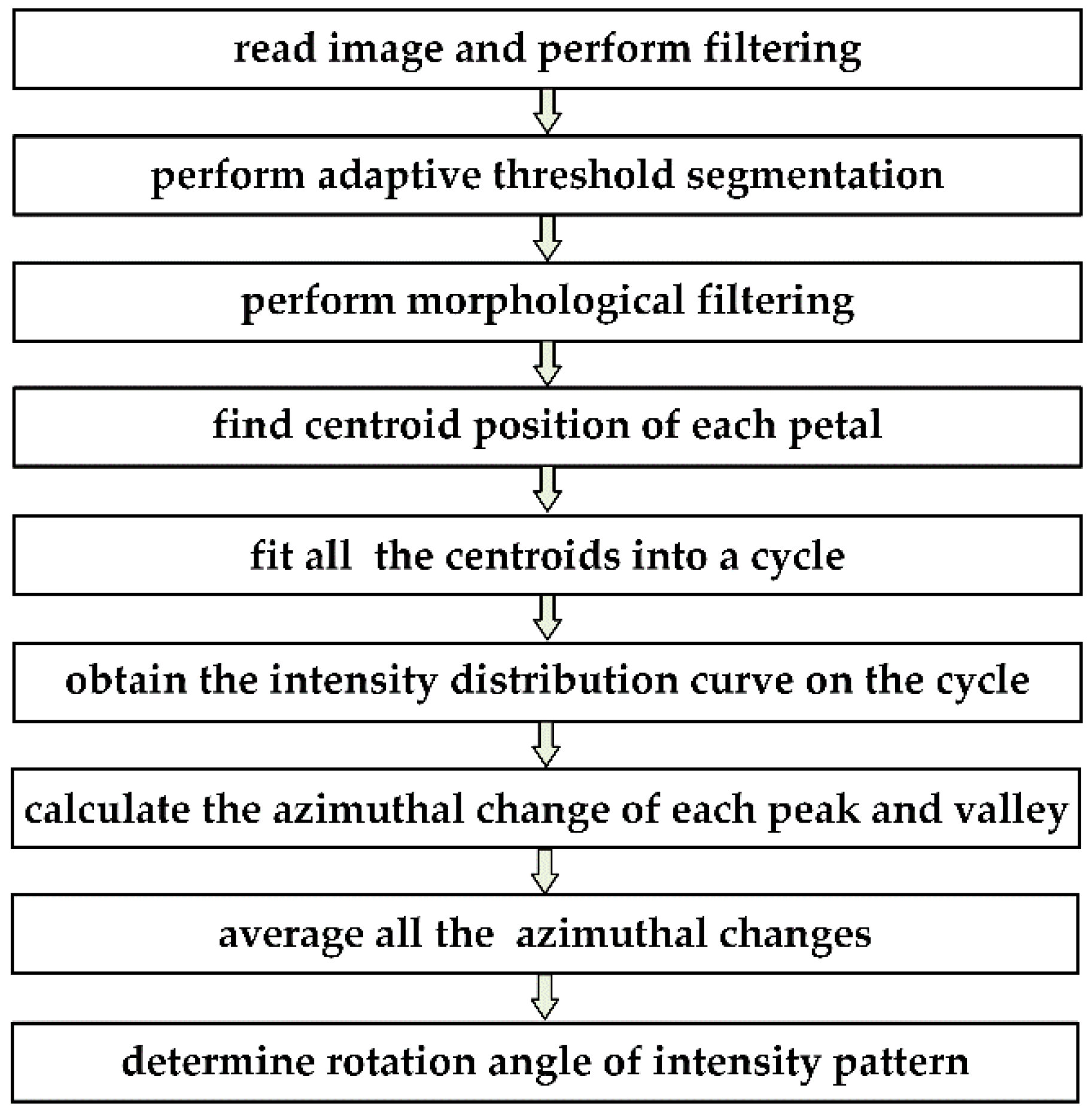
In order to obtain the rotation angle, the acquired images by the CCD are processed as the following procedure as shown in
Figure 5. First of all, the petal images are read and preprocessed by performing the digital filtering to reduce the noise. Secondly, considering the nonuniform intensity distribution of the vector beam, the preprocessed images are binarized based on adaptive threshold segmentation, and the morphological filtering technique is employed to remove the small areas resulting from the impure radial components of the vector beam as shown in
Figure 4. Thirdly, each petal is treated as the effective area to calculate its centroid location, and a cycle is obtained through fitting all of the centroids. Fourthly, the intensity curve on the fitted cycle of the petal pattern is plotted, and the peaks and valleys that distribute with the azimuthal angle are numbered, respectively. For the vector beam with the order 8, the number of peaks and valleys is 16. Then, the relative changes of the azimuthal angles of the peaks and valleys that correspond to the petal patterns before and after rotating are calculated. Finally, the rotation angle of the petal pattern is determined by averaging the entire relative changes of the azimuthal angles.
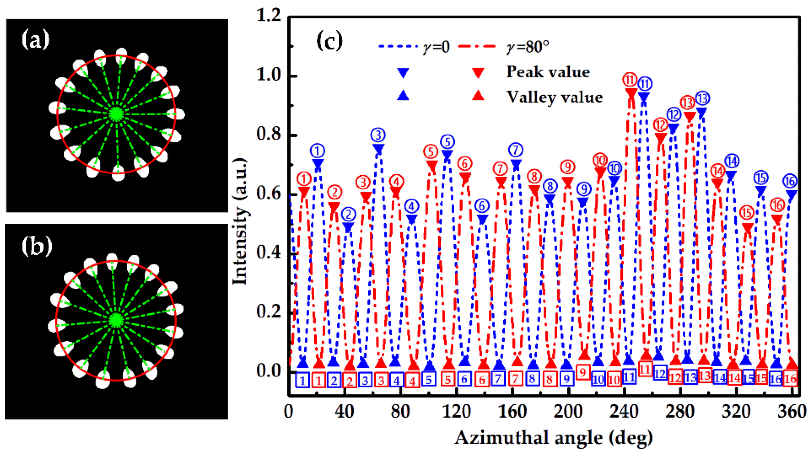
In order to demonstrate the image processing method more clearly, two images that are acquired in the experiment are processed and given as an illustration as shown in
Figure 6. Following the image processing method shown in
Figure 5, the processed images are given in
Figure 6a,b, which correspond to the results before and after the polarizer (P
2) rotating at an angle of 80°, respectively. The intensity distributions on the red cycles of
Figure 6a,b are plotted in
Figure 6c, in which the blue line and the red line represent the results before and after P
2 rotating. To calculate the rotation angle of the petal patterns, the peaks and the valleys of the intensity curves for the same petals before and after rotating are all marked using the same number to be identified. Through calculating the relative movement of the peaks with the same number and the relative movement of the valleys with the same number, the rotation angle of the pattern can be determined with improved precision by averaging the 32 sets of data.
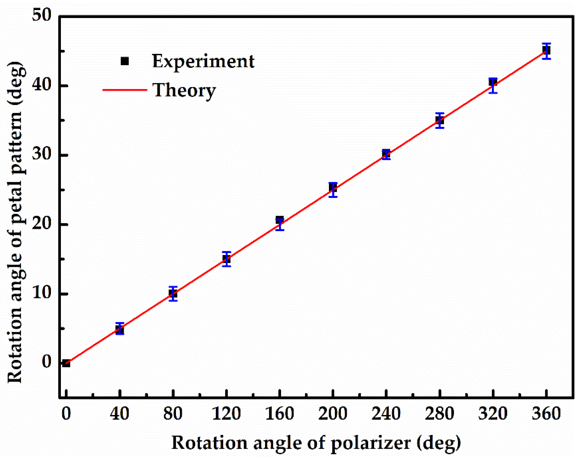
Figure 7 shows the processed results for the caught images by rotating the P
2 as given in
Figure 4. From
Figure 7, it can be seen that the slope is 0.1259 ± 0.0006 by linearly fitting the experimental data. According to the theoretical analysis in Equation (7), the petal patterns will rotate at an angle of
γ/|
l| when the polarizer rotates at an angle of
γ. Therefore, the experimental results agree well with the theoretical values, and the feasibility of the proposed scheme has been verified. So the phase retardation characteristic of the SBC can be measured with high accuracy by this scheme.
In the experiment, in order to calibrate the SBC, the optical axes of the SBC need to be consistent with the horizontal polarization direction, so the azimuth of the SBC is adjusted as the following steps. Firstly, an aperture is used to block the vortex beam with vertical polarization in the Mach–Zehnder interferometer, and the QWP (in
Figure 2) is removed temporarily. Then, the polarizer P
2 is rotated until the extinction phenomenon is observed. After the SBC is inserted into the experimental setup as shown in
Figure 2, the optical face of the SBC is carefully arranged to ensure the vortex beam with horizontal polarization is normal incident on the SBC. Thirdly, the SBC is adjusted around the light transmission direction until the extinction phenomenon is observed again, which indicates the azimuthal calibration of the SBC is accomplished. After that, rotate the SBC by 45° carefully, and adjust the micrometer screw continuously until that twice extinction phenomena are observed. The two displacements of the micrometer screw with the extinction phenomena are 8.40 and 19.33 mm, which correspond to zero and 2
π phase retardation, respectively. Finally, the SBC is rotated back 45°, and the QWP is inserted into the experimental setup. After the aperture is removed, the petal pattern is observed again. In order to obtain the phase retardation characteristic of the SBC, the phase retardation of the SBC is manually adjusted by the micrometer screw at 1 mm increments. By means of the image processing method as shown in
Figure 5, the acquired images that carry the phase retardation information of the SBC are processed to calculate the rotation angles of the patterns. According to the theoretical analysis in Equation (7), the ratio between the phase retardation and the rotation angle of the petal pattern is equal to 2|
l|. Thus, the relationship between the phase retardation of the SBC and the displacements of its micrometer screw is obtained.
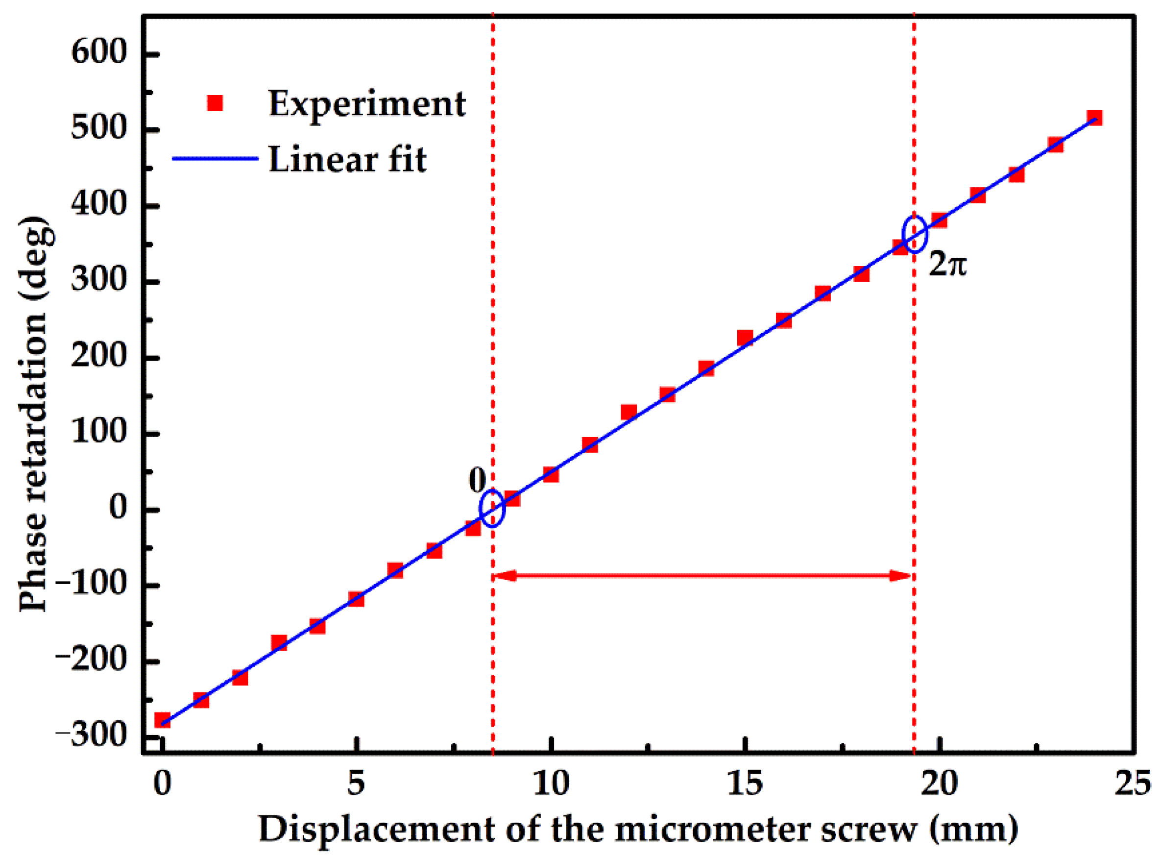
Figure 8 shows the experimentally measured phase retardation variation of the SBC as a function of the displacement of the micrometer screw, in which the red squares and the blue line represent the experimental results and the linearly fitted results, respectively. It can be seen that the measured phase retardation increases linearly from −277.00° to 516.57°, and the phase retardation region that ranges from zero to 2
π is marked by the red dotted lines. By linearly fitting the experimental data, the coefficient is 33.076 ± 0.147 °/mm. The coefficient of determination (R
2) value, which shows the linearity of the obtained data is 0.9995.
The phase retardation of the SBC at any other wavelength (
λ) can be calculated through the following equation [
36]:
where Δ
nλ = (
ne −
no) is the birefringence of the quartz, which can be given by [
37]:
where
T is the temperature, which is 25 °C in the experiment. In the operation instructions, the theoretical value of 27.289 °/mm for the wavelength of 632.8 nm has been given, then the theoretical value of 32.979 °/mm can be derived from Equations (9) and (10). Therefore, the measured results agree well with the theoretical value, and the phase retardation characteristic of the SBC is measured well with the aid of the proposed scheme.


