Half-Period Gray-Level Coding Strategy for Absolute Phase Retrieval


Abstract
:1. Introduction
2. Principles
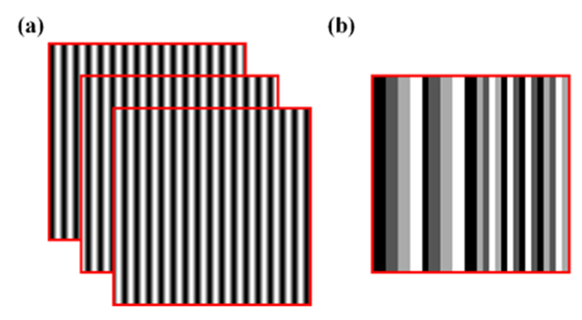
2.1. Three-Step Phase-Shifting Method
2.2. The Proposed Method
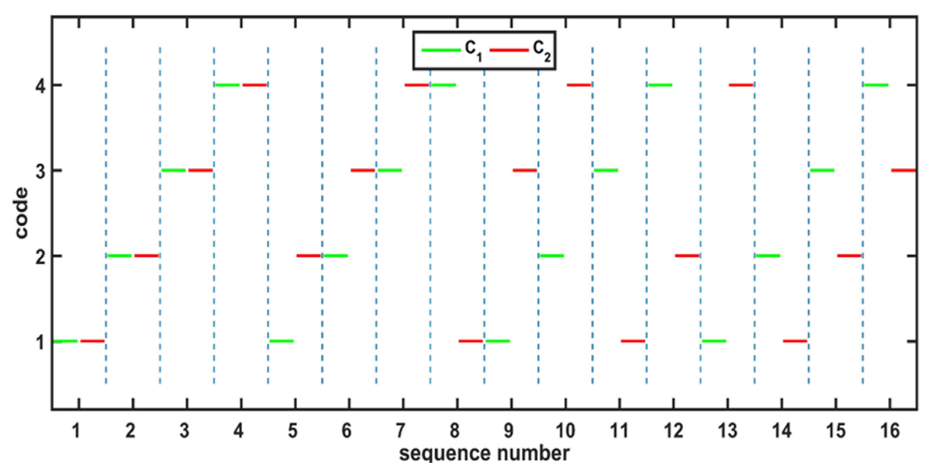
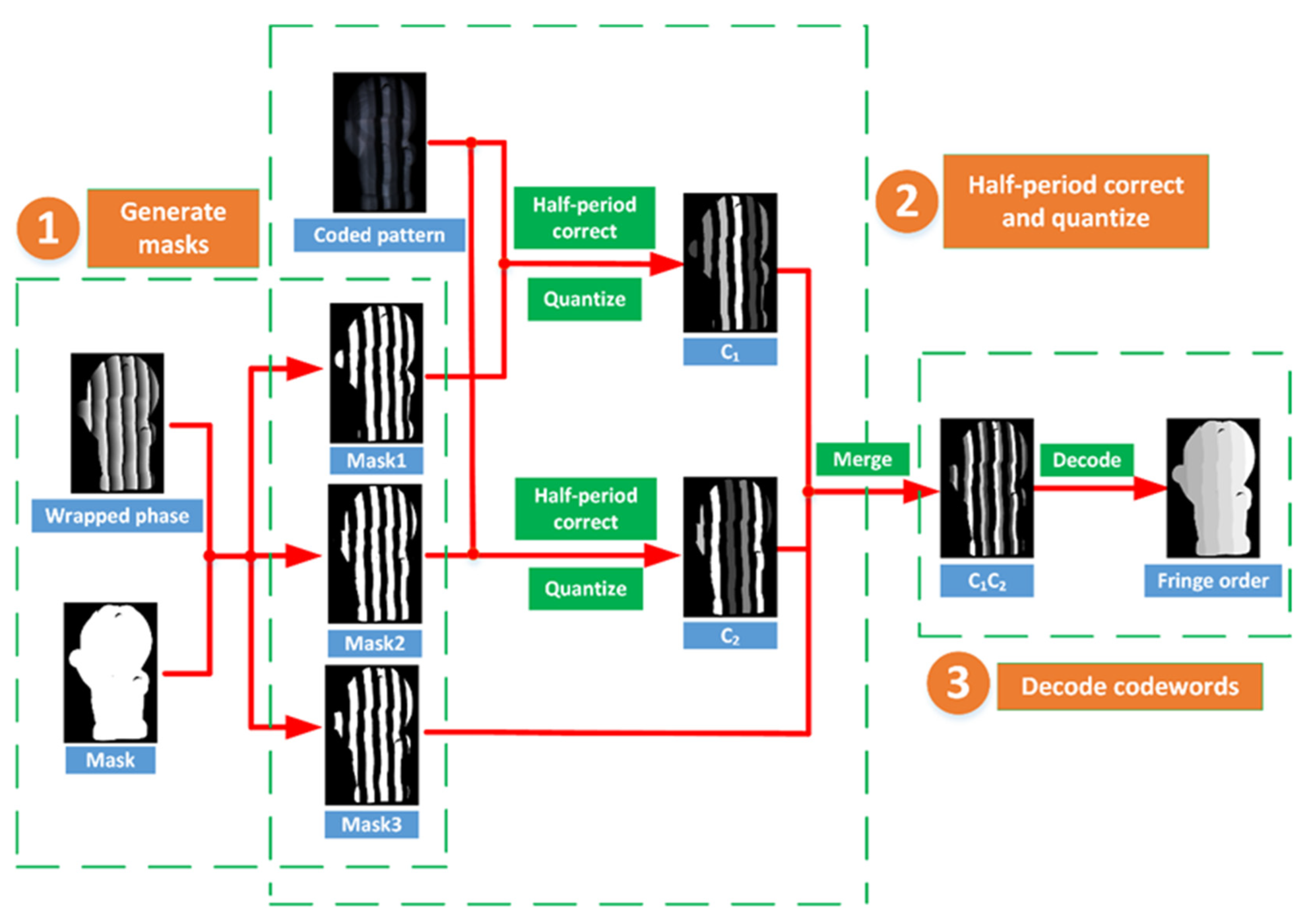
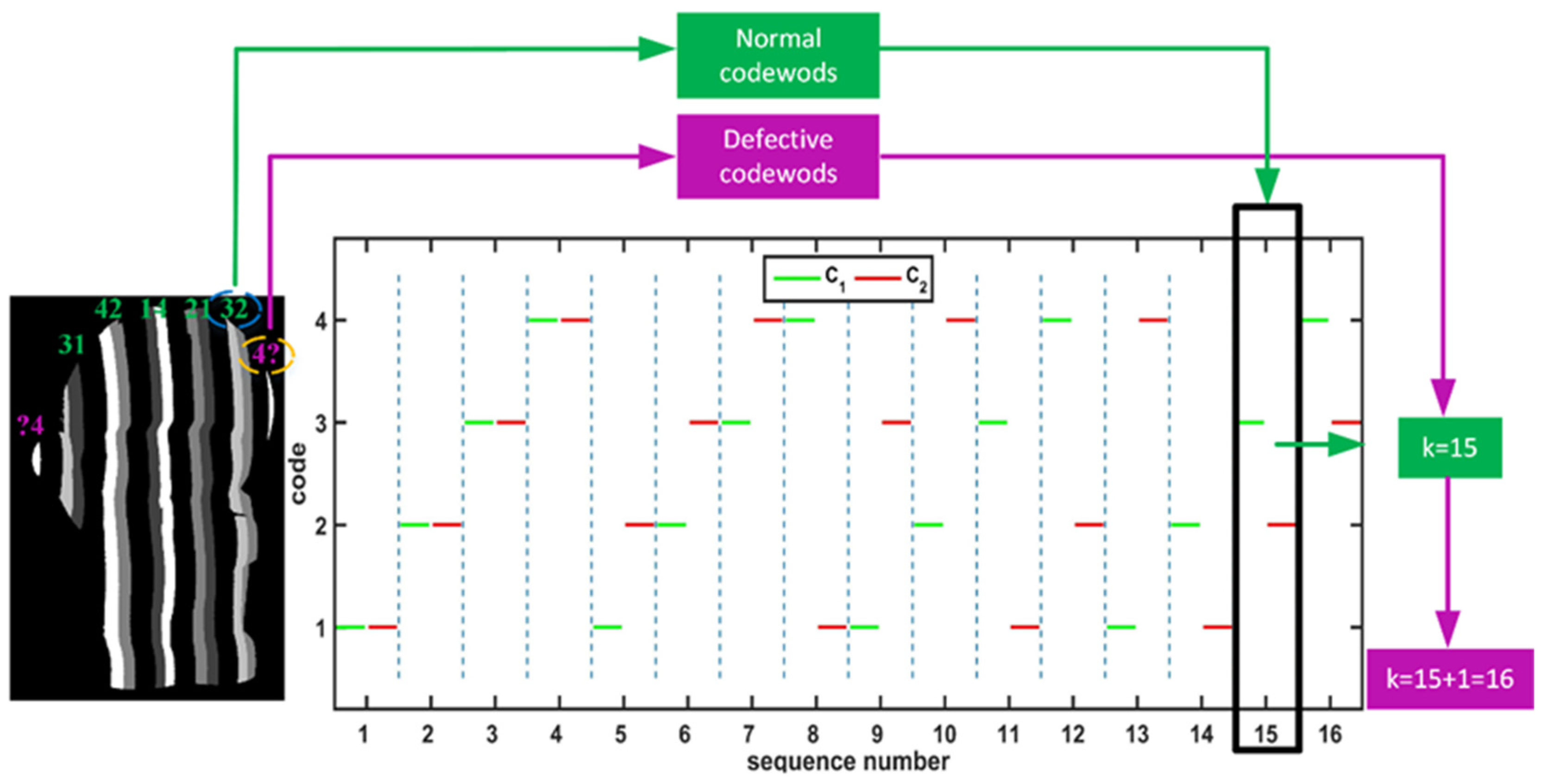
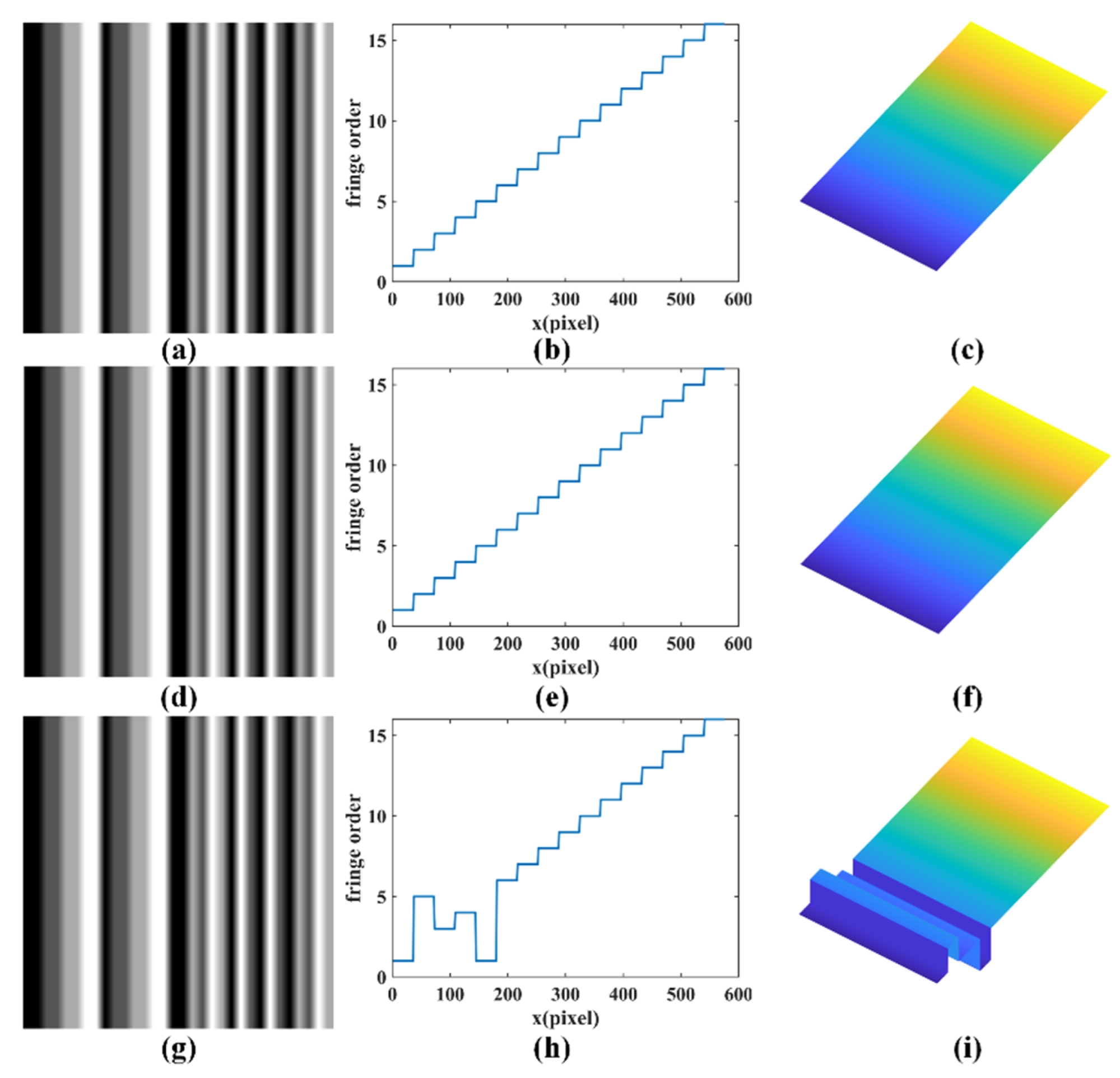
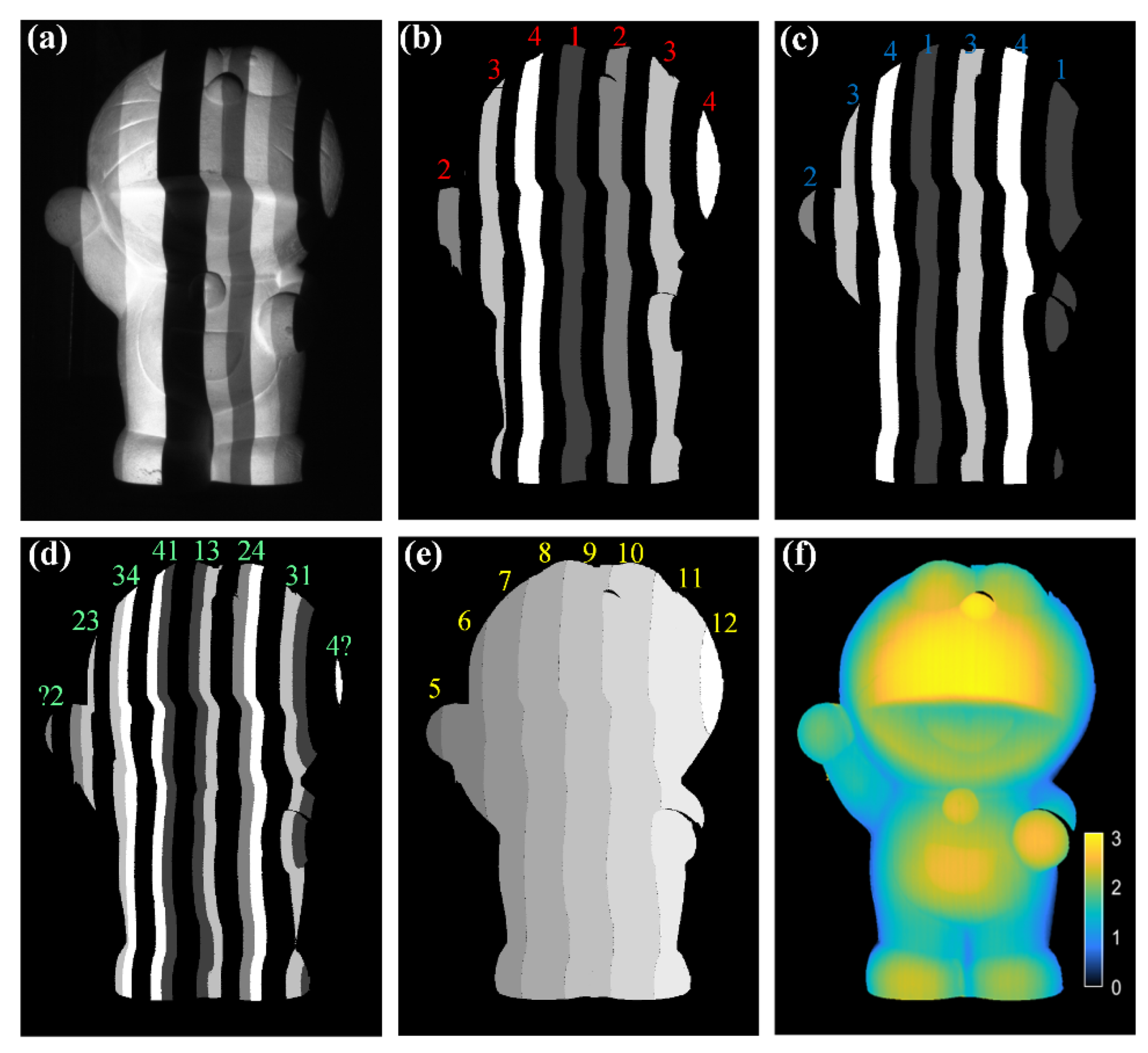
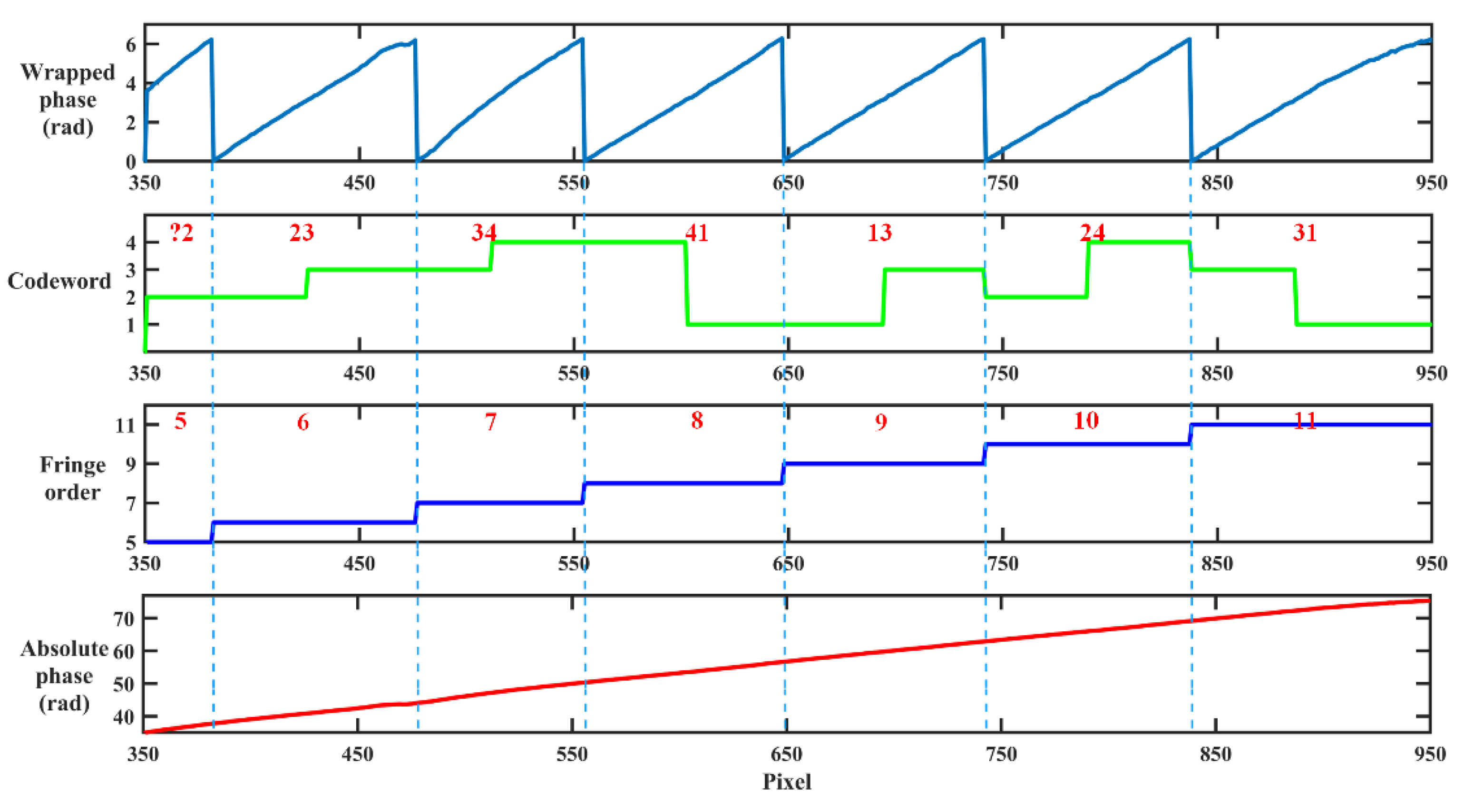
2.2.1. Coding Strategy
2.2.2. Unwrapping Strategy
3. Simulation
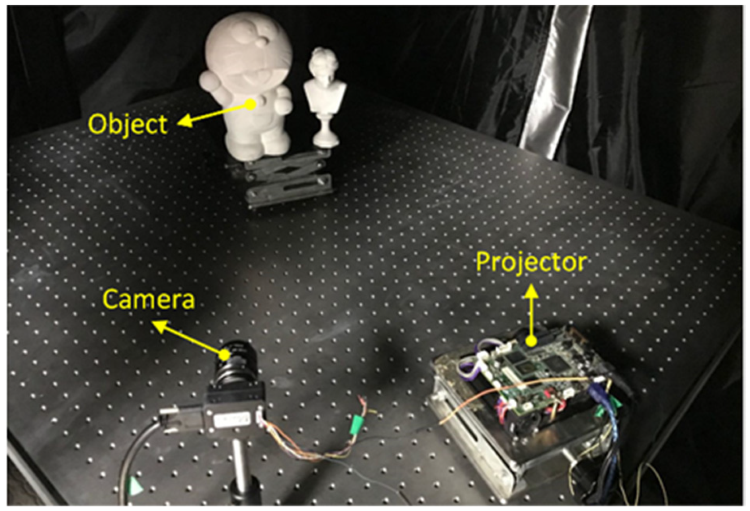
4. Experiments
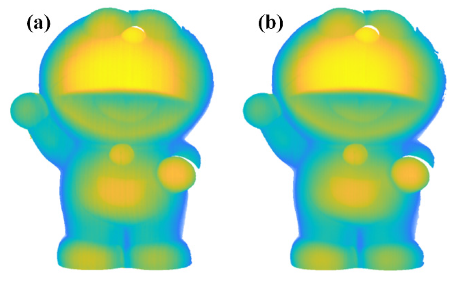
4.1. Measurement of Complex Object
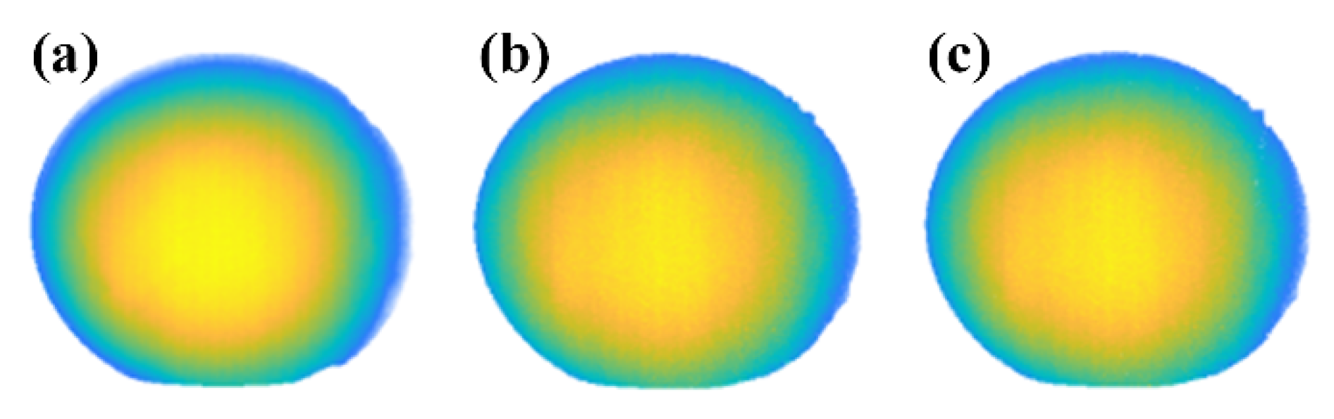
4.2. Measurement of the Standard Ball
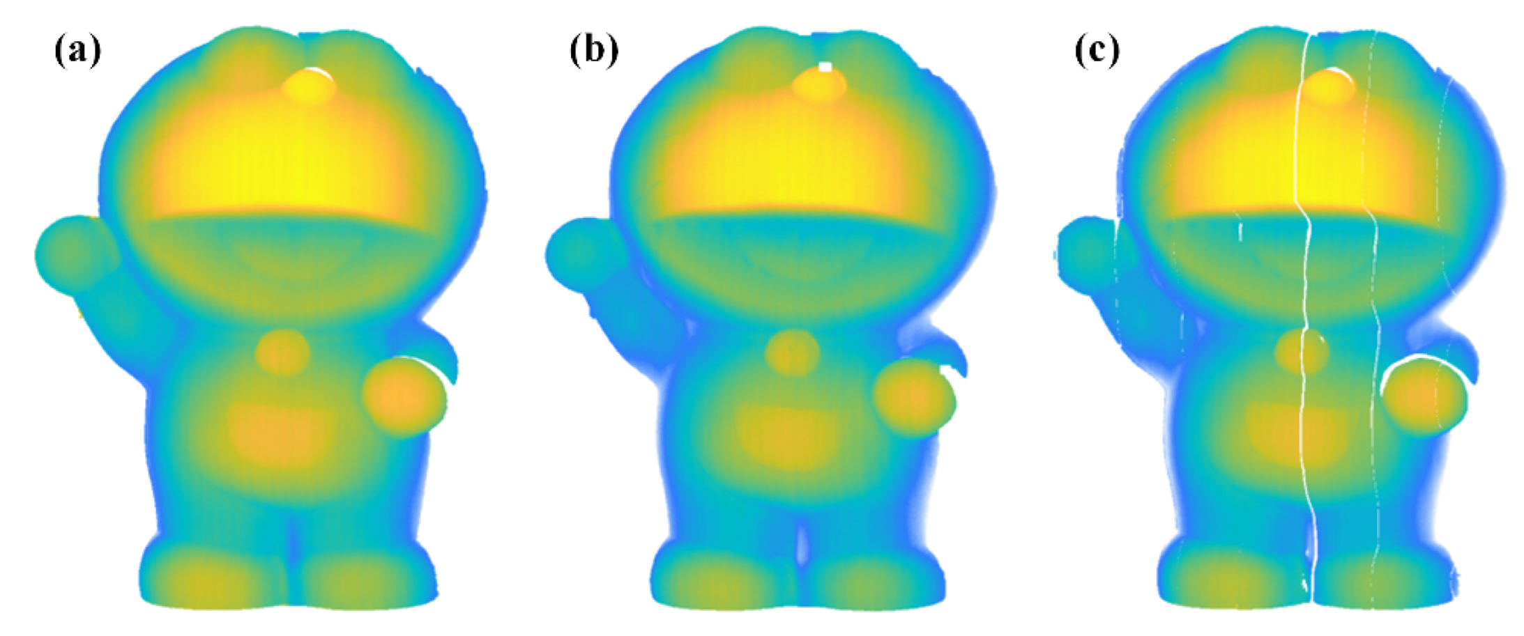
4.3. Measurement under Defocused Scenes
5. Conclusions
Author Contributions
Funding
Institutional Review Board Statement
Informed Consent Statement
Data Availability Statement
Conflicts of Interest
References
- Zhong, K.; Li, Z.; Zhou, X.; Li, Y.; Shi, Y.; Wang, C. Enhanced phase measurement profilometry for industrial 3D inspection automation. Int. J. Adv. Manuf. Technol. 2014, 76, 1563–1574. [Google Scholar] [CrossRef]
- Heist, S.; Zhang, C.; Reichwald, K.; Kuhmstedt, P.; Notni, G.; Tunnermann, A. 5D hyperspectral imaging: Fast and accurate measurement of surface shape and spectral characteristics using structured light. Opt. Express 2018, 26, 23366–23379. [Google Scholar] [CrossRef]
- Inanç, A.; Kösoğlu, G.; Yüksel, H.; Naci Inci, M. 3-D optical profilometry at micron scale with multi-frequency fringe projection using modified fibre optic Lloyd’s mirror technique. Opt. Lasers Eng. 2018, 105, 14–26. [Google Scholar] [CrossRef]
- Van der Jeught, S.; Dirckx, J.J.J. Real-time structured light profilometry: A review. Opt. Lasers Eng. 2016, 87, 18–31. [Google Scholar] [CrossRef]
- Zuo, C.; Huang, L.; Zhang, M.; Chen, Q.; Asundi, A. Temporal phase unwrapping algorithms for fringe projection profilometry: A comparative review. Opt. Lasers Eng. 2016, 85, 84–103. [Google Scholar] [CrossRef]
- Zhang, S. High-speed 3D shape measurement with structured light methods: A review. Opt. Lasers Eng. 2018, 106, 119–131. [Google Scholar] [CrossRef]
- Zhang, S. Absolute phase retrieval methods for digital fringe projection profilometry A review. Opt. Lasers Eng. 2018, 107, 28–37. [Google Scholar] [CrossRef]
- Xu, J.; Zhang, S. Status, challenges, and future perspectives of fringe projection profilometry. Opt. Lasers Eng. 2020, 135, 106193. [Google Scholar] [CrossRef]
- Cai, B.; Wang, Y.; Wang, K.; Ma, M.; Chen, X. Camera Calibration Robust to Defocus Using Phase-Shifting Patterns. Sensors 2017, 17, 2361. [Google Scholar] [CrossRef] [Green Version]
- Lu, P.; Sun, C.; Liu, B.; Wang, P. Accurate and robust calibration method based on pattern geometric constraints for fringe projection profilometry. Appl. Opt. 2017, 56, 784–794. [Google Scholar] [CrossRef]
- Cai, B.; Wang, Y.; Wu, J.; Wang, M.; Li, F.; Ma, M.; Chen, X.; Wang, K. An effective method for camera calibration in defocus scene with circular gratings. Opt. Lasers Eng. 2019, 114, 44–49. [Google Scholar] [CrossRef]
- Takeda, M.; Mutoh, K. Fourier transform profilometry for the automatic measurement of 3-D object shapes. Appl. Opt. 1983, 22, 3977. [Google Scholar] [CrossRef] [PubMed]
- Zhang, Z.; Jing, Z.; Wang, Z.; Kuang, D. Comparison of Fourier transform, windowed Fourier transform, and wavelet transform methods for phase calculation at discontinuities in fringe projection profilometry. Opt. Lasers Eng. 2012, 50, 1152–1160. [Google Scholar] [CrossRef]
- Kemao, Q. Applications of windowed Fourier fringe analysis in optical measurement: A review. Opt. Lasers Eng. 2015, 66, 67–73. [Google Scholar] [CrossRef]
- Zuo, C.; Feng, S.; Huang, L.; Tao, T.; Yin, W.; Chen, Q. Phase shifting algorithms for fringe projection profilometry: A review. Opt. Lasers Eng. 2018, 109, 23–59. [Google Scholar] [CrossRef]
- Tao, B.; Liu, Y.; Huang, L.; Chen, G.; Chen, B. 3D reconstruction based on photoelastic fringes. Concurr. Comput. Pract. Exp. 2021, 34, e6481. [Google Scholar] [CrossRef]
- Wang, Y.; Cai, J.; Liu, Y.; Chen, X.; Wang, Y. Motion-induced error reduction for phase-shifting profilometry with phase probability equalization. Opt. Lasers Eng. 2022, 156, 107088. [Google Scholar] [CrossRef]
- Wang, Y.; Cai, J.; Zhang, D.; Chen, X.; Wang, Y. Nonlinear Correction for Fringe Projection Profilometry With Shifted-Phase Histogram Equalization. IEEE Trans. Instrum. Meas. 2022, 71, 5005509. [Google Scholar] [CrossRef]
- Cui, H. Reliability-guided phase-unwrapping algorithm for the measurement of discontinuous three-dimensional objects. Opt. Eng. 2011, 50, 063602. [Google Scholar] [CrossRef]
- Zhang, S.; Li, X.; Yau, S.T. Multilevel quality-guided phase unwrapping algorithm for real-time three-dimensional shape reconstruction. Appl. Opt. 2007, 46, 50–57. [Google Scholar] [CrossRef]
- Zhong, H.; Tang, J.; Zhang, S.; Chen, M. An Improved Quality-Guided Phase-Unwrapping Algorithm Based on Priority Queue. IEEE Geosci. Remote Sens. Lett. 2011, 8, 364–368. [Google Scholar] [CrossRef]
- Wu, J.; Zhou, Z.; Liu, Q.; Wang, Y.; Wang, Y.; Gu, Y.; Chen, X. Two-wavelength phase-shifting method with four patterns for three-dimensional shape measurement. Opt. Eng. 2020, 59, 024107. [Google Scholar] [CrossRef]
- Liu, K.; Wang, Y.; Lau, D.L.; Hao, Q.; Hassebrook, L.G. Dual-frequency pattern scheme for high speed 3-D shape measurement. Opt. Express 2010, 18, 5229–5244. [Google Scholar] [CrossRef] [PubMed] [Green Version]
- Song, L.; Dong, X.; Xi, J.; Yu, Y.; Yang, C. A new phase unwrapping algorithm based on Three Wavelength Phase Shift Profilometry method. Opt. Laser Technol. 2013, 45, 319–329. [Google Scholar] [CrossRef]
- Zhang, Q.; Su, X.; Xiang, L.; Sun, X. 3-D shape measurement based on complementary Gray-code light. Opt. Lasers Eng. 2012, 50, 574–579. [Google Scholar] [CrossRef]
- Zheng, D.; Da, F.; Kemao, Q.; Seah, H.S. Phase-shifting profilometry combined with Gray-code patterns projection: Unwrapping error removal by an adaptive median filter. Opt. Express 2017, 25, 4700–4713. [Google Scholar]
- Wang, Y.; Zhang, S. Novel phase-coding method for absolute phase retrieval. Opt. Lett. 2012, 37, 2067–2069. [Google Scholar] [CrossRef]
- Chen, X.; Wang, Y.; Wang, Y.; Ma, M.; Zeng, C. Quantized phase coding and connected region labeling for absolute phase retrieval. Opt. Express 2016, 24, 28613–28624. [Google Scholar] [CrossRef]
- Chen, X.; Wu, J.; Fan, R.; Liu, Q.; Xiao, Y.; Wang, Y.; Wang, Y. Two-digit phase-coding strategy for fringe projection profilometry. IEEE Trans. Instrum. Meas. 2020, 91, 242–256. [Google Scholar] [CrossRef]
- Porras-Aguilar, R.; Falaggis, K.; Ramos-Garcia, R. Optimum projection pattern generation for grey-level coded structured light illumination systems. Opt. Lasers Eng. 2017, 91, 242–256. [Google Scholar] [CrossRef]
- Chen, X.; Chen, S.; Luo, J.; Ma, M.; Wang, Y.; Wang, Y.; Chen, L. Modified Gray-Level Coding Method for Absolute Phase Retrieval. Sensors 2017, 17, 2383. [Google Scholar] [CrossRef] [PubMed] [Green Version]
- Cai, B.; Yang, Y.; Wu, J.; Wang, Y.; Wang, M.; Chen, X.; Wang, K.; Zhang, L. An improved gray-level coding method for absolute phase measurement based on half-period correction. Opt. Lasers Eng. 2020, 128, 106012. [Google Scholar] [CrossRef]
- Ma, M.; Yao, P.; Deng, J.; Deng, H.; Zhang, J.; Zhong, X. A morphology phase unwrapping method with one code grating. Rev. Sci. Instrum. 2018, 89, 073112. [Google Scholar] [CrossRef]
- Wang, Y.; Liu, L.; Wu, J.; Chen, X.; Wang, Y. Spatial binary coding method for stripe-wise phase unwrapping. Appl. Opt. 2020, 59, 4279–4285. [Google Scholar] [CrossRef]
- Wu, Z.; Guo, W.; Zhang, Q. High-speed three-dimensional shape measurement based on shifting Gray-code light. Opt. Express 2019, 27, 22631–22644. [Google Scholar] [CrossRef]
- Wu, Z.; Zuo, C.; Guo, W.; Tao, T.; Zhang, Q. High-speed three-dimensional shape measurement based on cyclic complementary Gray-code light. Opt. Express 2019, 27, 1283–1297. [Google Scholar] [CrossRef] [PubMed]
- Tang, C.; Hou, C.; Song, Z. Defocus map estimation from a single image via spectrum contrast. Opt. Lett. 2013, 38, 1706–1708. [Google Scholar] [CrossRef] [PubMed] [Green Version]


| k | 1 | 2 | 3 | 4 | 5 | 6 | 7 | 8 | 9 | 10 | 11 | 12 | 13 | 14 | 15 | 16 |
|---|---|---|---|---|---|---|---|---|---|---|---|---|---|---|---|---|
| C1 | 1 | 2 | 3 | 4 | 1 | 2 | 3 | 4 | 1 | 2 | 3 | 4 | 1 | 2 | 3 | 4 |
| C2 | 1 | 2 | 3 | 4 | 2 | 3 | 4 | 1 | 3 | 4 | 1 | 2 | 4 | 1 | 2 | 3 |
| C1C2 | 11 | 22 | 33 | 44 | 12 | 23 | 34 | 41 | 13 | 24 | 31 | 42 | 14 | 21 | 32 | 43 |
| Method | RMSE (rad) |
|---|---|
| The proposed method | 0.0066 |
| Ref. [32] | 0.0064 |
Publisher’s Note: MDPI stays neutral with regard to jurisdictional claims in published maps and institutional affiliations. |
© 2022 by the authors. Licensee MDPI, Basel, Switzerland. This article is an open access article distributed under the terms and conditions of the Creative Commons Attribution (CC BY) license (https://creativecommons.org/licenses/by/4.0/).
Share and Cite
Ran, Z.; Tao, B.; Zeng, L.; Chen, X. Half-Period Gray-Level Coding Strategy for Absolute Phase Retrieval. Photonics 2022, 9, 492. https://doi.org/10.3390/photonics9070492
Ran Z, Tao B, Zeng L, Chen X. Half-Period Gray-Level Coding Strategy for Absolute Phase Retrieval. Photonics. 2022; 9(7):492. https://doi.org/10.3390/photonics9070492
Chicago/Turabian StyleRan, Zipeng, Bo Tao, Liangcai Zeng, and Xiangcheng Chen. 2022. "Half-Period Gray-Level Coding Strategy for Absolute Phase Retrieval" Photonics 9, no. 7: 492. https://doi.org/10.3390/photonics9070492