Correction of Distorted Wavefront Using Dual Liquid Crystal Spatial Light Modulators

Abstract
:1. Introduction
2. Theoretical Research
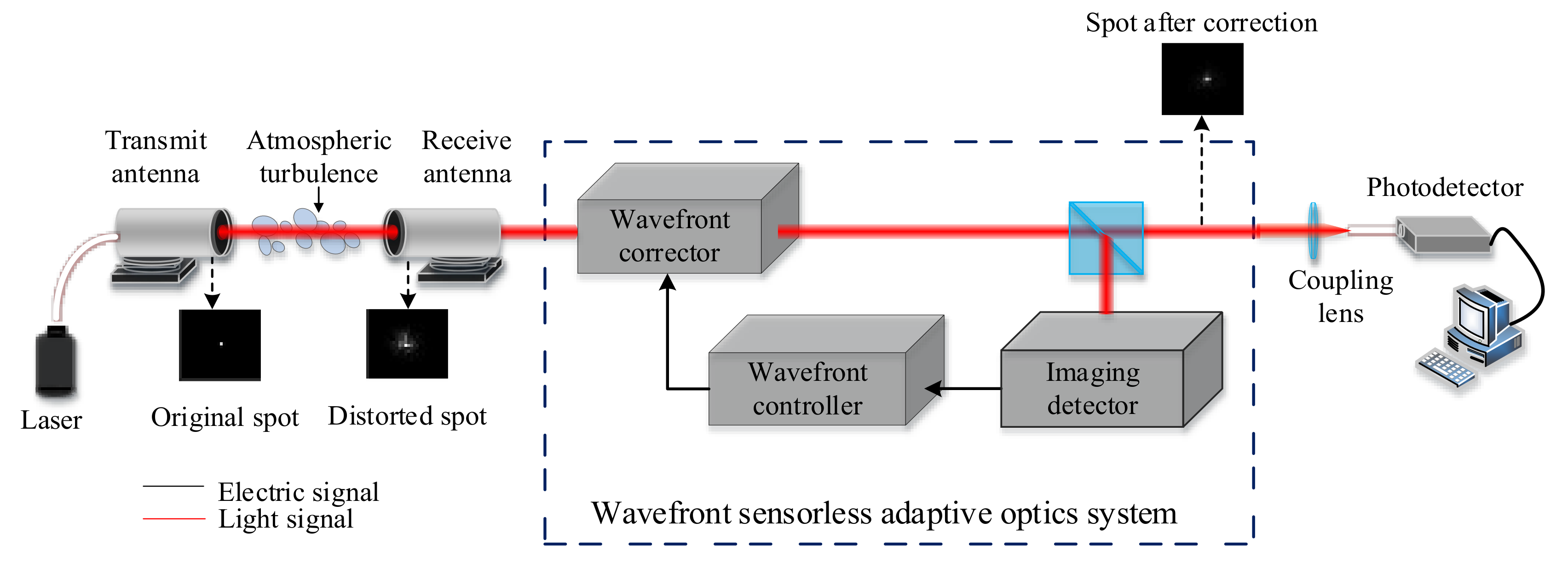
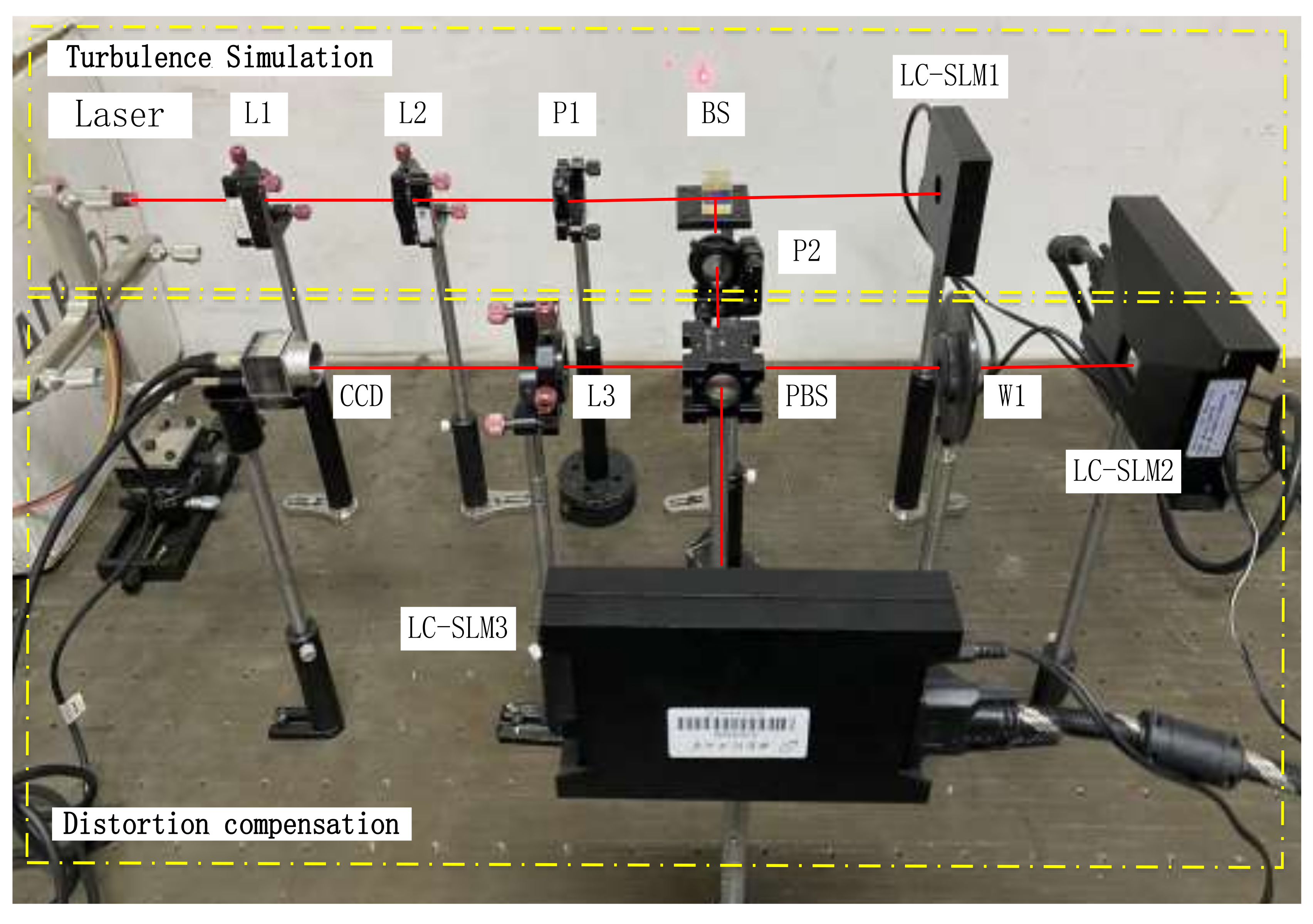
2.1. System Structure
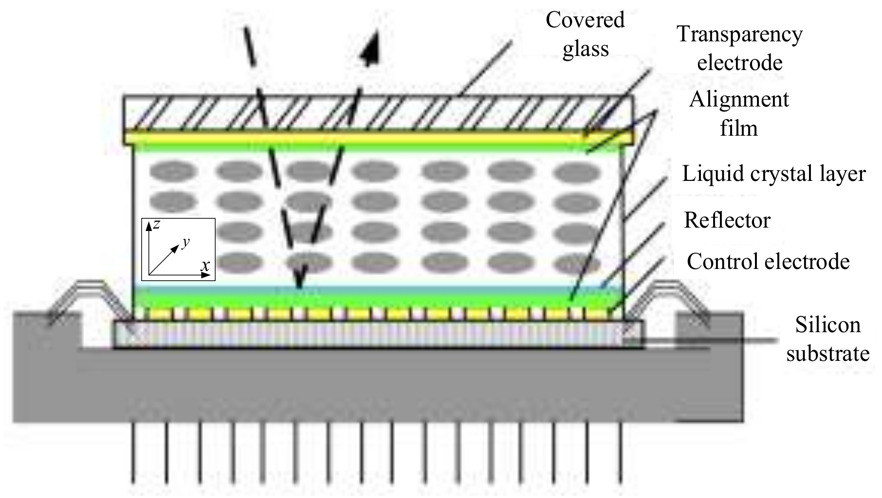
2.2. LC-SLM Correction Principle
2.3. LC-SLM Energy Compensation
2.4. GS Algorithm
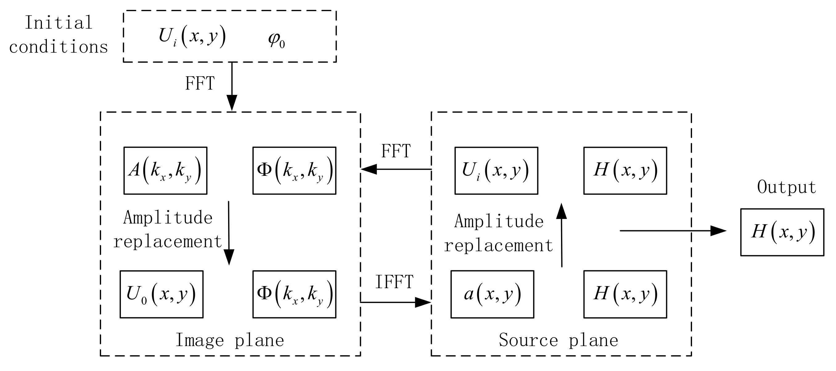
- (1)
- Select the ideal optical field amplitude without wavefront distortion as the amplitude of the input optical field, select the ideal phase as the initial random phase, and the two forms of the optical field as the input optical field for the diffraction calculation.
- (2)
- Calculate the diffraction transmission of the light field to obtain its transform-domain amplitude spectrum and phase spectrum .
- (3)
- Replace with the distorted beam amplitude spectrum to obtain a new complex amplitude for the light field.
- (4)
- Perform the inverse diffraction operation on the light field to obtain the spatial domain amplitude spectrum and phase spectrum .
- (5)
- Replace with the amplitude spectrum of the initial ideal light field to obtain the initial light-field expression for the next iteration of the loop. When certain iteration conditions are met or the defined number of cycle iterations is reached, the calculation is terminated, and the reconstructed beam distortion phase can be obtained.
- (6)
- The corresponding distortion phase of the simulated atmospheric turbulence is .
3. Simulation and Experiment
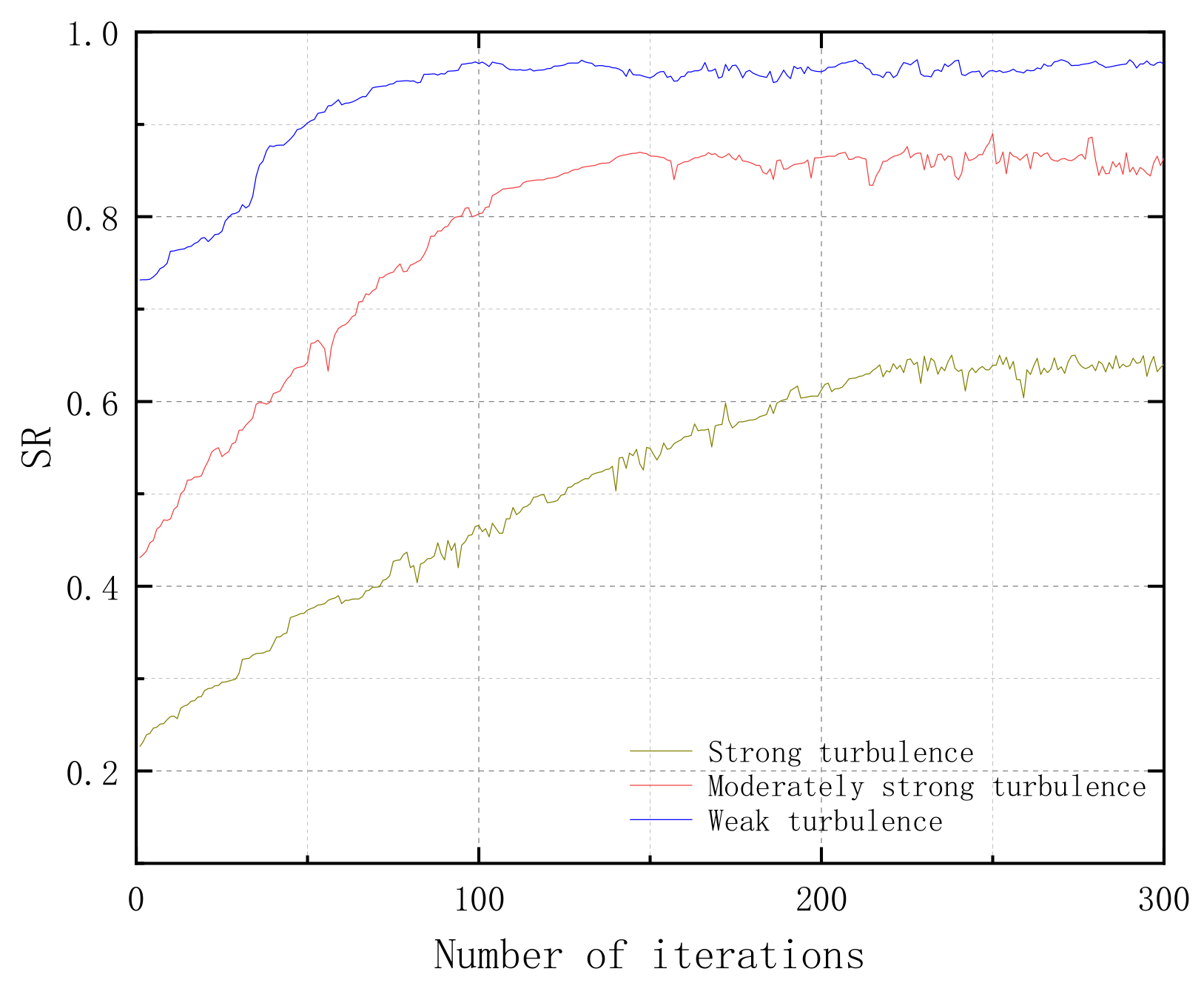
3.1. Evaluation Indicators
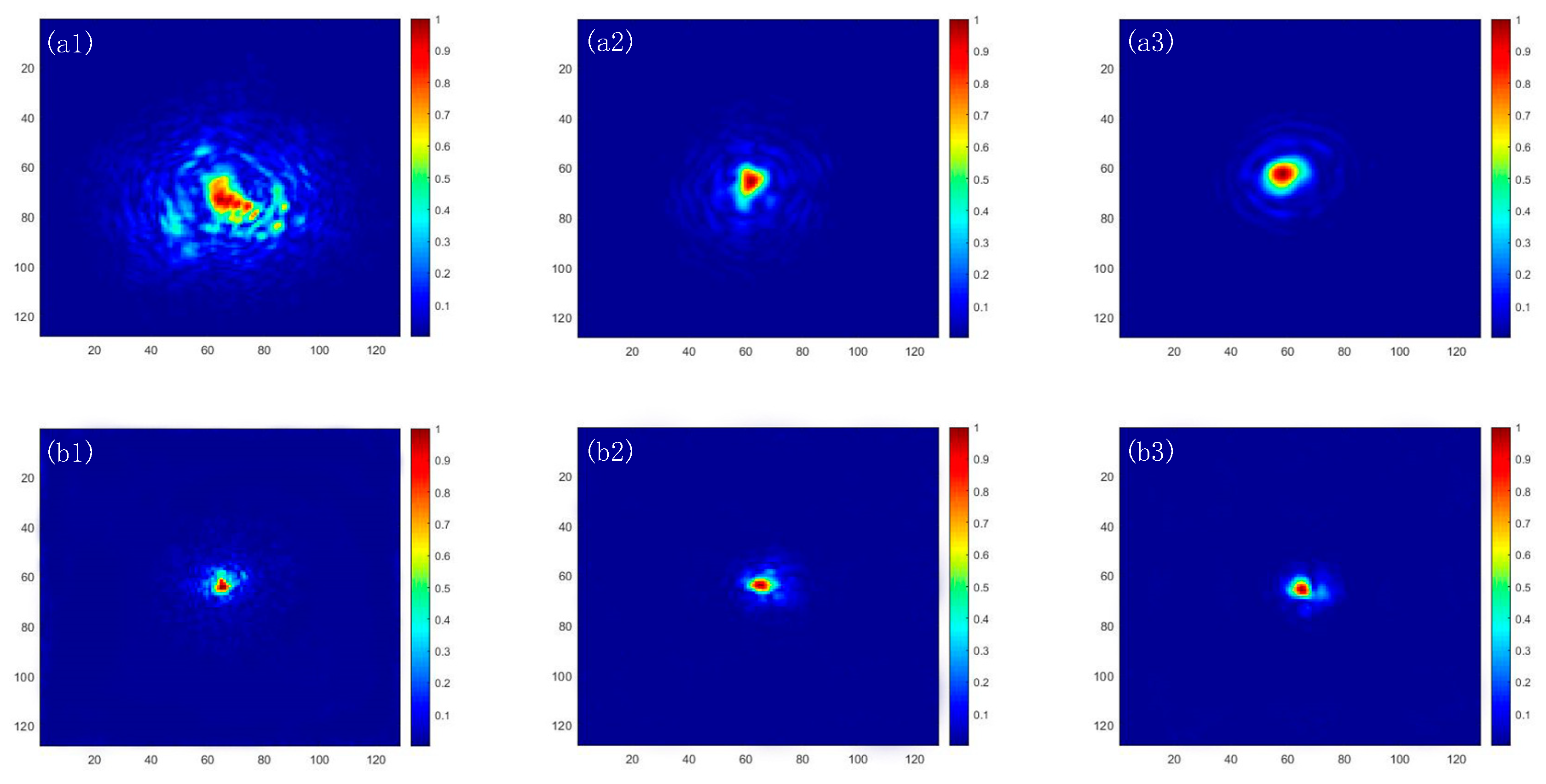
3.2. Numerical Simulation
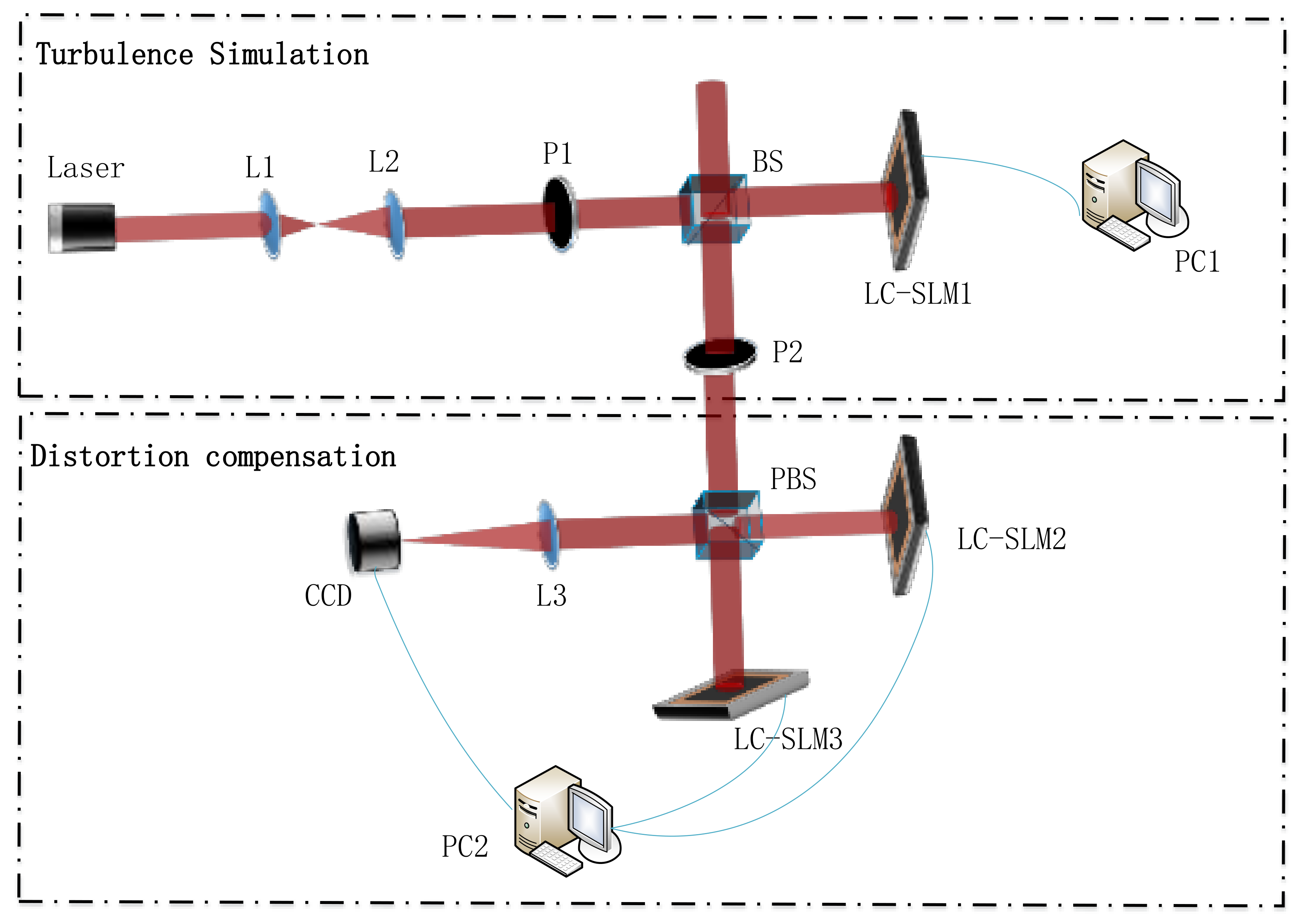
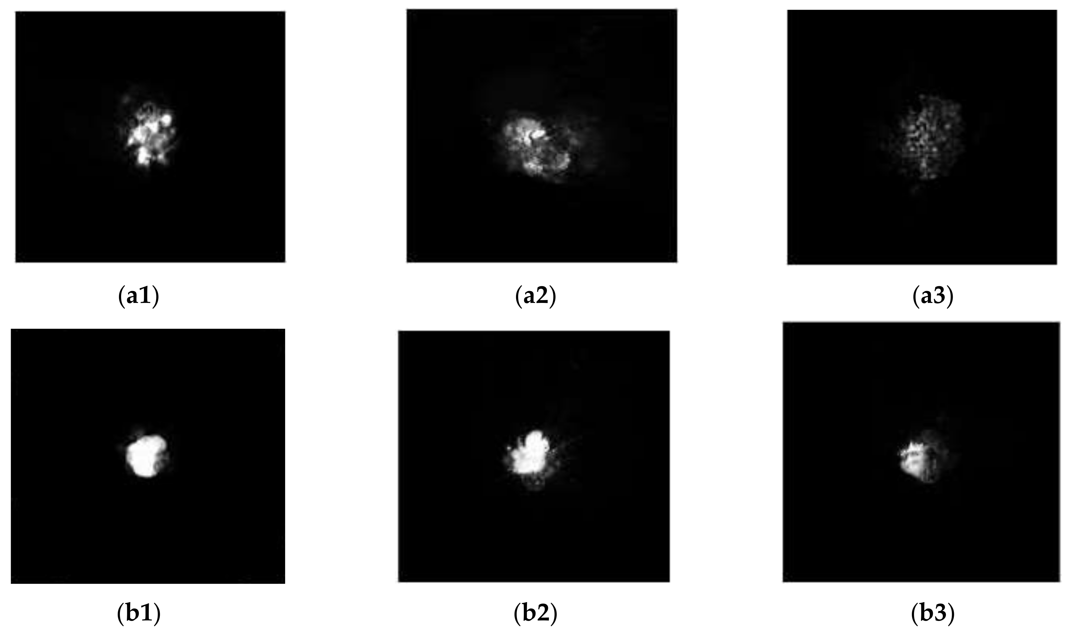
3.3. Experimental Study
4. Conclusions
Author Contributions
Funding
Institutional Review Board Statement
Informed Consent Statement
Data Availability Statement
Conflicts of Interest
References
- Restaino, S.R.; Andrews, J.R.; Martinez, T.; Santiago, F.; Wick, D.V.; Wilcox, C.C. Adaptive optics using MEMS and liquid crystal devices. J. Opt. A Pure Appl. Opt. 2008, 10, 064006. [Google Scholar] [CrossRef]
- Farrell, T.C. Fast simulation of Strehl loss due to phase aberration for the sizing of adaptive optics in laser communications system design. Appl. Opt. 2013, 53, 64–70. [Google Scholar] [CrossRef] [PubMed]
- Noll, R.J. Zernike polynomials and atmospheric turbulence*. J. Opt. Soc. Am. 1976, 66, 207–211. [Google Scholar] [CrossRef]
- Lio, G.; Ferraro, A. LIDAR and Beam Steering Tailored by Neuromorphic Metasurfaces Dipped in a Tunable Surrounding Medium. Photonics 2021, 8, 65. [Google Scholar] [CrossRef]
- Roberts, J.E.; Dekany, R.G.; Burruss, R.S.; Baranec, C.; Bouchez, A.; Croner, E.E.; Guiwits, S.R.; Hale, D.D.S.; Henning, J.R.; Palmer, D.L.; et al. Results from the PALM-3000 high-order adaptive optics system. In Proceedings of the SPIE—The International Society for Optical Engineering, Amsterdam, The Netherlands, 13 September 2012; Volume 8447. [Google Scholar]
- Dou, R.; Giles, M.K. Closed-loop adaptive-optics system with a liquid-crystal television as a phase retarder. Opt. Lett. 1995, 20, 1583–1585. [Google Scholar] [CrossRef] [PubMed]
- Kirsch, J.C.; Gregory, D.A.; Thie, M.W.; Jones, B.K. Modulation characteristics of the Epson liquid crystal television. Opt. Eng. 1992, 31, 963–970. [Google Scholar] [CrossRef]
- Casasent, D. Spatial light modulators. Proc. IEEE 1977, 65, 143–157. [Google Scholar] [CrossRef]
- Hori, Y.; Asai, K.; Fukai, M. Field-controllable liquid-crystal phase grating. IEEE Trans. Electron Devices 1979, 26, 1734–1737. [Google Scholar] [CrossRef]
- Mcglamery, B.L. Restoration of Turbulence-Degraded Images. J. Opt. Soc. Am. 1967, 57, 293–296. [Google Scholar] [CrossRef]
- Dayton, D.; Gonglewski, J.; Restaino, S.; Martin, J.; Phillips, J.; Hartman, M.; Browne, S.; Kervin, P.; Snodgrass, J.; Heimann, N.; et al. Demonstration of new technology MEMS and liquid crystal adaptive optics on bright astronomical objects and satellites. Opt. Express 2002, 10, 1508–1519. [Google Scholar] [CrossRef] [PubMed]
- Gu, D.-F.; Winker, B.; Wen, B.; Taber, D.; Brackley, A.; Wirth, A.; Albanese, M.; Landers, F. Wavefront Control with a Spatial Light Modulator Containing Dual-Frequency Liquid Crystal. Available online: https://www.spiedigitallibrary.org/conference-proceedings-of-spie/5553/0000/Wavefront-control-with-a-spatial-light-modulator-containing-dual-frequency/10.1117/12.562088.short?SSO=1 (accessed on 6 May 2022).
- Xuan, L.; Li, D.Y.; Liu, Y.G. The application prospect of liquid crystal adaptive optics in astronomical research. Liq. Cryst. Disp. 2018, 30, 1–9. [Google Scholar]
- Love, G. Wave-front correction and production of Zernike modes with a liquid-crystal spatial light modulator. Appl. Opt. 1997, 36, 1517–1520. [Google Scholar] [CrossRef] [PubMed]
- Huang, H.; Inoue, T.; Hara, T. An adaptive wavefront control system using a high-resolution liquid crystal spatial light modulator. In Proceedings of the Adaptive Optics and Applications III, Beijing, China, 8–11 November 2004. [Google Scholar]
- Li, X.Z.; Han, C.S.; Wen, M.; Sun, Z.W.; Zhao, Q.L.; Jiang, X.N. Research on wavefront distortion compensation based on liquid crystal space light modulator. Laser Infrared 2011, 41, 187–191. [Google Scholar]
- Wang, Z.H.; Yu, X. Measuring of the phase modulation of liquid crystal spatial light modulator and correcting of the wavefront. Opt. Tech. 2005, 201, 196–199+201. [Google Scholar]
- Liesl, B.; Litvin, I.A.; Forbes, A. Simulating atmospheric turbulence using a phase-only spatial light modulator. S. Afr. J. Sci. 2008, 3, 129–134. [Google Scholar]
- Liu, Y.J.; Xuan, L.; Cao, Z.L.; Li, D.Y.; Mu, Q.Q.; Hu, L.F.; Lu, X.H. Research on high-precision pure-phase liquid crystal spatial light modulator. J. Opt. 2005, 25, 1682–1686. [Google Scholar]
- Fried, D.L. Time-delay-induced mean-square error in adaptive optics. J. Opt. Soc. Am. A 1990, 7, 1224–1225. [Google Scholar] [CrossRef]
- Zhang, X.; Hu, L.; Cao, Z.; Mu, Q.; Li, D.; Xuan, L. Improve the accuracy of interaction matrix measurement for liquid-crystal adaptive optics systems. Opt. Express 2014, 22, 14221–14228. [Google Scholar] [CrossRef] [PubMed]
- Akhmanov, S.A.; Nikitin, S.Y. Physical Optics; Clarendon Press: London, UK, 1997. [Google Scholar]
- Ren, Y.; Huang, H.; Yang, J.-Y.; Yan, Y.; Ahmed, N.; Yue, Y.; Willner, A.E.; Birnbaum, K.; Choi, J.; Erkmen, B.; et al. Correction of Phase Distortion of an OAM Mode using GS Algorithm based Phase Retrieval. In Proceedings of the CLEO: Science and Innovations 2012, San Jose, CA, USA, 6–11 May 2012. [Google Scholar] [CrossRef]
- Han, L.Q.; Wang, Z.B. Fiber coupling efficiency and Strehl ratio of space optical communication under adaptive optics correction. Infrared Laser Eng. 2013, 42, 125–129. [Google Scholar]
- Zhang, H.-X.; Zhang, J.; Qiao, Y.-J.; Si, J.-S. Wavefront generation and error compensation by liquid crystal spatial light modulator. J. Optoelectron. Laser 2013, 24, 838–842. [Google Scholar]


| Equipment | Model | Parameters |
|---|---|---|
| LC-SLM | RL-SLM-R2 | Target surface size: ; cell size: 12.3 μm; reflectivity: ; refresh rate: 60 Hz; data interface: VGA/DVI; phase modulation capability: 0~2 @532 nm; working wavelength: 400~700 nm |
| CCD | MV-EM series Gigabit Ethernet Industrial Camera | Interface: GigE; pixel size: ; frame rate: 8 fps; exposure time: ; exposure method: frame exposure; synchronization mode: external trigger or continuous acquisition |
Publisher’s Note: MDPI stays neutral with regard to jurisdictional claims in published maps and institutional affiliations. |
© 2022 by the authors. Licensee MDPI, Basel, Switzerland. This article is an open access article distributed under the terms and conditions of the Creative Commons Attribution (CC BY) license (https://creativecommons.org/licenses/by/4.0/).
Share and Cite
Wu, J.; Ke, X.; Yang, Y.; Liang, J.; Liu, M. Correction of Distorted Wavefront Using Dual Liquid Crystal Spatial Light Modulators. Photonics 2022, 9, 426. https://doi.org/10.3390/photonics9060426
Wu J, Ke X, Yang Y, Liang J, Liu M. Correction of Distorted Wavefront Using Dual Liquid Crystal Spatial Light Modulators. Photonics. 2022; 9(6):426. https://doi.org/10.3390/photonics9060426
Chicago/Turabian StyleWu, Jiali, Xizheng Ke, Yaqi Yang, Jingyuan Liang, and Mingyu Liu. 2022. "Correction of Distorted Wavefront Using Dual Liquid Crystal Spatial Light Modulators" Photonics 9, no. 6: 426. https://doi.org/10.3390/photonics9060426