Advances in Multicore Fiber Grating Sensors


Abstract
:1. Introduction
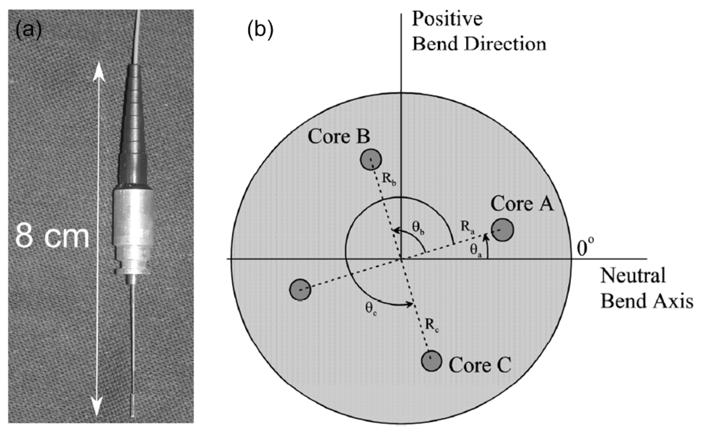
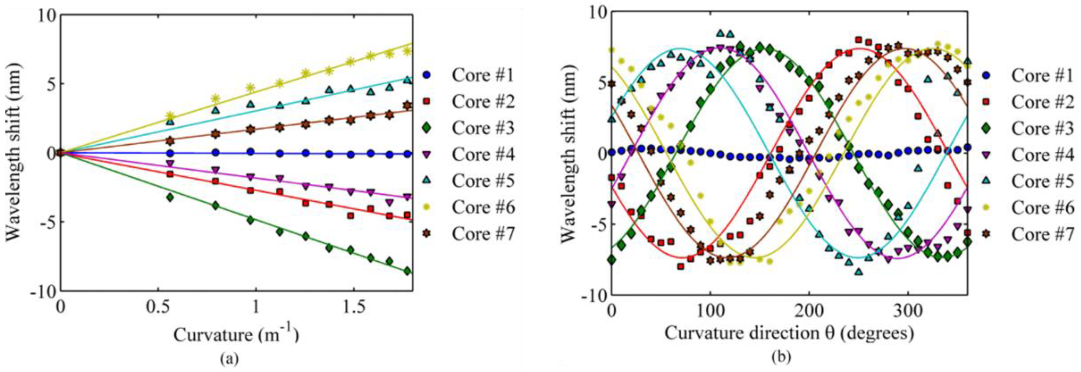
2. Bending Sensitivity in Off-Center Cores of MCF
3. MCF-Based Fiber Bragg Grating Sensors
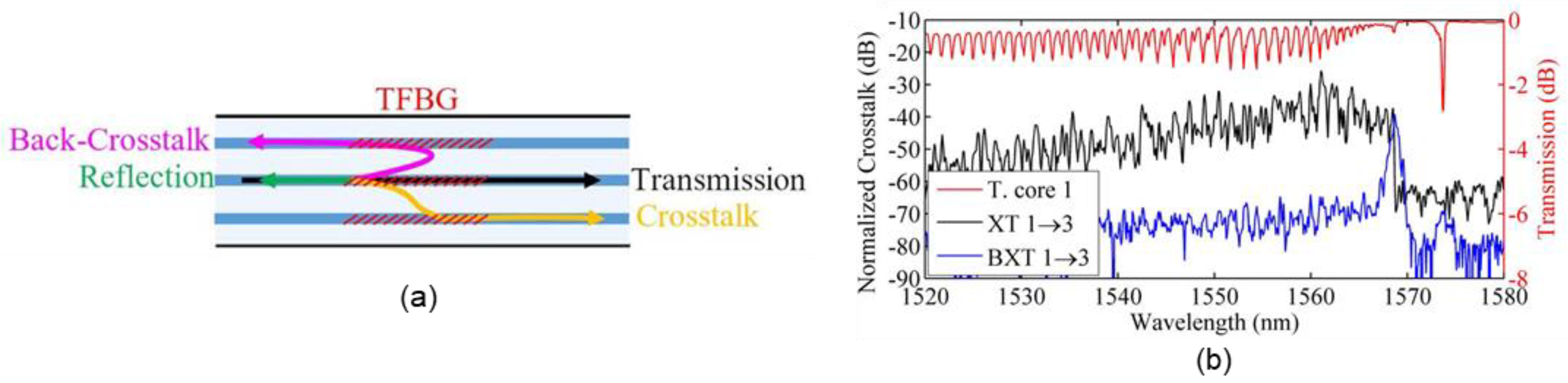
4. MCF-Based Tilted Fiber Bragg Grating Sensors
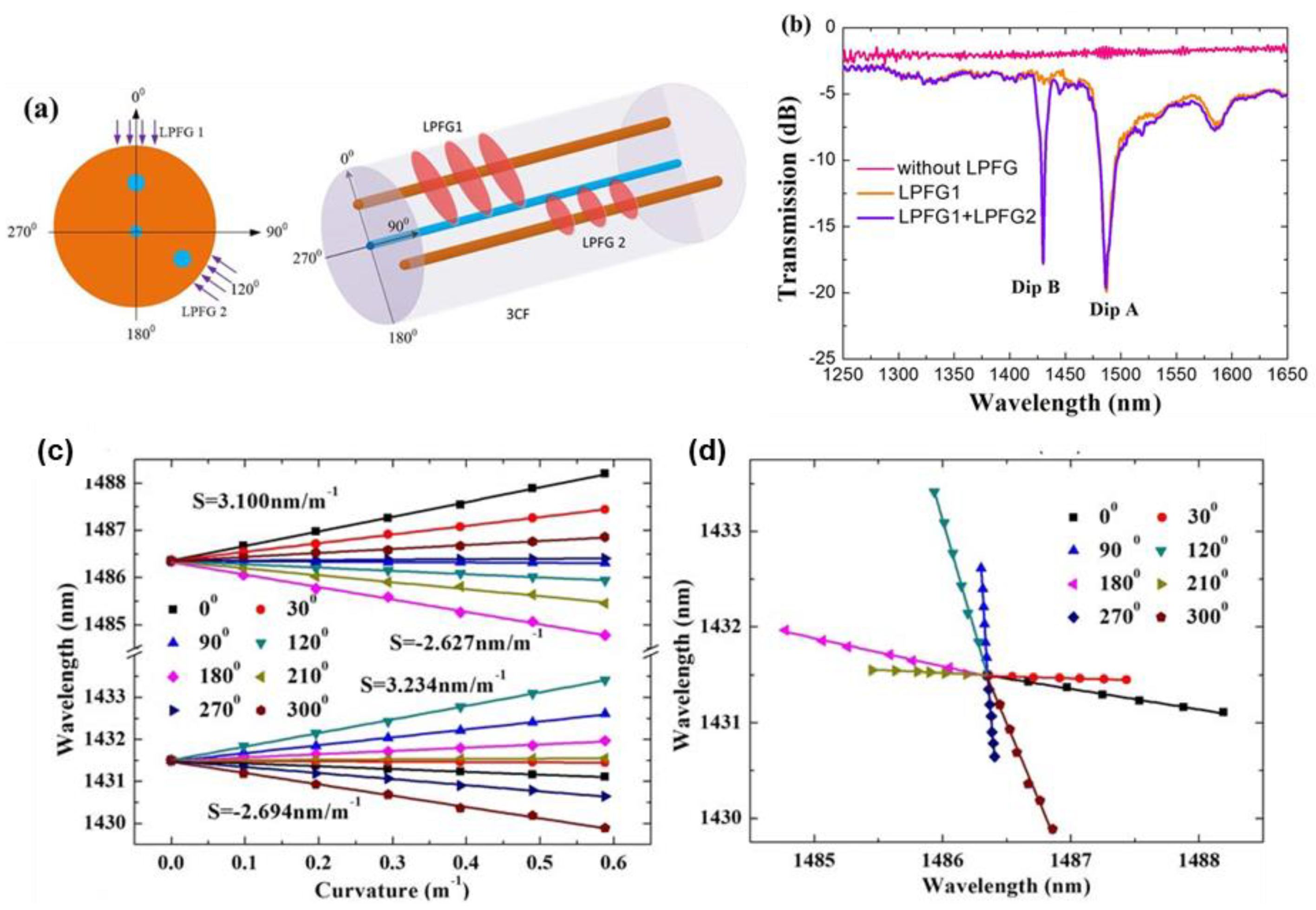
5. MCF-Based Long Period Grating Sensors
6. Discussion
7. Conclusions
Author Contributions
Funding
Data Availability Statement
Conflicts of Interest
References
- Winzer, P.J. Making spatial multiplexing a reality. Nat. Photonics 2014, 8, 345–348. [Google Scholar] [CrossRef] [Green Version]
- Van Uden, R.G.H.; Correa, R.A.; Lopez, E.A.; Huijskens, F.M.; Xia, C.; Li, G.; Schülzgen, A.; Waardt, H.; Koonen, A.M.J.; Okonkwo, C.M. Ultra-high-density spatial division multiplexing with a few-mode multicore fibre. Nat. Photonics 2014, 8, 865–870. [Google Scholar] [CrossRef] [Green Version]
- Tang, M. Multicore Fibers. In Handbook of Optical Fibers; Peng, G.D., Ed.; Springer: Singapore, 2019. [Google Scholar] [CrossRef]
- Ortiz, A.M.; Sáez, R.L. Multi-core optical fibers: Theory, applications and opportunities. In Selected Topics on Optical Fiber Technologies and Applications; IntechOpen: London, UK, 2017; pp. 63–102. [Google Scholar]
- Awaji, Y.; Saitoh, K.; Matsuo, S. Optical Fiber Telecommunications VIB: Chapter 13. Transmission Systems Using Multicore Fibers; Elsevier: Amsterdam, The Netherlands, 2013. [Google Scholar]
- Glas, P.; Naumann, M.; Schirrmacher, A.; Pertsch, T. The multicore fiber–a novel design for a diode pumped fiber laser. Opt. Commun. 1998, 151, 187–195. [Google Scholar] [CrossRef]
- Mizuno, T.; Takara, H.; Sano, A.; Miyamoto, Y. Dense space-division multiplexed transmission systems using multi-core and multi-mode fiber. J. Lightwave Technol. 2015, 34, 582–592. [Google Scholar] [CrossRef]
- Zhu, B.; Taunay, T.F.; Yan, M.F.; Fini, J.M.; Fishteyn, M.; Monberg, E.M.; Dimarcello, F.V. Seven-core multicore fiber transmissions for passive optical network. Opt. Express 2010, 18, 11117–11122. [Google Scholar] [CrossRef] [PubMed]
- Matsui, T.; Sakamoto, T.; Goto, Y.; Saito, K.; Nakajima, K.; Yamamoto, F.; Kurashima, T. Design of 125 μm cladding multi-core fiber with full-band compatibility to conventional single-mode fiber. In Proceedings of the 2015 European Conference on Optical Communication (ECOC), Valencia, Spain, 27 September–1 October 2015; pp. 1–3. [Google Scholar]
- Takara, H.; Sano, A.; Kobayashi, T.; Kubota, H.; Kawakami, H.; Matsuura, A.; Miyamoto, Y.; Abe, Y.; Ono, H.; Shikama, K.; et al. 1.01-Pb/s (12 SDM/222 WDM/456 Gb/s) crosstalk-managed transmission with 91.4-b/s/Hz aggregate spectral efficiency. In Proceedings of the European Conference and Exhibition on Optical Communication, Amsterdam, The Netherlands, 16–20 September 2012; p. Th-3. [Google Scholar]
- Li, M.J.; Hoover, B.; Nazarov, V.N.; Butler, D.L. Multicore fiber for optical interconnect applications. In Proceedings of the 2012 17th Opto-Electronics and Communications Conference, Busan, Korea, 2–6 July 2012; pp. 564–565. [Google Scholar]
- Saitoh, K.; Matsuo, S. Multicore fiber technology. J. Lightwave Technol. 2016, 34, 55–66. [Google Scholar] [CrossRef]
- Takenaga, K.; Arakawa, Y.; Tanigawa, S.; Guan, N.; Matsuo, S.; Saitoh, K.; Koshiba, M. Reduction of crosstalk by trench-assisted multi-core fiber. In Proceedings of the Optical Fiber Communication Conference 2011, Los Angeles, CA, USA, 6–10 March 2011; Optical Society of America: Washington, DC, USA, 2011; p. OWJ4. [Google Scholar]
- Xia, C.; Bai, N.; Ozdur, I.; Zhou, X.; Li, G. Supermodes for optical transmission. Opt. Express 2011, 19, 16653–16664. [Google Scholar] [CrossRef]
- Klaus, W.; Sakaguchi, J.; Puttnam, B.J.; Awaji, Y.; Wada, N.; Kobayashi, T.; Watanabe, M. Free-space coupling optics for multicore fibers. IEEE Photonics Technol. Lett. 2012, 24, 1902–1905. [Google Scholar] [CrossRef]
- Tottori, Y.; Kobayashi, T.; Watanabe, M. Low loss optical connection module for seven-core multicore fiber and seven single-mode fibers. IEEE Photonics Technol. Lett. 2012, 24, 1926–1928. [Google Scholar] [CrossRef]
- Thomson, R.R.; Bookey, H.T.; Psaila, N.D.; Fender, A.; Campbell, S.; Macpherson, W.N.; Barton, J.S.; Reid, D.T.; Kar, A.K. Ultrafast-laser inscription of a three dimensional fan-out device for multicore fiber coupling applications. Opt. Express 2007, 15, 11691–11697. [Google Scholar] [CrossRef]
- Watanabe, K.; Saito, T.; Imamura, K.; Shiino, M. Development of fiber bundle type fan-out for multicore fiber. In Proceedings of the 2012 17th Opto-Electronics and Communications Conference, Busan, Korea, 2–6 July 2012; pp. 475–476. [Google Scholar]
- Noordegraaf, D.; Skovgaard, P.M.W.; Nielsen, M.D.; Bland-Hawthorn, J. Efficient multi-mode to single-mode coupling in a photonic lantern. Opt. Express 2009, 17, 1988–1994. [Google Scholar] [CrossRef] [PubMed] [Green Version]
- Li, B.; Feng, Z.; Tang, M.; Xu, Z.; Fu, S.; Wu, Q.; Deng, L.; Tong, W.; Liu, S.; Shum, P.P. Experimental demonstration of large capacity WSDM optical access network with multicore fibers and advanced modulation formats. Opt. Express 2015, 23, 10997–11006. [Google Scholar] [CrossRef] [PubMed]
- Tang, M.; Zhao, Z.; Gan, L.; Wu, H.; Wang, R.; Li, B.; Fu, S.; Liu, S.; Liu, D.; Wei, H.; et al. Spatial-division multiplexed optical sensing using MCF and FMF. In Proceedings of the Specialty Optical Fibers 2016, Vancouver, BC, Canada, 18–20 July 2016; Optical Society of America: Washington, DC, USA, 2016; p. SoM2G.3. [Google Scholar]
- Zhao, Z.; Tang, M.; Lu, C. Distributed multicore fiber sensors. Opto-Electron. Adv. 2020, 3, 02190024. [Google Scholar] [CrossRef] [Green Version]
- Zhao, Z.; Tang, M. Distributed fiber sensing using SDM fibers. In Proceedings of the Optoelectronics and Communications Conference 2021, Hong Kong, China, 3–7 July 2021; Optical Society of America: Washington, DC, USA, 2021; p. W4D.1. [Google Scholar]
- Zhao, Z.; Soto, M.A.; Tang, M.; Thévenaz, L. Distributed shape sensing using Brillouin scattering in multi-core fibers. Opt. Express 2016, 24, 25211–25223. [Google Scholar] [CrossRef] [PubMed] [Green Version]
- Zhao, Z.; Dang, Y.; Tang, M.; Duan, L.; Wang, M.; Wu, H.; Fu, S.; Tong, W.; Shum, P.P.; Liu, D. Spatial-division multiplexed hybrid Raman and Brillouin optical time-domain reflectometry based on multi-core fiber. Opt. Express 2016, 24, 25111–25118. [Google Scholar] [CrossRef]
- Zhao, Z.; Dang, Y.; Tang, M.; Li, B.; Gan, L.; Fu, S.; Wei, H.; Tong, W.; Shum, P.; Liu, D. Spatial-division multiplexed Brillouin distributed sensing based on a heterogeneous multicore fiber. Opt. Lett. 2017, 42, 171–174. [Google Scholar] [CrossRef]
- Dang, Y.; Zhao, Z.; Tang, M.; Zhao, C.; Gan, L.; Fu, S.; Liu, T.; Tong, W.; Shum, P.P.; Liu, D. Towards large dynamic range and ultrahigh measurement resolution in distributed fiber sensing based on multicore fiber. Opt. Express 2017, 25, 20183–20193. [Google Scholar] [CrossRef]
- Zhao, Z.; Dang, Y.; Tang, M.; Wang, L.; Gan, L.; Fu, S.; Yang, C.; Tong, W.; Lu, C. Enabling simultaneous DAS and DTS through space-division multiplexing based on multicore fiber. J. Lightwave Technol. 2018, 36, 5707–5713. [Google Scholar] [CrossRef]
- Dang, Y.; Zhao, Z.; Wang, X.; Liao, R.; Lu, C. Simultaneous distributed vibration and temperature sensing using multicore fiber. IEEE Access 2019, 7, 151818–151826. [Google Scholar] [CrossRef]
- Zhao, Z.; Shen, L.; Dang, Y.; Lu, C.; Tang, M. Enabling long range distributed vibration sensing using multicore fiber interferometers. Opt. Lett. 2021, 46, 3685–3688. [Google Scholar] [CrossRef]
- Zhao, Z.; Tang, M.; Wang, L.; Guo, N.; Tam, H.Y.; Lu, C. Distributed vibration sensor based on space-division multiplexed reflectometer and interferometer in multicore fiber. J. Lightwave Technol. 2018, 36, 5764–5772. [Google Scholar] [CrossRef]
- Zhao, Z.; Tang, M.; Fu, S.; Liu, S.; Wei, H.; Cheng, Y.; Tong, W.; Shum, P.; Liu, D. All-solid multi-core fiber-based multipath Mach–Zehnder interferometer for temperature sensing. Appl. Phys. B 2013, 112, 491–497. [Google Scholar] [CrossRef]
- Zhao, Z.; Liu, Z.; Tang, M.; Fu, S.; Wang, L.; Guo, N.; Jin, C.; Tam, H.Y.; Lu, C. Robust in-fiber spatial interferometer using multicore fiber for vibration detection. Opt. Express 2018, 26, 29629–29637. [Google Scholar] [CrossRef] [PubMed]
- Duan, L.; Zhang, P.; Tang, M.; Wang, R.; Zhao, Z.; Fu, S.; Gan, L.; Zhu, B.; Tong, W.; Liu, D.; et al. Heterogeneous all-solid multicore fiber based multipath Michelson interferometer for high temperature sensing. Opt. Express 2016, 24, 20210–20218. [Google Scholar] [CrossRef]
- Moore, J.P.; Rogge, M.D. Shape sensing using multi-core fiber optic cable and parametric curve solutions. Opt. Express 2012, 20, 2967–2973. [Google Scholar] [CrossRef]
- Zhao, Z.; Soto, M.A.; Tang, M.; Thévenaz, L. Curvature and shape distributed sensing using Brillouin scattering in multi-core fibers. In Proceedings of the Optical Sensors 2016, Vancouver, BC, Canada, 18–20 July 2016; Optical Society of America: Washington, DC, USA, 2016; p. SeM4D.4. [Google Scholar]
- Gander, M.J.; MacPherson, W.N.; McBride, R.; Jones, J.D.; Zhang, L.; Bennion, I.; Blanchard, P.M.; JBurnett, J.G.; Greenaway, A.H. Bend measurement using Bragg gratings in multicore fibre. Electron. Lett. 2000, 36, 120–121. [Google Scholar] [CrossRef]
- Flockhart, G.M.H.; MacPherson, W.N.; Barton, J.S.; Jones, J.D.C.; Zhang, L.; Bennion, I. Two-axis bend measurement with Bragg gratings in multicore optical fiber. Opt. Lett. 2003, 28, 387–389. [Google Scholar] [CrossRef] [Green Version]
- Zhang, H.; Wu, Z.; Shum, P.P.; Wang, R.; Dinh, X.Q.; Fu, S.; Tong, W.; Tang, M. Fiber Bragg gratings in heterogeneous multicore fiber for directional bending sensing. J. Opt. 2016, 18, 085705. [Google Scholar] [CrossRef]
- Zhou, W.; Zhou, Y.; Dong, X.; Shao, L.; Cheng, J.; Albert, J. Fiber-optic curvature sensor based on cladding-mode Bragg grating excited by fiber multimode interferometer. IEEE Photonics J. 2012, 4, 1051–1057. [Google Scholar] [CrossRef]
- Yang, K.; He, J.; Liao, C.; Wang, Y.; Liu, S.; Guo, K.; Zhou, J.; Li, Z.; Tan, Z.; Wang, Y. Femtosecond laser inscription of fiber Bragg grating in twin-core few-mode fiber for directional bend sensing. J. Lightwave Technol. 2017, 35, 4670–4676. [Google Scholar] [CrossRef]
- Hou, M.; Yang, K.; He, J.; Xu, X.; Ju, S.; Guo, K.; Wang, Y. Two-dimensional vector bending sensor based on seven-core fiber Bragg gratings. Opt. Express 2018, 26, 23770–23781. [Google Scholar] [CrossRef] [PubMed]
- Chen, X.; Zhang, C.; Webb, D.J.; Kalli, K.; Peng, G.D. Highly sensitive bend sensor based on Bragg grating in eccentric core polymer fiber. IEEE Photonics Technol. Lett. 2010, 22, 850–852. [Google Scholar] [CrossRef] [Green Version]
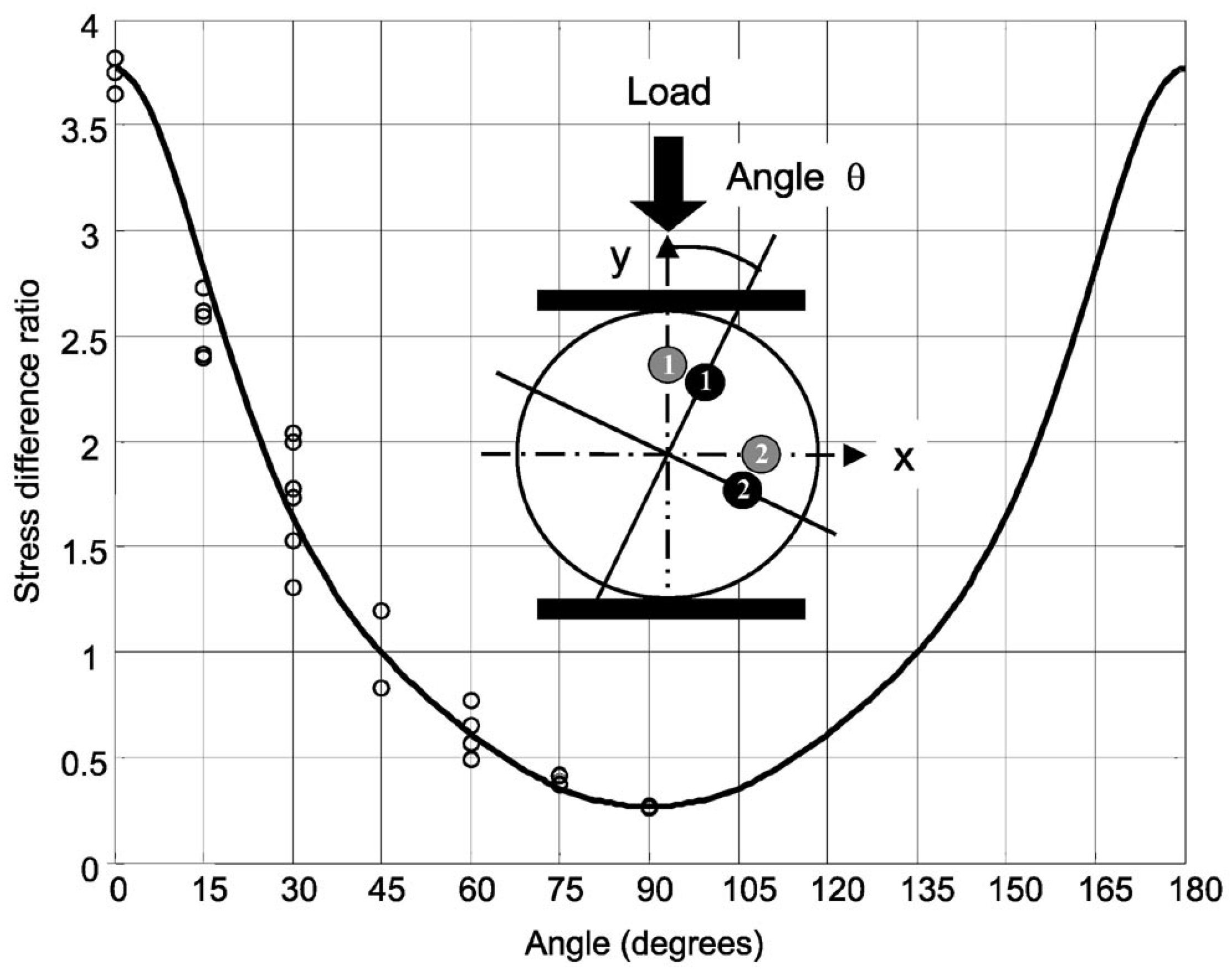
- Silva-Lopez, M.; Li, C.; MacPherson, W.N.; Moore, A.J.; Barton, J.S.; Jones, J.D.; Zhao, D.; Zhang, L.; Bennion, I. Differential birefringence in Bragg gratings in multicore fiber under transverse stress. Opt. Lett. 2004, 29, 2225–2227. [Google Scholar] [CrossRef] [Green Version]
- Silva-Lopez, M.; MacPherson, W.N.; Li, C.; Moore, A.J.; Barton, J.S.; Jones, J.D.; Zhao, D.; Zhang, L.; Bennion, I. Transverse load and orientation measurement with multicore fiber Bragg gratings. Appl. Opt. 2005, 44, 6890–6897. [Google Scholar] [CrossRef] [PubMed] [Green Version]
- MacPherson, W.N.; Flockhart, G.M.; Maier, R.R.; Barton, J.S.; Jones, J.D.; Zhao, D.; Zhang, L.; Bennion, I. Pitch and roll sensing using fibre Bragg gratings in multicore fibre. Meas. Sci. Technol. 2014, 15, 1642–1646. [Google Scholar] [CrossRef] [Green Version]
- Fender, A.; Rigg, E.J.; Maier, R.R.; MacPherson, W.N.; Barton, J.S.; Moore, A.J.; Jones, J.D.; Zhao, D.; Zhang, L.; Bennion, I.; et al. Dynamic two-axis curvature measurement using multicore fiber Bragg gratings interrogated by arrayed waveguide gratings. Appl. Opt. 2006, 45, 9041–9048. [Google Scholar] [CrossRef] [Green Version]
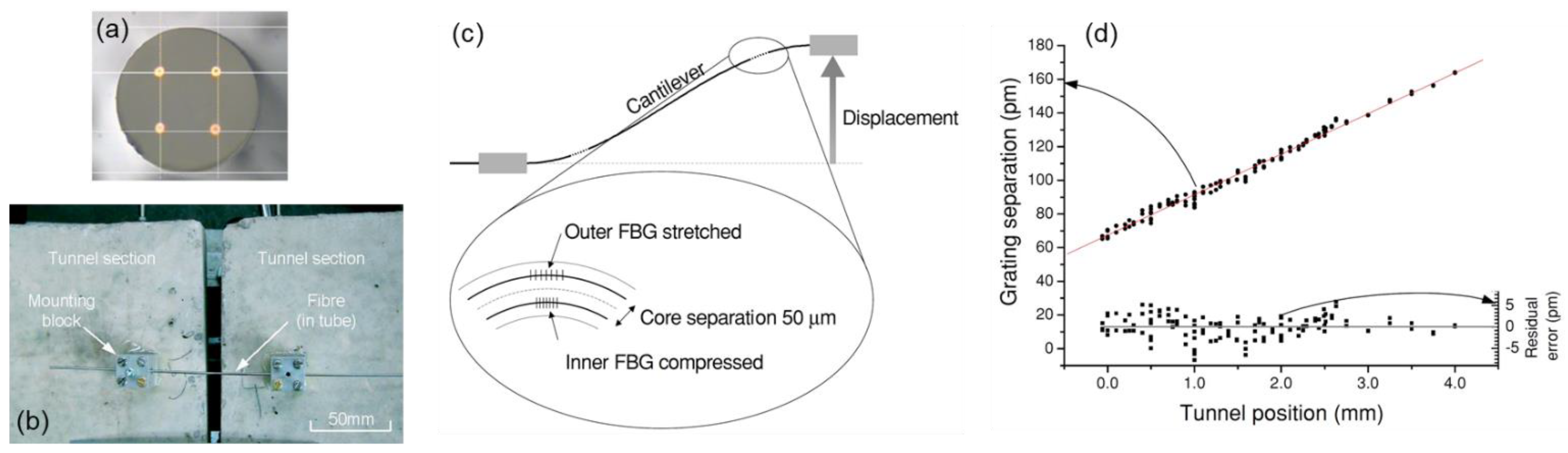
- MacPherson, W.N.; Silva-Lopez, M.; Barton, J.S.; Moore, A.J.; Jones, J.D.C.; Zhao, D.; Zhang, L.; Bennion, I.; Metje, N.; Rogers, C.D.F.; et al. Tunnel monitoring using multicore fiber displacement sensor. Meas. Sci. Technol. 2006, 17, 1180–1185. [Google Scholar] [CrossRef] [Green Version]
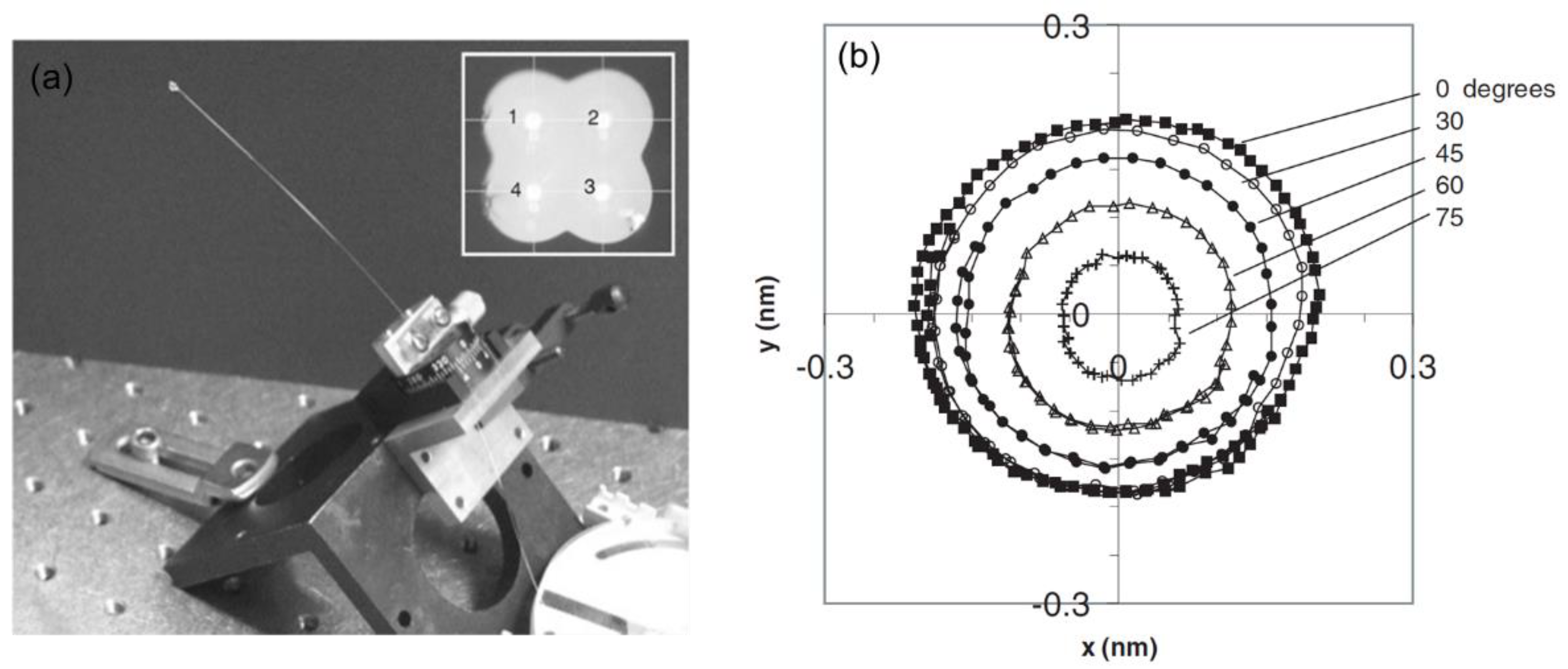
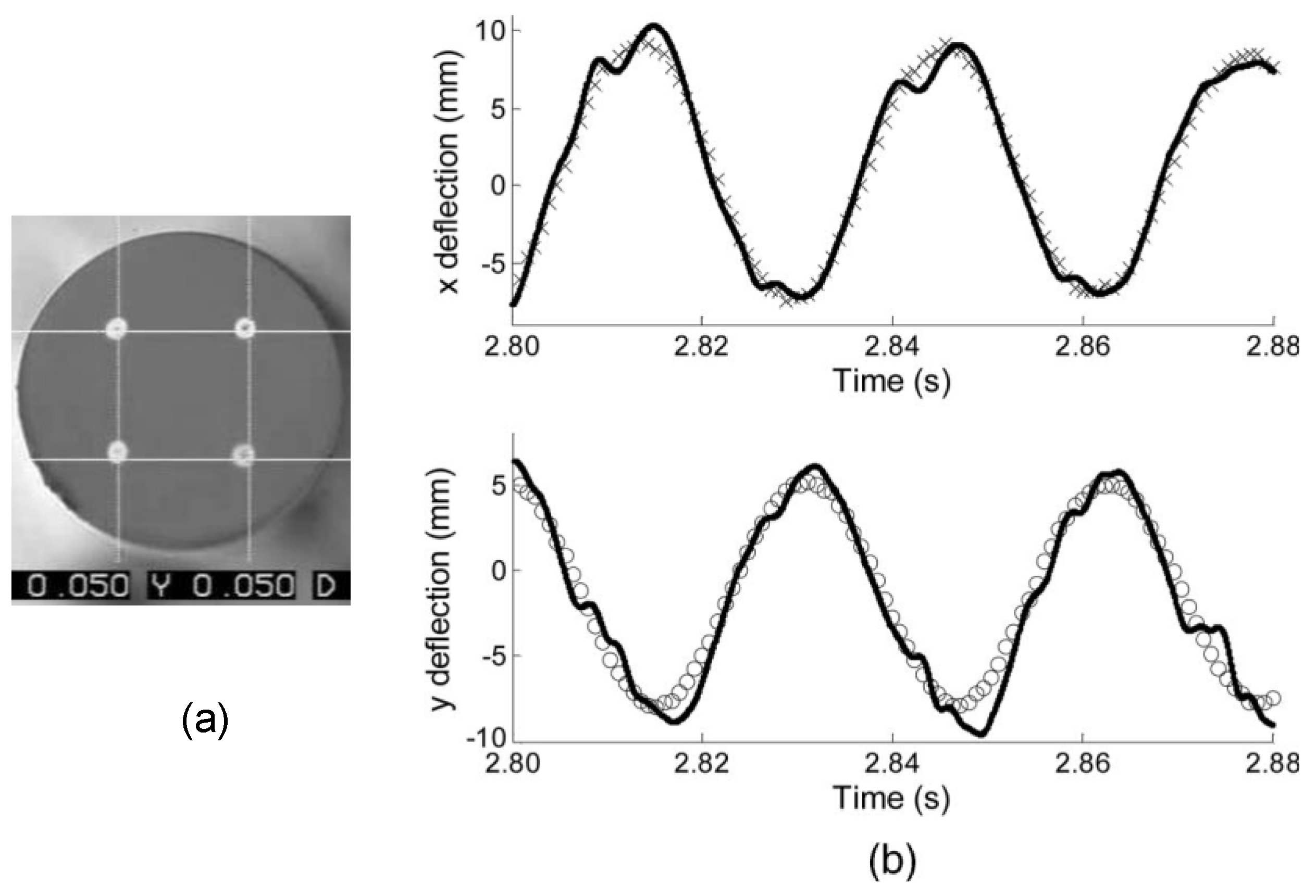
- Fender, A.; MacPherson, W.N.; Maier, R.; Barton, J.S.; George, D.S.; Howden, R.I.; Smith, G.W.; Jones, B.J.; McCulloch, S.; Chen, X.; et al. Two-axis temperature-insensitive accelerometer based on multicore fiber Bragg gratings. IEEE Sens. J. 2008, 8, 1292–1298. [Google Scholar] [CrossRef]
- Fender, A.; MacPherson, W.N.; Maier, R.R.J.; Barton, J.S.; George, D.S.; Howden, R.I.; Smith, G.W.; Jones, B.J.; McCulloch, S.; Chen, X.; et al. Two-axis accelerometer based on multicore fibre Bragg gratings. In Proceedings of the Third European Workshop on Optical Fibre Sensors, Napoli, Italy, 4–6 July 2007; International Society for Optics and Photonics: Bellingham, WA, USA, 2007; Volume 6619, p. 66190Q. [Google Scholar]
- He, X.; Dong, X. Accelerometer Based on the FBG Inscribed in a Twin-Core Fiber. In Proceedings of the Asia Communications and Photonics Conference 2013, Beijing China, 12–15 November 2013; Optical Society of America: Washington, DC, USA, 2013; p. AF2I.16. [Google Scholar]
- Cui, J.; Liu, Z.; Gunawardena, D.S.; Zhao, Z.; Tam, H.Y. Two-dimensional vector accelerometer based on Bragg gratings inscribed in a multi-core fiber. Opt. Express 2019, 27, 20848–20856. [Google Scholar] [CrossRef]
- Zhou, R.; Chen, F.; Li, S.; Wang, R.; Qiao, X. Three-Dimensional Vector Accelerometer Using a Multicore Fiber Inscribed with Three FBGs. J. Lightwave Technol. 2021, 39, 3244–3250. [Google Scholar] [CrossRef]
- Miller, G.A.; Askins, C.G.; Cranch, G.A. Interferometric interrogation of a multicore fiber, two-axis inclinometer. In Proceedings of the 20th International Conference on Optical Fibre Sensors, Edinburgh, UK, 5–9 October 2009; International Society for Optics and Photonics: Bellingham, WA, USA, 2009; Volume 7503, p. 75032R. [Google Scholar]
- Miller, G.A. Fabrication of a multifiber optical inclinometer. IEEE Photon. Technol. Lett. 2015, 27, 1289–1292. [Google Scholar] [CrossRef]
- Flockhart, G.M.H.; Cranch, G.A.; Kirkendall, C.K. Differential phase tracking applied to Bragg gratings in multicore fiber for high-accuracy curvature measurement. In Proceedings of the Smart Structures and Materials 2006: Smart Sensor Monitoring Systems and Applications, San Diego, CA, USA, 27 February–1 March 2006; International Society for Optics and Photonics: Bellingham, WA, USA, 2006; Volume 6167, p. 616701. [Google Scholar]
- Flockhart, G.M.H.; Cranch, G.A.; Kirkendall, C.K. Differential phase tracking applied to Bragg gratings in multi-core fibre for high accuracy curvature measurement. Electron. Lett. 2006, 42, 390–391. [Google Scholar] [CrossRef] [Green Version]
- Askins, C.G.; Miller, G.A.; Friebele, E.J. Bend and twist sensing in a multiple-core optical fiber. In Proceedings of the 2008 Conference on Optical Fiber Communication/National Fiber Optic Engineers Conference, San Diego, CA, USA, 24–28 February 2008; pp. 1–3. [Google Scholar]
- Cui, J.; Gunawardena, D.S.; Liu, Z.; Zhao, Z.; Tam, H.Y. All-fiber two-dimensional inclinometer based on Bragg gratings inscribed in a seven-core multi-core fiber. J. Lightwave Technol. 2020, 38, 2516–2522. [Google Scholar] [CrossRef]
- Amanzadeh, M.; Aminossadati, S.M.; Kizil, M.S.; Rakic, A.D. Recent developments in fibre optic shape sensing. Measurement 2018, 128, 119–137. [Google Scholar] [CrossRef] [Green Version]
- Moore, J.P. Shape sensing using multi-core fiber. In Proceedings of the 2015 Optical Fiber Communications Conference and Exhibition (OFC), Los Angeles, CA, USA, 22–26 March 2015; pp. 1–3. [Google Scholar]
- Duncan, R. Sensing Shape: Fiber-Bragg-Grating Sensor Arrays Monitor Shape at a High Resolution; SPIE Newsroom: Bellingham, WA, USA, 2005. [Google Scholar]
- Soller, B.J.; Gifford, D.K.; Wolfe, M.S.; Froggatt, M.E. High resolution optical frequency domain reflectometry for characterization of components and assemblies. Opt. Express 2005, 13, 666–674. [Google Scholar] [CrossRef] [Green Version]
- Duncan, R.G.; Froggatt, M.E.; Kreger, S.T.; Seeley, R.J.; Gifford, D.K.; Sang, A.K.; Wolfe, M.S. High-accuracy fiber-optic shape sensing. In Proceedings of the Sensor Systems and Networks: Phenomena, Technology, and Applications for NDE and Health Monitoring 2007, San Diego, CA, USA, 19–21 March 2007; International Society for Optics and Photonics: Bellingham, WA, USA, 2007; Volume 6530, p. 65301S. [Google Scholar]
- Froggatt, M.; Moore, J. High spatial resolution distributed strain measurement in optical fiber using Rayleigh scatter. Appl. Opt. 1998, 37, 1735–1740. [Google Scholar] [CrossRef]
- Kreger, S.T.; Gifford, D.K.; Froggatt, M.E.; Soller, B.J.; Wolfe, M.S. High resolution distributed strain or temperature measurements in single-and multi-mode fiber using swept-wavelength interferometry. In Proceedings of the Optical Fiber Sensors 2006, Cancun, Mexico, 23–27 October 2006; Optical Society of America: Washington, DC, USA, 2006; p. ThE42. [Google Scholar]
- Guo, H.; Tang, J.; Li, X.; Zheng, Y.; Yu, H.; Yu, H. On-line writing identical and weak fiber Bragg grating arrays. Chin. Opt. Lett. 2013, 11, 030602. [Google Scholar]
- Westbrook, P.S.; Feder, K.S.; Kremp, T.; Taunay, T.F.; Monberg, E.; Kelliher, J.; Ortiz, R.; Bradley, K.; Abedin, K.S.; Au, D.; et al. Integrated optical fiber shape sensor modules based on twisted multicore fiber grating arrays. In Proceedings of the Optical Fibers and Sensors for Medical Diagnostics and Treatment Applications XIV, San Francisco, CA, USA, 1–2 February 2014; International Society for Optics and Photonics: Bellingham, WA, USA, 2014; Volume 8938, p. 89380H. [Google Scholar]
- Westbrook, S.P.; Kremp, T.; Feder, K.S.; Ko, W.; Monberg, E.M.; Wu, H.; Simoff, D.A.; Ortiz, R.M. Improving distributed sensing with continuous gratings in single and multi-core fibers. In Proceedings of the Optical Fiber Communication Conference 2018, San Diego, CA, USA, 11–15 March 2018; Optical Society of America: Washington, DC, USA, 2018; p. W1K.1. [Google Scholar]
- Floris, I.; Sales, S.; Calderón, P.A.; Adam, J.M. Measurement uncertainty of multicore optical fiber sensors used to sense curvature and bending direction. Measurement 2019, 132, 35–46. [Google Scholar] [CrossRef]
- Khan, F.; Barrera, D.; Sales, S.; Misra, S. Curvature, twist and pose measurements using fiber Bragg gratings in multi-core fiber: A comparative study between helical and straight core fibers. Sens. Actuators A Phys. 2021, 317, 112442. [Google Scholar] [CrossRef]
- Askins, C.G.; Miller, G.A.; Friebele, E.J. Bend and twist sensing in a multi-core optical fiber. In Proceedings of the LEOS 2008-21st Annual Meeting of the IEEE Lasers and Electro-Optics Society, Newport Beach, CA, USA, 9–13 November 2008; pp. 109–110. [Google Scholar]
- Froggatt, M.; Klein, J.; Gifford, D. Shape sensing of multiple core optical fiber. In Proceedings of the Applied Industrial Optics: Spectroscopy, Imaging and Metrology, AIO 2011, Toronto, ON, Canada, 10–14 July 2011; Optical Society of America: Washington, DC, USA, 2011; p. AIMB2. [Google Scholar]
- Lally, E.M.; Reaves, M.; Horrell, E.; Klute, S.; Froggatt, M.E. Fiber optic shape sensing for monitoring of flexible structures. In Proceedings of the Sensors and Smart Structures Technologies for Civil, Mechanical, and Aerospace Systems 2012, San Diego, CA, USA, 12–15 March 2012; International Society for Optics and Photonics: Bellingham, WA, USA, 2012; Volume 8345, p. 83452Y. [Google Scholar]
- Cooper, L.J.; Webb, A.S.; Gillooly, A.; Hill, M.; Read, T.; Maton, P.; Hankey, J.; Bergonzo, A. Design and performance of multicore fiber optimized towards communications and sensing applications. In Proceedings of the Optical Components and Materials XII, San Francisco, CA, USA, 9–11 February 2015; International Society for Optics and Photonics: Bellingham, WA, USA, 2015; Volume 9359, p. 93590H. [Google Scholar]
- Westbrook, P.S.; Feder, K.S.; Kremp, T.; Taunay, T.F.; Monberg, E.; Ortiz, R.; Puc, G. Improved uniformity of sensor gratings in offset core fibers with fiber lensing mitigation. In Proceedings of the Optical Fibers and Sensors for Medical Diagnostics and Treatment Applications XVI, San Francisco, CA, USA, 13–14 February 2016; International Society for Optics and Photonics: Bellingham, WA, USA, 2016; Volume 9702, p. 97020J. [Google Scholar]
- Westbrook, P.S.; Kremp, T.; Feder, K.S.; Ko, W.; Monberg, E.M.; Wu, H.; Simoff, D.A.; Taunay, T.T.; Ortiz, R.M. Continuous multicore optical fiber grating arrays for distributed sensing applications. J. Lightw. Technol. 2017, 35, 1248–1252. [Google Scholar] [CrossRef]
- Floris, I.; Calderón, P.A.; Sales, S.; Adam, J.M. Effects of core position uncertainty on optical shape sensor accuracy. Measurement 2019, 139, 21–33. [Google Scholar] [CrossRef]
- Pauer, H.; Ledermann, C.; Tuschmann, W.; Woern, H. Non-linear compensation of production inaccuracies and material drift by adjusting the sensor data fusion algorithms for shape sensing based on FBG-optical fibers. In Proceedings of the 2014 International Conference on Multisensor Fusion and Information Integration for Intelligent Systems (MFI), Beijing, China, 28–29 September 2014; pp. 1–5. [Google Scholar]
- Floris, I.; Madrigal, J.; Sales, S.; Adam, J.M.; Calderón, P.A. Experimental study of the influence of FBG length on optical shape sensor performance. Opt. Lasers Eng. 2020, 126, 105878. [Google Scholar] [CrossRef]
- Idrisov, R.; Floris, I.; Rothhardt, M.; Bartelt, H. Characterization and calibration of shape sensors based on multicore optical fibre. Opt. Fiber Technol. 2021, 61, 102319. [Google Scholar] [CrossRef]
- Barrera, D.; Gasulla, I.; Sales, S. Multipoint two-dimensional curvature optical fiber sensor based on a nontwisted homogeneous fourcore. J. Lightw. Technol. 2015, 33, 2445–2450. [Google Scholar] [CrossRef]
- Sonoda, N.; Takagi, R.; Saito, I.; Abe, T.; Zhao, S.; Tanaka, Y. Multipoint bending measurement using multicore fiber Bragg grating and two-photon absorption process in Si-APD. IEEE Sens. J. 2021, 21, 25736–25742. [Google Scholar] [CrossRef]
- Moon, H.; Jeong, J.; Kang, S.; Kim, K.; Song, Y.-W.; Kim, J. Fiber Bragg-grating-based ultrathin shape sensors displaying single-channel sweeping for minimally invasive surgery. Opt. Lasers Eng. 2014, 59, 50–55. [Google Scholar] [CrossRef]
- Khan, F.; Denasi, A.; Barrera, D.; Madrigal, J.; Sales, S.; Misra, S. Multi-core optical fibers with Bragg gratings as shape sensor for flexible medical instruments. IEEE Sens. J. 2019, 19, 5878–5884. [Google Scholar] [CrossRef] [Green Version]
- Khan, F.; Donder, A.; Galvan, S.; Baena, F.R.; Misra, S. Pose measurement of flexible medical instruments using fiber bragg gratings in multi-core fiber. IEEE Sens. J. 2020, 20, 10955–10962. [Google Scholar] [CrossRef]
- Al-Ahmad, O.; Ourak, M.; Van Roosbroeck, J.; Vlekken, J.; Vander Poorten, E. Improved fbg-based shape sensing methods for vascular catheterization treatment. IEEE Robot. Autom. Lett. 2020, 5, 4687–4694. [Google Scholar] [CrossRef]
- Lindleyet, E.; Min, S.S.; Leon-Saval, S.; Cvetojevic, N.; Lawrence, J.; Ellis, S.; Bland-Hawthorn, J. Demonstration of uniform multicore fiber Bragg gratings. Opt. Express 2014, 22, 31575–31581. [Google Scholar] [CrossRef]
- Stępień, K.; Slowikowski, M.; Tenderenda, T.; Murawski, M.; Szymanski, M.; Szostkiewicz, L.; Becker, M.; Rothhardt, M.; Bartelt, H.; Mergo, P.; et al. Fiber Bragg gratings in hole-assisted multicore fiber for space division multiplexing. Opt. Lett. 2014, 39, 3571–3574. [Google Scholar] [CrossRef] [PubMed]
- Ishihara, H.; Uemura, H.; Sasaki, Y.; Omichi, K.; Fujisawa, T.; Saitoh, K. Grating inscription to few-mode multi-core optical fiber. In Proceedings of the Asia-Pacific Optical Sensors Conference 2016, Shanghai, China, 11–14 October 2016; Optical Society of America: Washington, DC, USA, 2016; p. Th4A.13. [Google Scholar]
- Idrisov, R.; Becker, M.; Rothhardt, M.; Bierlich, J.; Bartelt, H. Optimisation of fibre Bragg gratings inscription in multicore fibres. In Proceedings of the Optical Fiber Sensors 2018, Lausanne, Switzerland, 24–28 September 2018; Optical Society of America: Washington, DC, USA, 2018; p. WF64. [Google Scholar]
- Donko, A.; Beresna, M.; Jung, Y.; Hayes, J.; Richardson, D.J.; Brambilla, G. Point-by-point femtosecond laser micro-processing of independent core-specific fiber Bragg gratings in a multi-core fiber. Opt. Express 2018, 26, 2039–2044. [Google Scholar] [CrossRef] [PubMed]
- Lee, K.K.C.; Mariampillai, A.; Haque, M.; Standish, B.A.; Yang, V.X.; Herman, P.R. Temperature-compensated fiber-optic 3D shape sensor based on femtosecond laser direct-written Bragg grating waveguides. Opt. Express 2013, 21, 24076–24086. [Google Scholar] [CrossRef]
- Wolf, A.; Dostovalov, A.; Bronnikov, K.; Babin, S. Arrays of fiber Bragg gratings selectively inscribed in different cores of 7-core spun optical fiber by IR femtosecond laser pulses. Opt. Express 2019, 27, 13978–13990. [Google Scholar] [CrossRef]
- Jantzen, S.L.; Bannerman, R.H.S.; Jantzen, A.; Mennea, P.L.; Smith, D.H.; Gates, J.C.; Boyd, L.J.; Smith, P.G.R.; Holmes, C. Individual inscription of spectrally multiplexed Bragg gratings in optical multicore fibers using small spot direct UV writing. Opt. Express 2020, 28, 21300–21309. [Google Scholar] [CrossRef]
- Suo, R.; Lousteau, J.; Li, H.; Jiang, X.; Zhou, K.; Zhang, L.; MacPherson, W.N.; Bookey, H.T.; Barton, J.S.; Kar, A.K.; et al. Fiber Bragg gratings inscribed using 800 nm femtosecond laser and a phase mask in single and multi-core mid-IR glass fibers. Opt. Express 2009, 17, 7540–7548. [Google Scholar] [CrossRef] [PubMed] [Green Version]
- Zhang, Y.; Zhang, W.; Zhang, Y.; Wang, S.; Yu, L.; Yan, Y. Simultaneous measurement of curvature and temperature based on LP11 mode Bragg grating in seven-core fiber. Meas. Sci. Technol. 2017, 28, 055101. [Google Scholar] [CrossRef]
- Kilic, S.G.; Zhu, Y.; Sheng, Q.; Inci, M.N.; Han, M. Refractometer with etched chirped fiber Bragg grating Fabry–Perot interferometer in multicore fiber. IEEE Photon. Technol. Lett. 2019, 31, 575–578. [Google Scholar] [CrossRef]
- Hu, W.; Li, C.; Cheng, S.; Mumtaz, F.; Du, C.; Yang, M. Etched multicore fiber Bragg gratings for refractive index sensing with temperature in-line compensation. OSA Contin. 2020, 3, 1058–1067. [Google Scholar] [CrossRef]
- Zheng, D.; Madrigal, J.; Chen, H.; Barrera, D.; Sales, S. Multicore fiber-Bragg-grating-based directional curvature sensor interrogated by a broadband source with a sinusoidal spectrum. Opt. Lett. 2017, 42, 3710–3713. [Google Scholar] [CrossRef]
- Zheng, D.; Madrigal, J.; Barrera, D.; Sales, S.; Capmany, J. Microwave photonic filtering for interrogating FBG-based multicore fiber curvature sensor. IEEE Photon. Technol. Lett. 2017, 29, 1707–1710. [Google Scholar] [CrossRef]
- Araújo, F.M.; Ferreira, L.A.; Santos, J.L. Simultaneous determination of curvature, plane of curvature and temperature by use of a miniaturized sensing head based on fibre Bragg gratings. Appl. Opt. 2002, 41, 2401–2407. [Google Scholar] [CrossRef] [PubMed]
- Wolf, B.J.; Morton, J.A.S.; MacPherson, W.B.N.; van Netten, S.M. Bio-inspired all -optical artificial neuromast for 2D flow sensing. Bioinspir. Biomim. 2018, 13, 026013. [Google Scholar] [CrossRef] [PubMed]
- Barrera, D.; Madrigal, J.; Sales, S. Tilted fiber Bragg gratings in multicore optical fibers for optical sensing. Opt. Lett. 2017, 42, 1460–1463. [Google Scholar] [CrossRef] [PubMed]
- Madrigal, J.; Barrera, D.; Sales, S. Refractive index and temperature sensor based on TFBGs in multicore fiber. In Proceedings of the Optical Fiber Sensors 2018, Lausanne, Switzerland, 24–28 September 2018; Optical Society of America: Washington, DC, USA, 2018; p. ThE11. [Google Scholar]
- Ortega-Gomez, A.; Loyez, M.; Lobry, M.; Chah, K.; Zubia, J.; Villatoro, J.; Caucheteur, C. Plasmonic sensors based on tilted Bragg gratings in multicore optical fibers. Opt. Express 2021, 29, 18469–18480. [Google Scholar] [CrossRef] [PubMed]
- Saffari, P.; Allsop, T.; Adebayo, A.; Webb, D.; Haynes, R.; Roth, M.M. Long period grating in multicore optical fiber: An ultra-sensitive vector bending sensor for low curvatures. Opt. Lett. 2014, 39, 3508–3511. [Google Scholar] [CrossRef] [Green Version]
- Barrera, D.; Madrigal, J.; Sales, S. Long period gratings in multicore optical fibers for directional curvature sensor implementation. J. Lightw. Technol. 2018, 36, 1063–1068. [Google Scholar] [CrossRef]
- Wang, S.; Zhang, W.; Chen, L.; Zhang, Y.; Geng, P.; Zhang, Y.; Yan, T.; Yu, L.; Hu, W.; Li, Y. Two-dimensional microbend sensor based on long period fiber gratings in an isosceles triangle arrangement three-core fiber. Opt. Lett. 2017, 42, 4938–4941. [Google Scholar] [CrossRef]
- Barrera, S.; Goicoechea, J.; Madrigal, J.; González-Larequi, M.; Arregui, F.J.; Sales, S. Partially coated long period fiber Bragg gratings in multicore optical fibers. In Proceedings of the Optical Sensors 2018, Zurich, Switzerland, 2–5 July 2018; Optical Society of America: Washington, DC, USA, 2018; p. SeM4E.5. [Google Scholar]
- Wang, R.; Tang, M.; Fu, S.; Feng, Z.; Tong, W.; Liu, D. Spatially arrayed long period gratings in multicore fiber by programmable electrical arc discharge. IEEE Photon. J. 2017, 9, 1–10. [Google Scholar] [CrossRef]
- Szostkiewicz, Ł.; Soto, M.A.; Yang, Z.; Dominguez-Lopez, A.; Parola, I.; Markiewicz, K.; Pytel, A.; Kołakowska, A.; Napierała, M.; Nasiłowski, T.; et al. High-resolution distributed shape sensing using phase-sensitive optical time-domain reflectometry and multicore fiber. Opt. Express 2019, 27, 20763–20773. [Google Scholar] [CrossRef]
- Wang, Q.; Liu, Y. Review of optical fiber bending/curvature sensor. Measurement 2018, 130, 161–176. [Google Scholar] [CrossRef]


| Type of Sensor | Application | Principle/Feature | Refs. |
|---|---|---|---|
| MCF-based FBG sensor | Bending/curvature sensing | Fiber bending causes differential response in different cores | [37,38,39,41,42,43,82,83,100,101] |
| Transverse loading sensing | Transverse stress causes birefringence change | [44,45] | |
| Vibration sensing | Fiber bending causes output power change of FBGs | [47] | |
| Displacement sensing | Displacement causes fiber curvature change | [48] | |
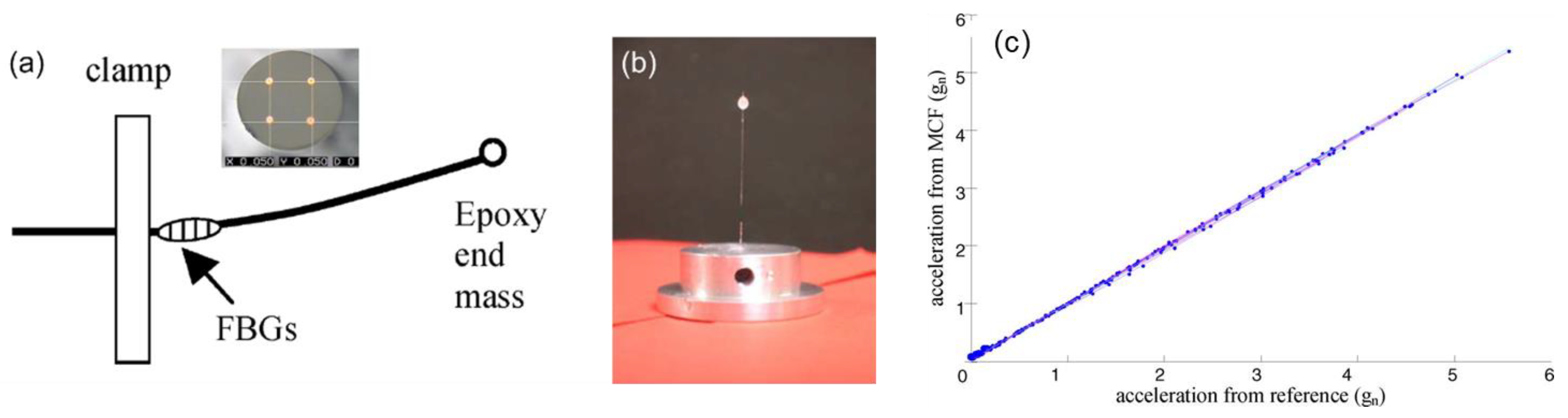
| Acceleration sensing | Fiber bending causes differential strain in different cores | [49,50,51,52,53] | |
| Inclinometer sensor | Fiber bending causes differential strain in different cores | [54,55,59] | |
| 3-D shape sensing | Differential strain in different cores | [35,60,61,62,64,68,71,73,74,77,78,79,80,81,84,85,86,87] | |
| Temperature, strain sensing | Temperature and strain sensitivity | [96,97] | |
| Refractive index sensing | Using etched multicore fiber | [98,99] | |
| MCF-based TFBG sensor | Temperature, curvature and refractive index sensing | Inter-core crosstalk, surface plasmon resonance | [104,105,106] |
| MCF-based LPG sensor | Bending sensing | Fiber bending causes wavelength shift of LPGs | [107,108,109] |
| Refractive index sensing | Fiber surface is partially coated with a thin film SnO2 layer | [110] | |
| Temperature, strain sensing | Temperature and strain sensitivity | [111] | |
| MCF-based distributed fiber sensor | Curvature and 3-D shape sensing | Measuring the differential strain using BOTDA technique | [24] |
| Temperature and strain discriminative sensing | Hybrid Raman and Brillouin sensor, or using heterogeneous multicore fiber | [25,26] | |
| High performance distributed fiber sensing | Large dynamic range and ultra-high measurement resolution simultaneously | [27] | |
| Multi-parameter sensing | Using a hybrid sensing system, e.g., DTS and DAS, simultaneously | [28,29] | |
| Distributed vibration sensing | MCF interferometer enables wide frequency measurement range | [30,31] |
Publisher’s Note: MDPI stays neutral with regard to jurisdictional claims in published maps and institutional affiliations. |
© 2022 by the authors. Licensee MDPI, Basel, Switzerland. This article is an open access article distributed under the terms and conditions of the Creative Commons Attribution (CC BY) license (https://creativecommons.org/licenses/by/4.0/).
Share and Cite
Zhao, Z.; Dang, Y.; Tang, M. Advances in Multicore Fiber Grating Sensors. Photonics 2022, 9, 381. https://doi.org/10.3390/photonics9060381
Zhao Z, Dang Y, Tang M. Advances in Multicore Fiber Grating Sensors. Photonics. 2022; 9(6):381. https://doi.org/10.3390/photonics9060381
Chicago/Turabian StyleZhao, Zhiyong, Yunli Dang, and Ming Tang. 2022. "Advances in Multicore Fiber Grating Sensors" Photonics 9, no. 6: 381. https://doi.org/10.3390/photonics9060381