Mode-Conversion-Based Chirped Bragg Gratings on Thin-Film Lithium Niobate

 , ,
, ,
Abstract
:1. Introduction
2. Methods
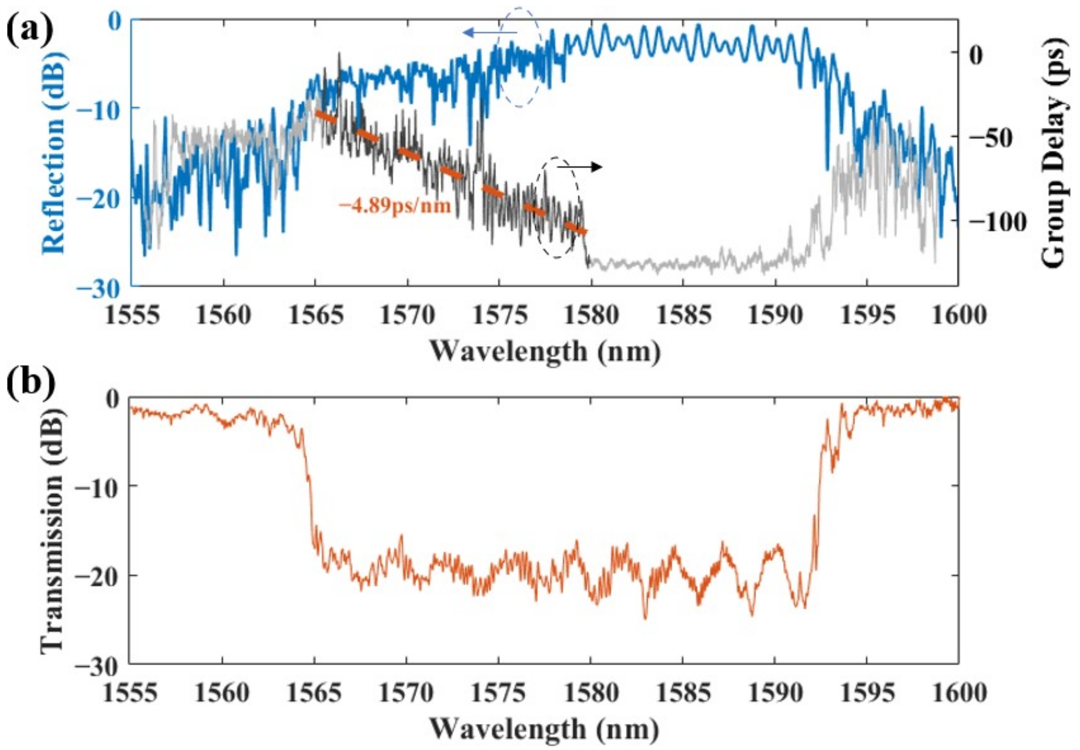
3. Results
4. Discussion and Conclusions
Author Contributions
Funding
Institutional Review Board Statement
Informed Consent Statement
Data Availability Statement
Acknowledgments
Conflicts of Interest
References
- Sumetsky, M.; Eggleton, B. Fiber Bragg gratings for dispersion compensation in optical communication systems. J. Opt. Fiber Commun. Rep. 2005, 2, 256–278. [Google Scholar] [CrossRef]
- Mustafa, F.M.; Zaky, S.A.; Khalaf, A.A.M.; Aly, M.H. A cascaded FBG scheme based OQPSK/DPSK modulation for chromatic dispersion compensation. Opt. Quantum Electron. 2022, 54, 7. [Google Scholar] [CrossRef]
- Min, R.; Korganbayev, S.; Molardi, C.; Broadway, C.; Hu, X.; Caucheteur, C.; Bang, O.; Antunes, P.; Tosi, D.; Marques, C.; et al. Largely tunable dispersion chirped polymer FBG. Opt. Lett. 2018, 43, 5106–5109. [Google Scholar] [CrossRef]
- Min, R.; Ortega, B.; Marques, C. Fabrication of tunable chirped mPOF Bragg gratings using a uniform phase mask. Opt. Express 2018, 26, 4411–4420. [Google Scholar] [CrossRef] [PubMed]
- Chang, H.Y.; Chang, Y.C.; Sheng, H.J.; Fu, M.Y.; Liu, W.F.; Kashyap, R. An Ultra-Sensitive Liquid-Level Indicator Based on an Etched Chirped-Fiber Bragg Grating. IEEE Photonics Technol. Lett. 2016, 28, 268–271. [Google Scholar] [CrossRef]
- Tosi, D.; Macchi, E.G.; Gallati, M.; Braschi, G.; Cigada, A.; Rossi, S.; Leen, G.; Lewis, E. Fiber-optic chirped FBG for distributed thermal monitoring of ex-vivo radiofrequency ablation of liver. Biomed. Opt. Express 2014, 5, 1799–1811. [Google Scholar] [CrossRef] [Green Version]
- Zhou, W.; Dong, X.; Ni, K.; Chan, C.; Shum, P. Temperature-insensitive accelerometer based on a strain-chirped FBG. Sens. Actuators A Phys. 2010, 157, 15–18. [Google Scholar] [CrossRef]
- He, X.; bo Liu, Z.; Wang, D.N. Wavelength-tunable, passively mode-locked fiber laser based on graphene and chirped fiber Bragg grating. Opt. Lett. 2012, 37, 2394–2396. [Google Scholar] [CrossRef] [Green Version]
- Li, S.; Chan, T. Electrical wavelength-tunable actively mode-locked fiber ring laser with a linearly chirped fiber Bragg grating. IEEE Photonics Technol. Lett. 1998, 10, 799–801. [Google Scholar] [CrossRef]
- Tang, Z.; Pan, S.; Zhu, D.; Guo, R.; Zhao, Y.; Pan, M.; Ben, D.; Yao, J. Tunable Optoelectronic Oscillator Based on a Polarization Modulator and a Chirped FBG. IEEE Photonics Technol. Lett. 2012, 24, 1487–1489. [Google Scholar] [CrossRef]
- Wang, C.; Yao, J. A Nonuniformly Spaced Microwave Photonic Filter Using a Spatially Discrete Chirped FBG. IEEE Photonics Technol. Lett. 2013, 25, 1889–1892. [Google Scholar] [CrossRef]
- Burla, M.; Cortés, L.R.; Li, M.; Wang, X.; Chrostowski, L.; Azaña, J. Integrated waveguide Bragg gratings for microwave photonics signal processing. Opt. Express 2013, 21, 25120–25147. [Google Scholar] [CrossRef] [PubMed] [Green Version]
- Kaushal, S.; Cheng, R.; Ma, M.; Mistry, A.; Burla, M.; Chrostowski, L.; Azaña, J. Optical signal processing based on silicon photonics waveguide Bragg gratings. Front. Optoelectron. 2018, 11, 163–188. [Google Scholar] [CrossRef]
- Cheng, R.; Chrostowski, L. Spectral design of silicon integrated Bragg gratings: A tutorial. J. Light. Technol. 2020, 39, 712–729. [Google Scholar] [CrossRef]
- Liu, Y.; Huang, X.; Guan, H.; Yu, Z.; Wei, Q.; Fan, Z.; Han, W.; Li, Z. C-band four-channel CWDM (de-) multiplexers on a thin film lithium niobate–silicon rich nitride hybrid platform. Opt. Lett. 2021, 46, 4726–4729. [Google Scholar] [CrossRef] [PubMed]
- Strain, M.J.; Sorel, M. Design and fabrication of integrated chirped Bragg gratings for on-chip dispersion control. IEEE J. Quantum Electron. 2010, 46, 774–782. [Google Scholar] [CrossRef]
- Giuntoni, I.; Stolarek, D.; Bruns, J.; Zimmermann, L.; Tillack, B.; Petermann, K. Integrated dispersion compensator based on apodized SOI Bragg gratings. IEEE Photonics Technol. Lett. 2013, 25, 1313–1316. [Google Scholar] [CrossRef]
- Sun, H.; Wang, Y.; Chen, L.R. Integrated discretely tunable optical delay line based on step-chirped subwavelength grating waveguide Bragg gratings. J. Light. Technol. 2020, 38, 5551–5560. [Google Scholar] [CrossRef]
- Chen, L.R. Photonic generation of chirped microwave and millimeter wave pulses based on optical spectral shaping and wavelength-to-time mapping in silicon photonics. Opt. Commun. 2016, 373, 70–81. [Google Scholar] [CrossRef]
- Yu, M.; Reimer, C.; Barton, D.; Kharel, P.; Cheng, R.; He, L.; Shao, L.; Zhu, D.; Hu, Y.; Grant, H.R.; et al. Femtosecond pulse generation via an integrated electro-optic time lens. arXiv 2021. [Google Scholar] [CrossRef]
- Du, Z.; Xiang, C.; Fu, T.; Chen, M.; Yang, S.; Bowers, J.E.; Chen, H. Silicon nitride chirped spiral Bragg grating with large group delay. APL Photonics 2020, 5, 101302. [Google Scholar] [CrossRef]
- Chen, Z.; Flueckiger, J.; Wang, X.; Zhang, F.; Yun, H.; Lu, Z.; Caverley, M.; Wang, Y.; Jaeger, N.A.; Chrostowski, L. Spiral Bragg grating waveguides for TM mode silicon photonics. Opt. Express 2015, 23, 25295–25307. [Google Scholar] [CrossRef] [PubMed]
- Sun, Y.; Wang, D.; Deng, C.; Lu, M.; Huang, L.; Hu, G.; Yun, B.; Zhang, R.; Li, M.; Dong, J.; et al. Large Group Delay in Silicon-on-Insulator Chirped Spiral Bragg Grating Waveguide. IEEE Photonics J. 2021, 13, 5500205. [Google Scholar] [CrossRef]
- Ma, M.; Chen, Z.; Yun, H.; Wang, Y.; Wang, X.; Jaeger, N.A.; Chrostowski, L. Apodized spiral Bragg grating waveguides in silicon-on-insulator. IEEE Photonics Technol. Lett. 2017, 30, 111–114. [Google Scholar] [CrossRef]
- Giuntoni, I.; Stolarek, D.; Kroushkov, D.I.; Bruns, J.; Zimmermann, L.; Tillack, B.; Petermann, K. Continuously tunable delay line based on SOI tapered Bragg gratings. Opt. Express 2012, 20, 11241–11246. [Google Scholar] [CrossRef]
- Giuntoni, I.; Stolarek, D.; Gajda, A.; Winzer, G.; Bruns, J.; Tillack, B.; Petermann, K.; Zimmermann, L. Integrated drop-filter for dispersion compensation based on SOI rib waveguides. In Proceedings of the Optical Fiber Communication Conference 2010, San Diego, CA, USA, 21–25 March 2010; p. OThJ5. [Google Scholar] [CrossRef]
- Shi, W.; Wang, X.; Lin, C.; Yun, H.; Liu, Y.; Baehr-Jones, T.; Hochberg, M.; Jaeger, N.A.; Chrostowski, L. Silicon photonic grating-assisted, contra-directional couplers. Opt. Express 2013, 21, 3633–3650. [Google Scholar] [CrossRef]
- Simard, A.D.; LaRochelle, S. Complex apodized Bragg grating filters without circulators in silicon-on-insulator. Opt. Express 2015, 23, 16662–16675. [Google Scholar] [CrossRef]
- Qiu, H.; Jiang, J.; Yu, P.; Dai, T.; Yang, J.; Yu, H.; Jiang, X. Silicon band-rejection and band-pass filter based on asymmetric Bragg sidewall gratings in a multimode waveguide. Opt. Lett. 2016, 41, 2450–2453. [Google Scholar] [CrossRef]
- Xiao, R.; Shi, Y.; Li, J.; Dai, P.; Ma, C.; Chen, M.; Zhao, Y.; Chen, X. Integrated Bragg grating filter with reflection light dropped via two mode conversions. J. Light. Technol. 2019, 37, 1946–1953. [Google Scholar] [CrossRef]
- Zhu, D.; Shao, L.; Yu, M.; Cheng, R.; Desiatov, B.; Xin, C.; Hu, Y.; Holzgrafe, J.; Ghosh, S.; Shams-Ansari, A.; et al. Integrated photonics on thin-film lithium niobate. Adv. Opt. Photonics 2021, 13, 242–352. [Google Scholar] [CrossRef]
- Wang, C.; Zhang, M.; Chen, X.; Bertrand, M.; Shams-Ansari, A.; Chandrasekhar, S.; Winzer, P.; Lončar, M. Integrated lithium niobate electro-optic modulators operating at CMOS-compatible voltages. Nature 2018, 562, 101–104. [Google Scholar] [CrossRef] [PubMed]
- Huang, X.; Liu, Y.; Tu, D.; Yu, Z.; Wei, Q.; Li, Z. Linearity-Enhanced Dual-Parallel Mach–Zehnder Modulators Based on a Thin-Film Lithium Niobate Platform. Photonics 2022, 9, 197. [Google Scholar] [CrossRef]
- Escalé, M.R.; Pohl, D.; Sergeyev, A.; Grange, R. Extreme electro-optic tuning of Bragg mirrors integrated in lithium niobate nanowaveguides. Opt. Lett. 2018, 43, 1515–1518. [Google Scholar] [CrossRef] [PubMed]


| Drop Function Method | Grating Type | Operation Bandwidth (nm) | Delay Range (ps) | Grating Length (mm) | Platform | Ref. |
|---|---|---|---|---|---|---|
| Y-branch | Spiral chirped | 11.7 | 128.7 | 4 | SOI | [22] |
| Y-branch | Spiral chirped | 8.8 | 31.2 | 3 | SOI | [24] |
| Circulator | Step-chirped | 41.7 | 60 | 4.98 | SOI | [18] |
| Circulator | Spiral chirped | 9.2 | 1440 | 138 | SiN | [21] |
| Circulator | Chirped | 20 | 32 | 2.5 | LNOI | [20] |
| ADC | Chirped | 15 | 73.4 | 4.7 | LNOI | This work |
Publisher’s Note: MDPI stays neutral with regard to jurisdictional claims in published maps and institutional affiliations. |
© 2022 by the authors. Licensee MDPI, Basel, Switzerland. This article is an open access article distributed under the terms and conditions of the Creative Commons Attribution (CC BY) license (https://creativecommons.org/licenses/by/4.0/).
Share and Cite
Tu, D.; Huang, X.; Yin, Y.; Yu, H.; Yu, Z.; Guan, H.; Li, Z. Mode-Conversion-Based Chirped Bragg Gratings on Thin-Film Lithium Niobate. Photonics 2022, 9, 828. https://doi.org/10.3390/photonics9110828
Tu D, Huang X, Yin Y, Yu H, Yu Z, Guan H, Li Z. Mode-Conversion-Based Chirped Bragg Gratings on Thin-Film Lithium Niobate. Photonics. 2022; 9(11):828. https://doi.org/10.3390/photonics9110828
Chicago/Turabian StyleTu, Donghe, Xingrui Huang, Yuxiang Yin, Hang Yu, Zhiguo Yu, Huan Guan, and Zhiyong Li. 2022. "Mode-Conversion-Based Chirped Bragg Gratings on Thin-Film Lithium Niobate" Photonics 9, no. 11: 828. https://doi.org/10.3390/photonics9110828