Two-Dimensional Elliptical Microresonator Arrays for Wide Flat Bandwidth and Boxlike Filter Response

 , ,
, ,
Abstract
:1. Introduction
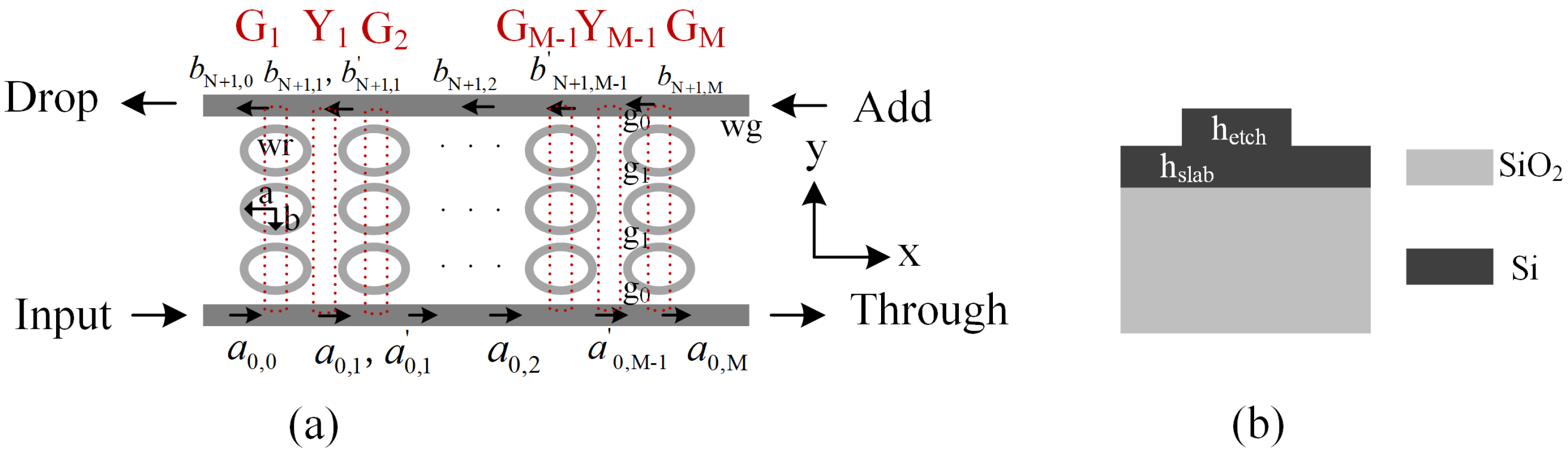
2. Methods
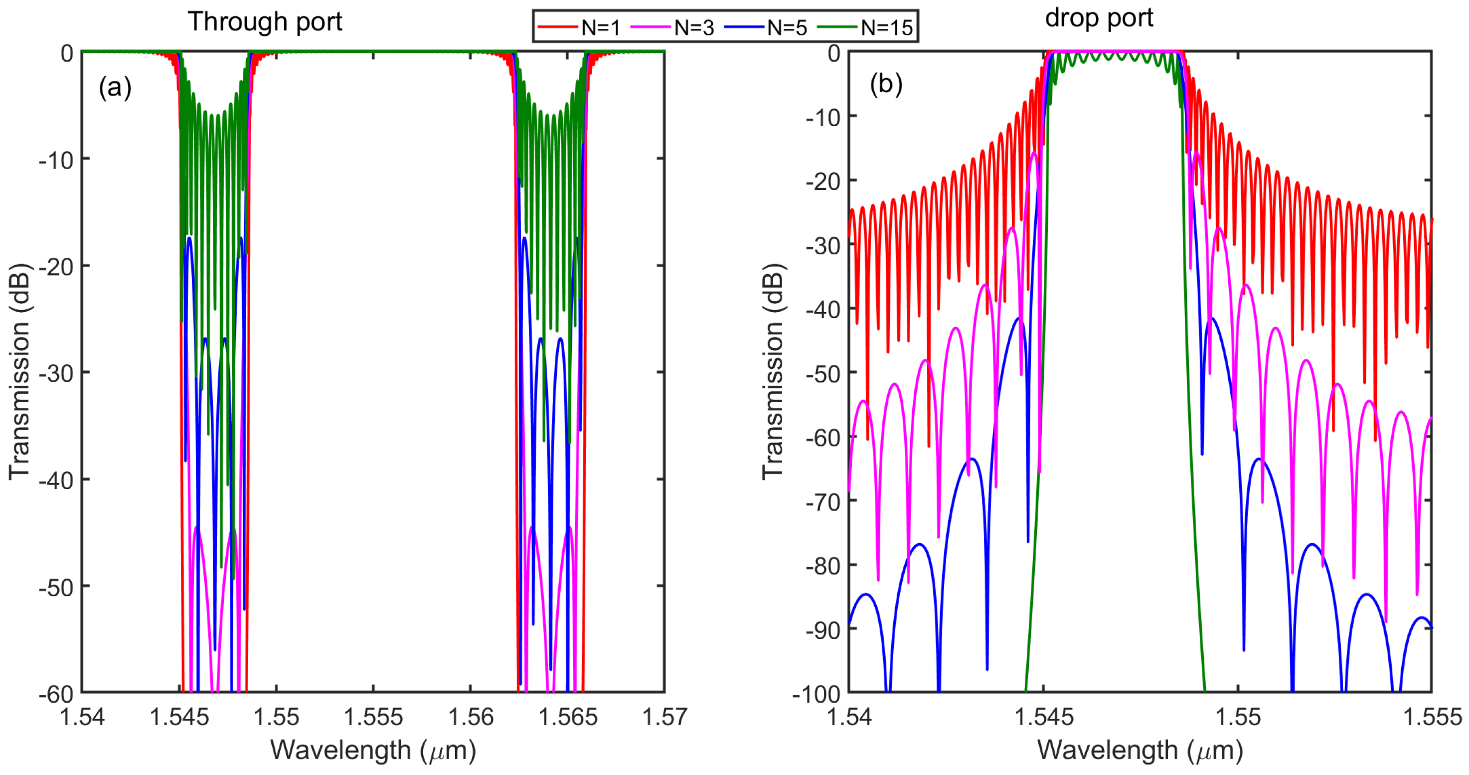
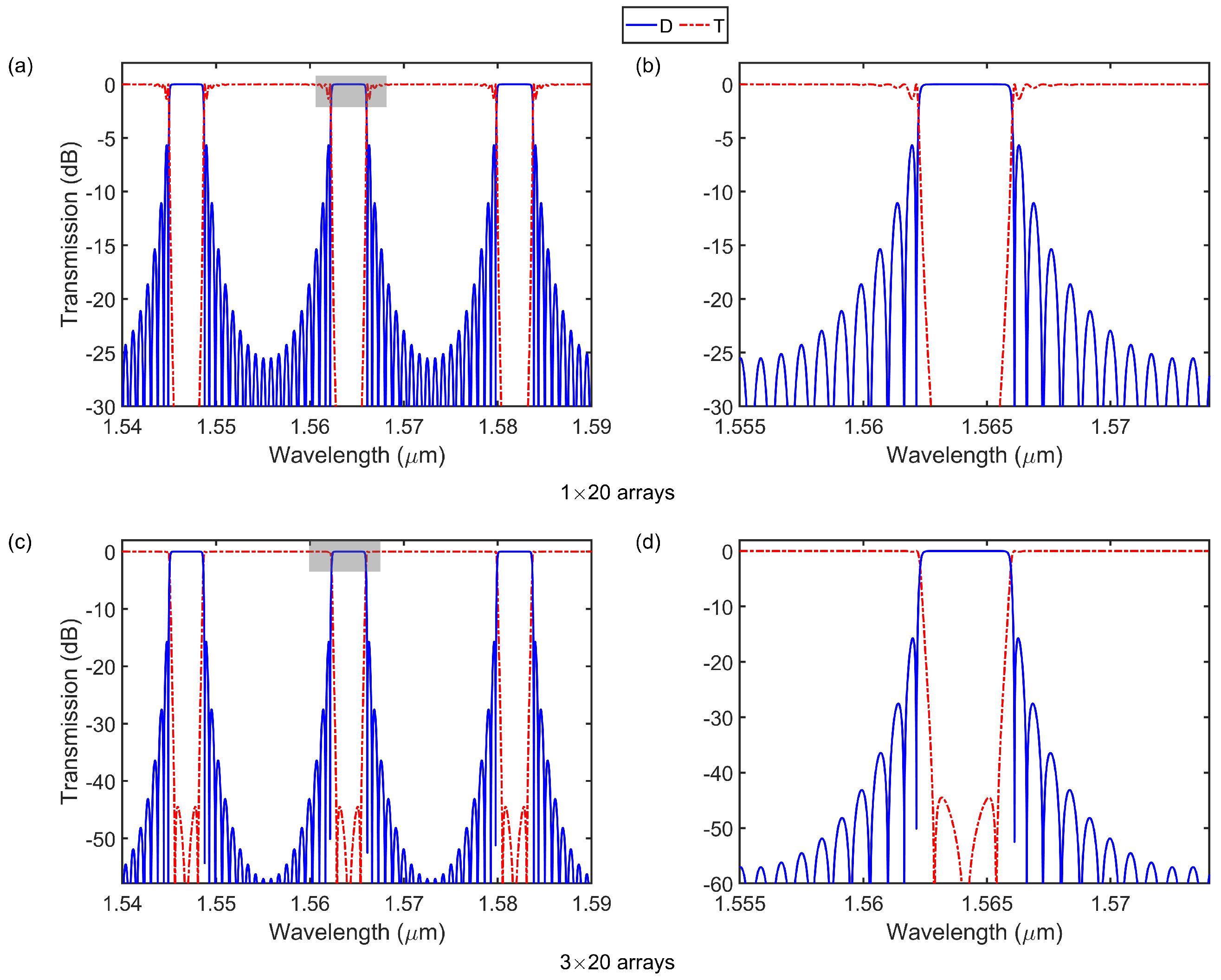
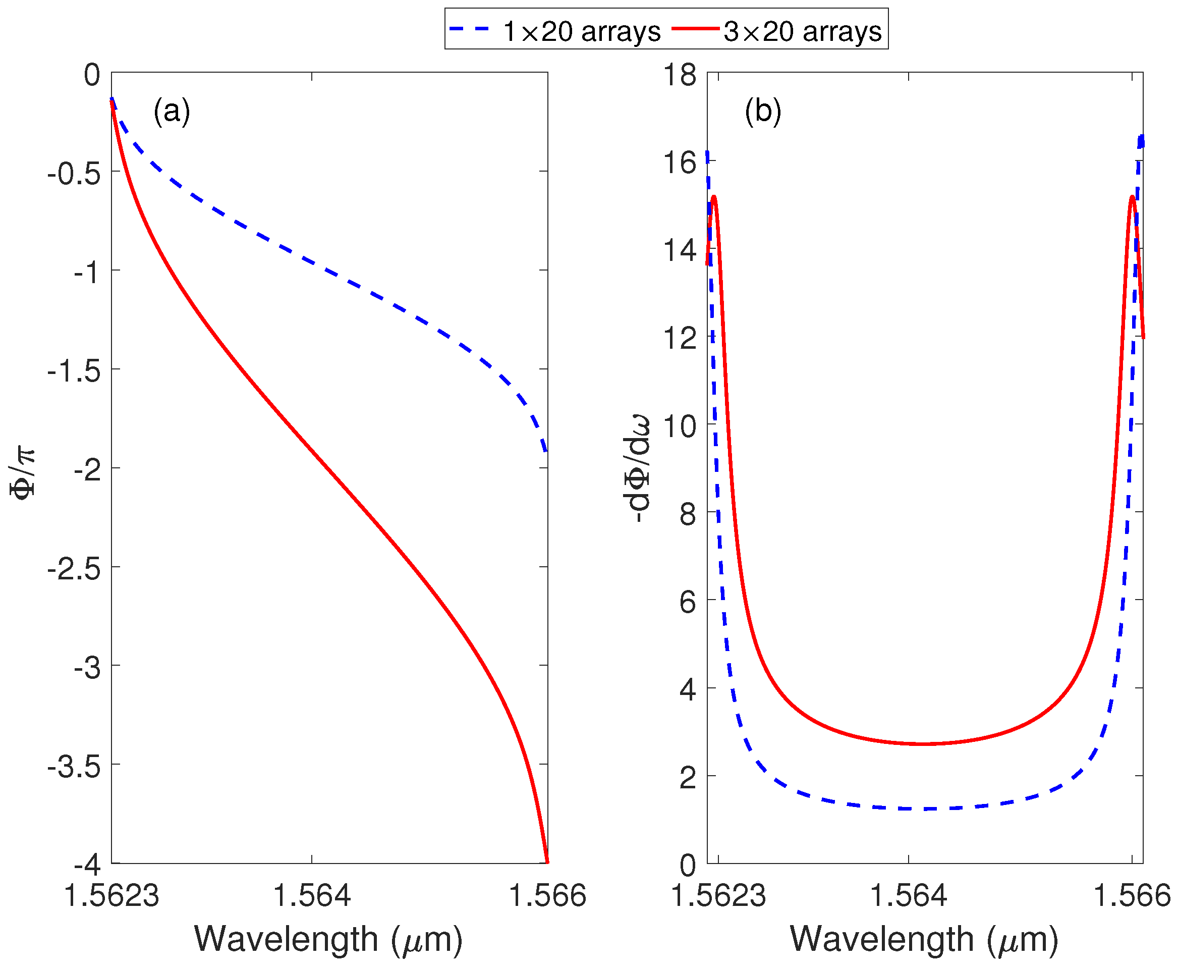
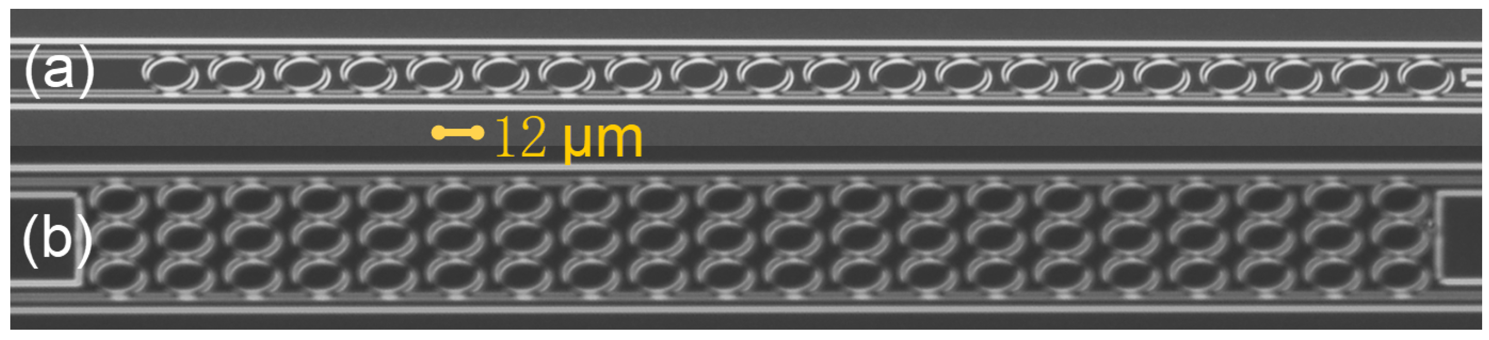
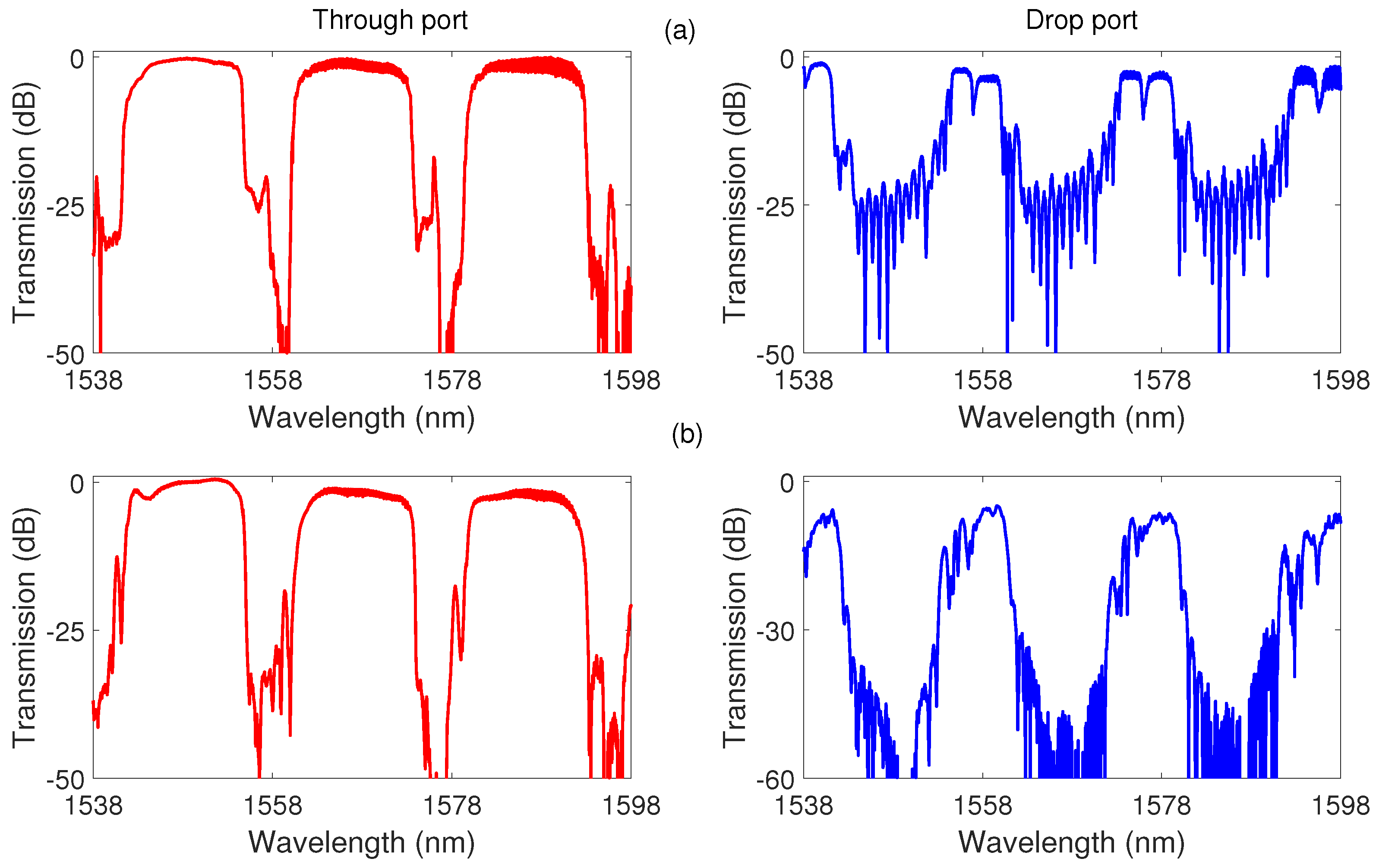
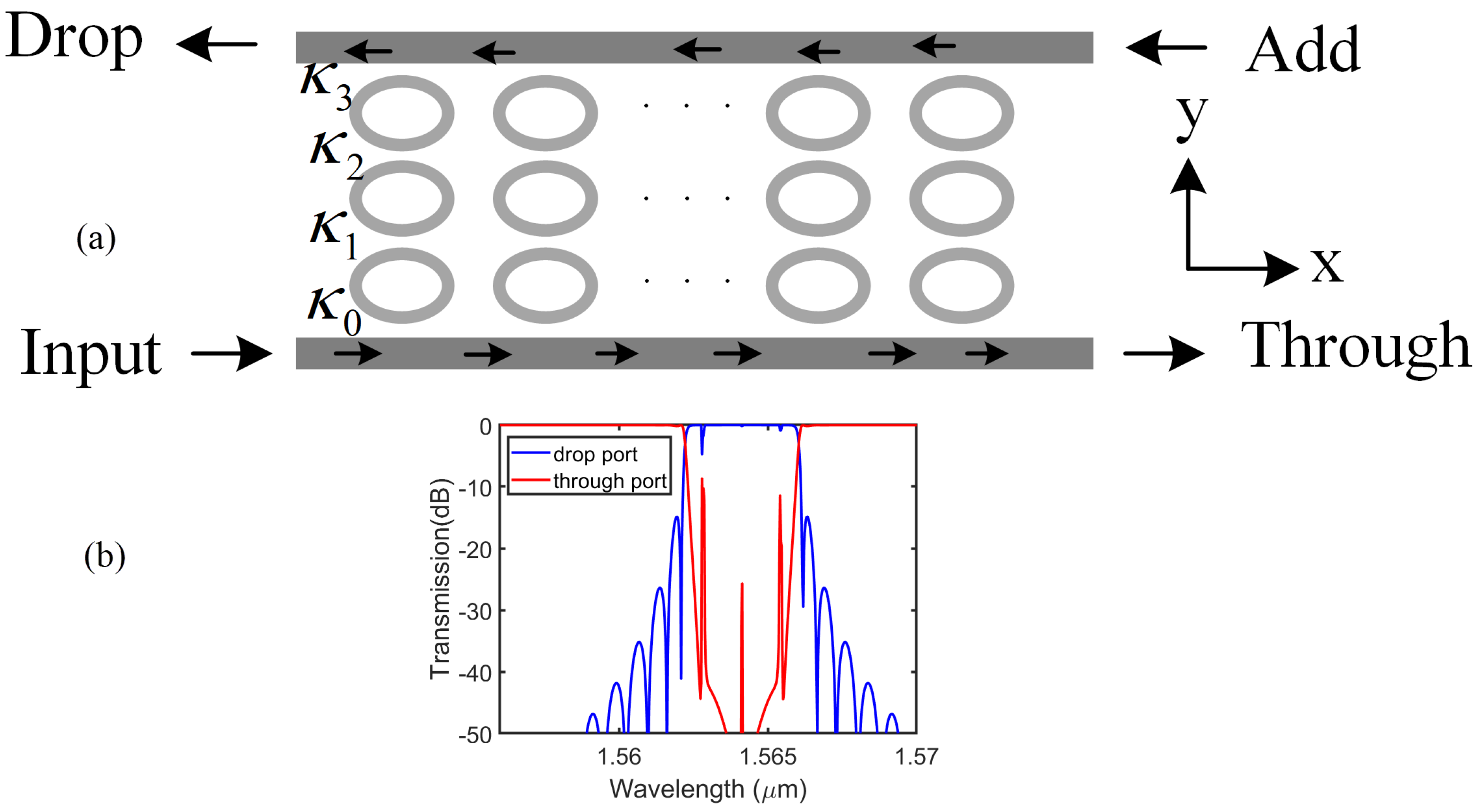
3. Results and Discussion
4. Conclusions
Author Contributions
Funding
Data Availability Statement
Conflicts of Interest
References
- Ren, Y.; Perron, D.; Aurangozeb, F.; Jiang, Z.; Hossain, M.; Van, V. Silicon Photonic Vernier Cascaded Microring Filter for Broadband Tunability. IEEE Photonics Technol. Lett. 2019, 31, 1503–1506. [Google Scholar] [CrossRef]
- Liu, D.; Zhang, C.; Liang, D.; Dai, D. Submicron-resonator-based add-drop optical filter with an ultra-large free spectral range. Opt. Express 2019, 27, 416–422. [Google Scholar] [CrossRef]
- Poulopoulos, G.; Giannoulis, G.; Iliadis, N.; Kalavrouziotis, D.; Apostolopoulos, D.; Avramopoulos, H. Flexible Filtering Element on SOI With Wide Bandwidth Tunability and Full FSR tuning. J. Light. Technol. 2019, 37, 300–306. [Google Scholar] [CrossRef]
- Zhang, Z.; Li, H.; Huang, B.; Zhang, Z.; Cheng, C.; Gao, T.; Yu, Y.; Li, Y.; Chen, H. Multi-channel silicon photonic receiver based on compact second-order microring resonators. Opt. Commun. 2019, 437, 168–173. [Google Scholar] [CrossRef]
- Yang, H.; Li, J.; Zheng, P.; Hu, G.; Yun, B.; Cui, Y. A Stopband and Passband Switchable Microwave Photonic Filter Based on Integrated Dual Ring Coupled Mach-Zehnder Interferometer. IEEE Photonics J. 2019, 11, 5502608. [Google Scholar] [CrossRef]
- Mistry, A.; Hammood, M.; Shoman, H.; Chrostowski, L.; Jaeger, N.A.F. Bandwidth-tunable, FSR-free, microring-based, SOI filter with integrated contra-directional couplers. Opt. Lett. 2018, 43, 6041–6044. [Google Scholar] [CrossRef]
- Ciminelli, C.; Dell’Olio, F.; Brunetti, G.; Conteduca, D.; Armenise, M.N. New microwave photonic filter based on a ring resonator including a photonic crystal structure. In Proceedings of the 2017 19th International Conference on Transparent Optical Networks (ICTON), Girona, Spain, 2–6 July 2017; pp. 1–4. [Google Scholar] [CrossRef]
- Ciminelli, C.; Innone, F.; Brunetti, G.; Conteduca, D.; Dell’Olio, F.; Tatoli, T.; Armenise, M.N. Rigorous model for the design of ultra-high Q-factor resonant cavities. In Proceedings of the 2016 18th International Conference on Transparent Optical Networks (ICTON), Trento, Italy, 10–14 July 2016; pp. 1–4. [Google Scholar] [CrossRef]
- Spencer, D.T.; Bauters, J.F.; Heck, M.J.R.; Bowers, J.E. Integrated waveguide coupled Si3N4 resonators in the ultrahigh-Q regime. Optica 2014, 1, 153–157. [Google Scholar] [CrossRef] [Green Version]
- Brunetti, G.; Dell’Olio, F.; Conteduca, D.; Armenise, M.N.; Ciminelli, C. Ultra-Compact Tuneable Notch Filter Using Silicon Photonic Crystal Ring Resonator. J. Light. Technol. 2019, 37, 2970–2980. [Google Scholar] [CrossRef]
- Kang, Y.M.; Arbabi, A.; Goddard, L.L. Engineering the spectral reflectance of microring resonators with integrated reflective elements. Opt. Express 2010, 18, 16813–16825. [Google Scholar] [CrossRef]
- Shen, L.; Lu, L.; Guo, Z.; Zhou, L.; Chen, J. Silicon optical filters reconfigured from a 16 × 16 Benes switch matrix. Opt. Express 2019, 27, 16945–16957. [Google Scholar] [CrossRef]
- Chew, S.X.; Yi, X.; Song, S.; Li, L.; Bian, P.; Nguyen, L.; Minasian, R.A. Silicon-on-Insulator Dual-Ring Notch Filter for Optical Sideband Suppression and Spectral Characterization. J. Light. Technol. 2016, 34, 4705–4714. [Google Scholar] [CrossRef]
- Grover, R.; Van, V.; Ibrahim, T.; Absil, P.; Calhoun, L.; Johnson, F.; Hryniewicz, J.; Ho, P. Parallel-cascaded semiconductor microring resonators for high-order and wide-FSR filters. J. Light. Technol. 2002, 20, 872–877. [Google Scholar] [CrossRef]
- Capmany, J.; Munoz, P.; Domenech, J.D.; Muriel, M.A. Apodized coupled resonator waveguides. Opt. Express 2007, 15, 10196–10206. [Google Scholar] [CrossRef] [PubMed]
- Brunetti, G.; Sasanelli, N.; Armenise, M.N.; Ciminelli, C. High performance and tunable optical pump-rejection filter for quantum photonic systems. Opt. Laser Technol. 2021, 139, 106978. [Google Scholar] [CrossRef]
- Capmany, J.; Domenech, D.; Muñoz, P. Silicon Graphene Reconfigurable CROWS and SCISSORS. IEEE Photonics J. 2015, 7, 2700609. [Google Scholar] [CrossRef]
- Dong, P.; Qian, W.; Liang, H.; Shafiiha, R.; Wang, X.; Feng, D.; Li, G.; Cunningham, J.E.; Krishnamoorthy, A.V.; Asghari, M. 1x4 reconfigurable demultiplexing filter based on free-standing silicon racetrack resonators. Opt. Express 2010, 18, 24504–24509. [Google Scholar] [CrossRef] [PubMed]
- Liu, L.; Guan, H.; Liu, Y.; Chang, L.; Kuang, Y.; Tan, M.; Yu, Y.; Li, Z. Compact and Broadband Optical Add-Drop De-Multiplexer With Cascaded Elliptical Micro-Rings on SOI. IEEE Photonics Technol. Lett. 2019, 31, 451–454. [Google Scholar] [CrossRef]
- Chak, P.; Sipe, J.E. Minimizing finite-size effects in artificial resonance tunneling structures. Opt. Lett. 2006, 31, 2568–2570. [Google Scholar] [CrossRef]
- Landobasa, Y.; Darmawan, S.; Chin, M. Matrix analysis of 2-D microresonator lattice optical filters. IEEE J. Quantum Electron. 2005, 41, 1410–1418. [Google Scholar] [CrossRef]
- Little, B.E.; Chu, S.T.; Hryniewicz, J.V.; Absil, P.P. Filter synthesis for periodically coupled microring resonators. Opt. Lett. 2000, 25, 344–346. [Google Scholar] [CrossRef]
- Liu, H.C.; Yariv, A. Synthesis of high-order bandpass filters based on coupled-resonator optical waveguides (CROWs). Opt. Express 2011, 19, 17653–17668. [Google Scholar] [CrossRef] [PubMed] [Green Version]
- Chremmos, I.; Uzunoglu, N. Modes of the infinite square lattice of coupled microring resonators. J. Opt. Soc. Am. A-Opt. Image Sci. Vis. 2008, 25, 3043–3050. [Google Scholar] [CrossRef] [PubMed]
- Radjenovic, B.; Radmilovic-Radjenovic, M.; Belicev, P. Eigenmodes of finite length silicon-on-insulator microring resonator arrays. Opt. Quantum Electron. 2017, 49, 149. [Google Scholar] [CrossRef]
- Tobing, L.Y.M.; Dumon, P.; Baets, R.; Chin, M.K. Boxlike filter response based on complementary photonic bandgaps in two-dimensional microresonator arrays. Opt. Lett. 2008, 33, 2512–2514. [Google Scholar] [CrossRef]
- Guan, H.; Li, Z.Y.; Shen, H.H.; Wang, R.; Yu, Y.D. A Highly Compact Third-Order Silicon Elliptical Micro-Ring Add-Drop Filter with a Large Free Spectral Range. Chin. Phys. Lett. 2017, 34, 034210. [Google Scholar] [CrossRef]
- Popović, M.A.; Manolatou, C.; Watts, M.R. Coupling-induced resonance frequency shifts in coupled dielectric multi-cavity filters. Opt. Express 2006, 14, 1208–1222. [Google Scholar] [CrossRef]


| Structure | Passband Width | Sidelobe Suppression | OBR | IL |
|---|---|---|---|---|
| GHz | dB | dB | dB | |
| 2 rings [1] | 26.5 | NG | 40 | 1.05 |
| 2 rings [3] | 9–103 | 31–7.5 | NG | <3 |
| ring+grating [6] | 25–60 | >26.7 | NG | <3 |
| Benes switch [12] | 132.5 | 10 | >30 | 14.5 |
| arrays [26] | 755 | −25 | 50 | <3 |
| this work | 951 | −46 | 50 | ≤1.36 |
Publisher’s Note: MDPI stays neutral with regard to jurisdictional claims in published maps and institutional affiliations. |
© 2022 by the authors. Licensee MDPI, Basel, Switzerland. This article is an open access article distributed under the terms and conditions of the Creative Commons Attribution (CC BY) license (https://creativecommons.org/licenses/by/4.0/).
Share and Cite
Guan, H.; Huang, X.; Tu, D.; Yu, H.; Yin, Y.; Yu, Z.; Li, Z. Two-Dimensional Elliptical Microresonator Arrays for Wide Flat Bandwidth and Boxlike Filter Response. Photonics 2022, 9, 814. https://doi.org/10.3390/photonics9110814
Guan H, Huang X, Tu D, Yu H, Yin Y, Yu Z, Li Z. Two-Dimensional Elliptical Microresonator Arrays for Wide Flat Bandwidth and Boxlike Filter Response. Photonics. 2022; 9(11):814. https://doi.org/10.3390/photonics9110814
Chicago/Turabian StyleGuan, Huan, Xingrui Huang, Donghe Tu, Hang Yu, Yuxiang Yin, Zhiguo Yu, and Zhiyong Li. 2022. "Two-Dimensional Elliptical Microresonator Arrays for Wide Flat Bandwidth and Boxlike Filter Response" Photonics 9, no. 11: 814. https://doi.org/10.3390/photonics9110814