Communication

Electro-Optic Modulation of Higher-Order Poincaré Beam Based on Nonlinear Optical Crystal

1
Key Laboratory of High Power Laser and Physics, Shanghai Institute of Optics and Fine Mechanics, Chinese Academy of Sciences, Shanghai 201800, China
2
Center of Materials Science and Optoelectronics Engineering, University of Chinese Academy of Sciences, Beijing 100049, China
3
State Key Laboratory of Precision Spectroscopy, East China Normal University, Shanghai 200062, China
4
Shanghai Radio Equipment Research Institute, Shanghai 200062, China
*
Author to whom correspondence should be addressed.
Photonics 2022, 9(1), 41; https://doi.org/10.3390/photonics9010041
Submission received: 22 December 2021 / Revised: 11 January 2022 / Accepted: 11 January 2022 / Published: 12 January 2022

Abstract

:
Vector beams (VBs) have spatially inhomogeneous polarization states distribution and have been widely used in many fields. In this paper, we proposed a method to modulate polarization states of higher-order Poincaré (HOP) beams and designed a system based on Mach-Zehnder interferometers, in which polarization state (include azimuth and ellipticity) of generated HOP beams were modulated by linear electro-optic (EO) effect of nonlinear optical crystals. Using this method, the polarization state of generated HOP beams could be controlled by voltage signal applied on EO crystals, which makes the process of the polarization state change with no optical element moving and mechanical vibrations. Besides, due to the flexibility of the voltage signal, the polarization state could be switched directly and immediately.

1. Introduction

Polarization is an important characteristic of light. Compared with scalar beams, vector beams (VBs) with spatially inhomogeneous polarization states distribution have many novel properties [1,2]. This makes VBs were researched and applied in many fields, such as super-resolution imaging [3,4], focus engineering [5,6], particle trapping and manipulations [7,8], laser materials processing [9], data storage [10], optical communication [11]. Driven by the application prospects in these fields, many methods have been proposed to generate VBs, especially higher-order Poincaré (HOP) beams. These methods could be divided into two categories: direct and indirect means. The former is based on special elements, such as spiral varying retarder [12,13], conical Brewster prism [14], q-plate [15,16], metasurfaces [17] and so on. While in the indirect means, liquid crystal spatial light modulator (LCSLM) and spiral phase plates (SPP) are usually employed as the vortex generator, and the HOP beams could be generated by practical interference of the two eigenstates in Mach-Zehnder [18,19,20], Sagnac [21], or other interferometers [22,23,24].
As a typical VBs, HOP beams have cylindrical polarization states distribution and could be represented by a HOP sphere [25,26]. It is a sphere defined by Stokes parameters with unit radius S 0 l from the origin, where l is the order of polarization. In the Cartesian coordinate system, the coordinate of points on the HOP sphere is defined by ( S 1 l , S 2 l , S 3 l ) . The relationship between the Cartesian coordinate system and spherical angular coordinates is
S 1 l = cos ( 2 χ ) cos ( 2 ψ ) S 2 l = cos ( 2 χ ) sin ( 2 ψ ) S 3 l = sin ( 2 χ )
in which ( 2 χ , 2 ψ ) is spherical angular coordinates with π / 4 χ π / 4 and 0 ψ π . 2 χ and 2 ψ correspond to ellipticity and azimuth of generated HOP beams, respectively. In HOP beams generation methods based on interferometer, ellipticity, and azimuth of generated beams are controlled by changing the relative intensity and phase difference of two eigenstates. Conventionally, this is achieved by rotating a half-wave plane and a polarization beam splitter (PBS). While the moving of the optical element and the vibration from the motor would influent the stability of the light field when changing the polarization state. Besides, the polarization state-changing must be bit by bit, instead of switching to arbitrary targeted polarization state directly.
In this paper, we proposed a method to modulate the polarization state (include ellipticity and azimuth) of generated HOP beams, and design the system based on Mach-Zehnder interferometers. In our method, two electro-optic (EO) crystal was employed as EO modulator, and the polarization state of generated HOP beams would be controlled by the applied voltage on the two crystals. There is no moving of optical element and vibration when polarization states change. Besides, polarization states could be switched to any targeted polarization state directly and immediately, and no need to go through another polarization state.

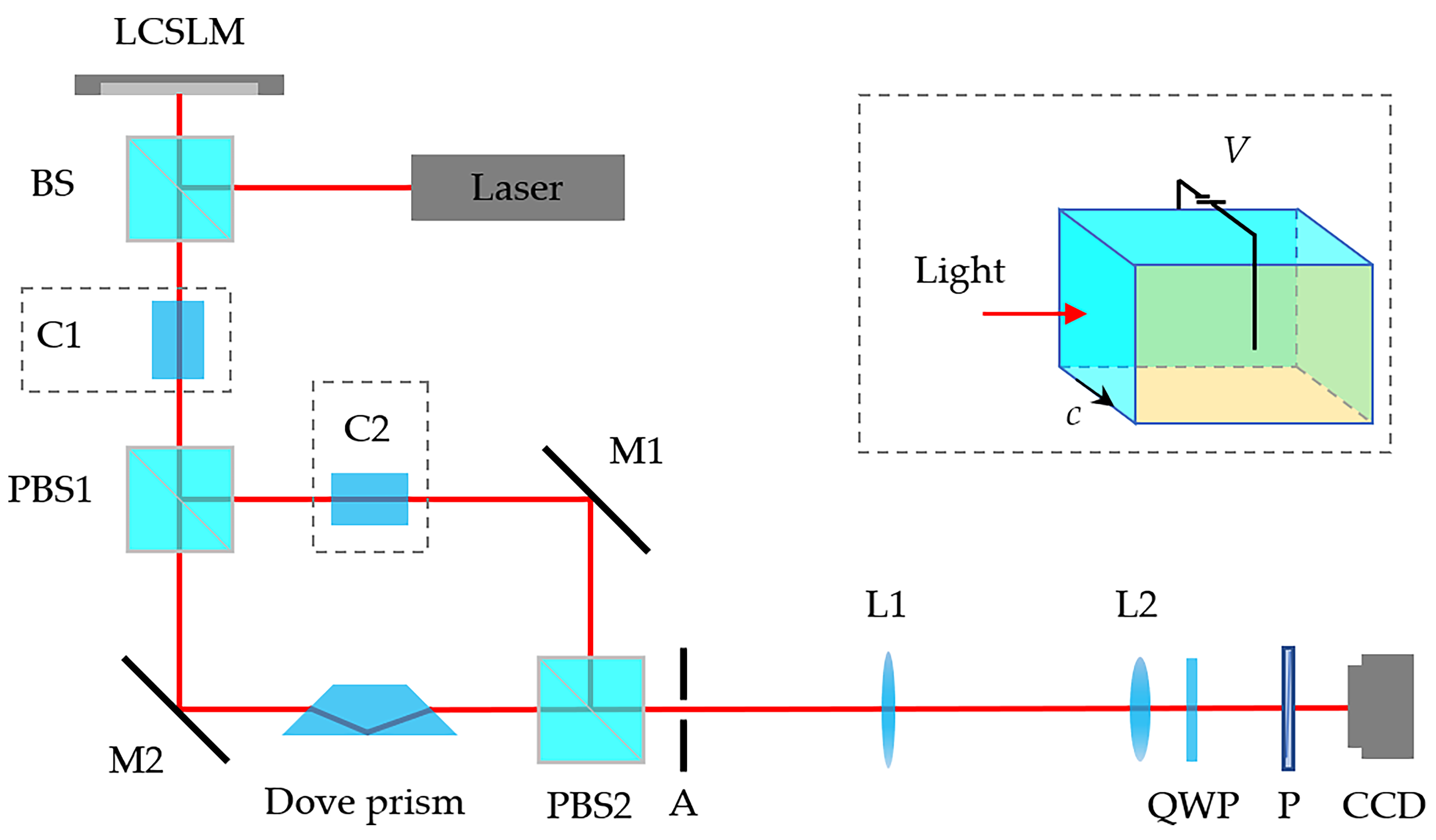
2. Method and Experimental Setup

Generally, the generation of VBs based on interferometers could be considered as a superposition of two eigenstates, such as the orthonormal circular polarization basis { e L , e R } , which could be expressed by Jones matrix [ 1 , ± i ] T / 2 , where the superscript T represents the transpose of the matrix. In the proposed system, cylindrical VBs at arbitrary points on the surface of the HOP sphere were generated, which is achieved by modulating the relative intensity and phase difference of these two eigenstates using two EO crystals. The schematic of the proposed HOP beams EO modulation system is shown in Figure 1. In simulation and experiments, two 98 %   KD 2 PO 4 (DKDP) crystals ( 10 × 10 × 20 mm , θ = 90 , φ = 45 ) were employed as EO modulator [27,28]. The EO coefficient of DKDP crystal used in experiments is γ 63 = 25.8 pm / V [29]. Those optical surfaces were polished and coated antireflection films at a wavelength of 633 nm . To realize EO modulation, two surfaces perpendicular to the crystal light axis were plated with an electrode. These crystals were packaged with insulating materials. A high-voltage generator with adjustment ranges from 0 to 10 kV and a precision of 0.2 kV was employed to adjust the applied electric field across the crystals. The relationship between directions of the light incident, the light-axis of crystal (c), and the applied voltage are shown in the dotted box of Figure 1.
In experiment, the laser source is a collimated expanded laser beam from He-Ne laser with wavelength λ = 632.8 nm and horizontal polarization. By means of Jones matrix, it could be expressed as [ 1 , 0 ] T . A reflective phase-only LCSLM (Holoeye, GAEA, nominal resolution 4000 × 2464 pixels, pixel pitch 3.74 µ m ) was used as vortex generator, a helical phase exp ( i l ϕ ) was displayed on it, where l is the topological charge of vortex phase. After being reflected by LCSLM, monochromatic planar light beam was converted into vortex beam with corresponding topological charge, [ exp ( i l ϕ ) , 0 ] T . The first EO crystal (C1) was used to modulate ellipticity of output field, and its light-axis was rotated along 45 . The Jones matrix of C1 could be expressed by
J C 1 = exp ( i 2 π n e L / λ ) R ( θ ) 1 0 0 exp [ i 2 π Γ ( E 1 ) L / λ ] R ( θ )
in which, Γ ( E 1 ) = n o n e 0.5 n o 3 γ 63 E 1 is the birefringence parameter of DKDP crystal in electric field, R ( θ ) is the Jones matrix for a coordinate rotation [30], θ = 45 , L is the length of EO crystal C1, γ 63 is the EO coefficient of DKDP crystal, n o and n e are ordinary and extraordinary index of DKDP crystal, respectively. E 1 = U 1 / d is the electric field applied on C1, where U 1 and d are applied voltage and distance between electrodes, respectively. The PBS1 splits vortex beam into transmission and reflection arms (i.e., p- and s-components). The intensity ratio of these two components is controlled by applied voltage (or electric field) on EO crystal C1, η ( E 1 ) = cot 2 [ π Γ ( E 1 ) L / λ ] . The p-component pass through Dove prism and inverse topological charge from l to + l , to make the two components with opposite helical phase front exp ( ± i l ϕ ) . The s-component pass through C2, which is the second EO modulator. The optical axis of C2 is horizontal and its length is same as C1. Phase shift introduced at C2 could be expressed as
Δ ϕ ( E 2 ) = 2 π ( n o 0.5 n o 3 γ 63 E 2 ) L / λ
where E 2 = U 2 / d is the applied electric field on C2, and U 2 is the value of applied voltage. The function of C2 is controlling phase difference between the two eigenstates and azimuth of generated HOP beams by the applied voltage U 2 . The position of M1 was adjusted accurately to make the phase difference of these two components is either 0 or 2 n π (where n is integer), when the applied voltage U 2 = 0 . After recombined by PBS2, these two beams pass through an aperture (A) to filter the outer stray light. The aperture could be described by circ ( r / R ) . The value of circ ( r / R ) is 1 for r < R , else circ ( r / R ) = 0 . The light field at aperture could be expressed as
u A = cos [ π Γ ( E 1 ) L / λ ] exp ( i l ϕ ) i sin [ π Γ ( E 1 ) L / λ ] exp ( i l ϕ ) exp [ i Δ ϕ ( E 2 ) ] exp [ i π Γ ( E 1 ) L / λ ] circ ( r / R )
Lenses L1 and L2 constitute a 4 f system to relay the field at aperture to charge coupled device (CCD). Quarter-wave plate (QWP) oriented at 45 converts horizontally and vertically polarized component into right- and left-handed circularly polarized (RCP and LCP) beam, respectively. Using the orthonormal circular polarization basis { e L , e R } , light field at recording plane could be expressed as
u R = cos [ π Γ ( E 1 ) L / λ ] exp ( i l ϕ ) exp [ i Δ ϕ ( E 2 ) 2 ] e R + i sin [ π Γ ( E 1 ) L / λ ] exp ( i l ϕ ) exp [ i Δ ϕ ( E 2 ) 2 ] e L
To make the expression concise, the constant phase factor is omitted here. In the equation above, the polarization states distribution is related to the spatial position and has a cylindrical symmetric structure.

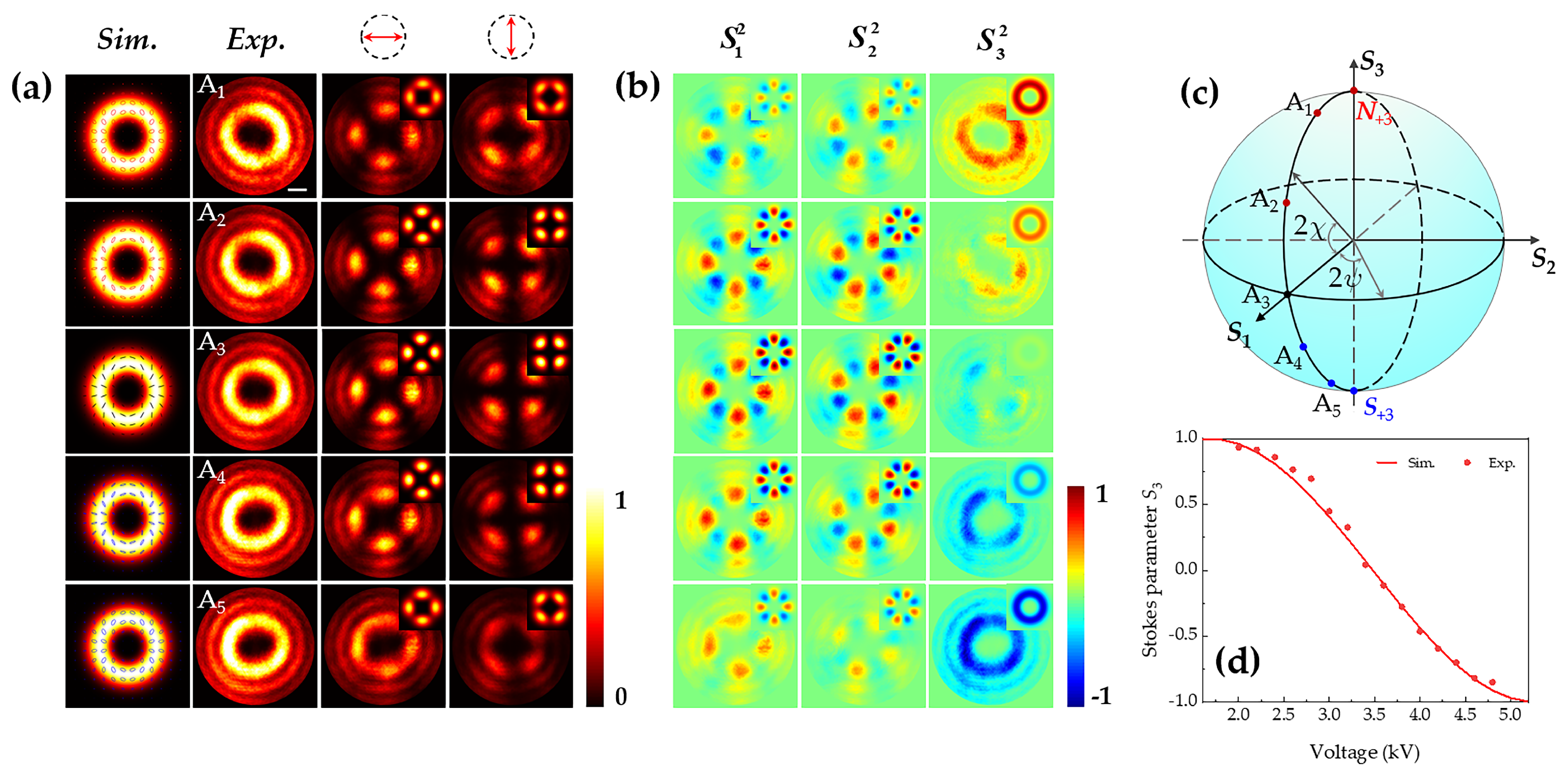
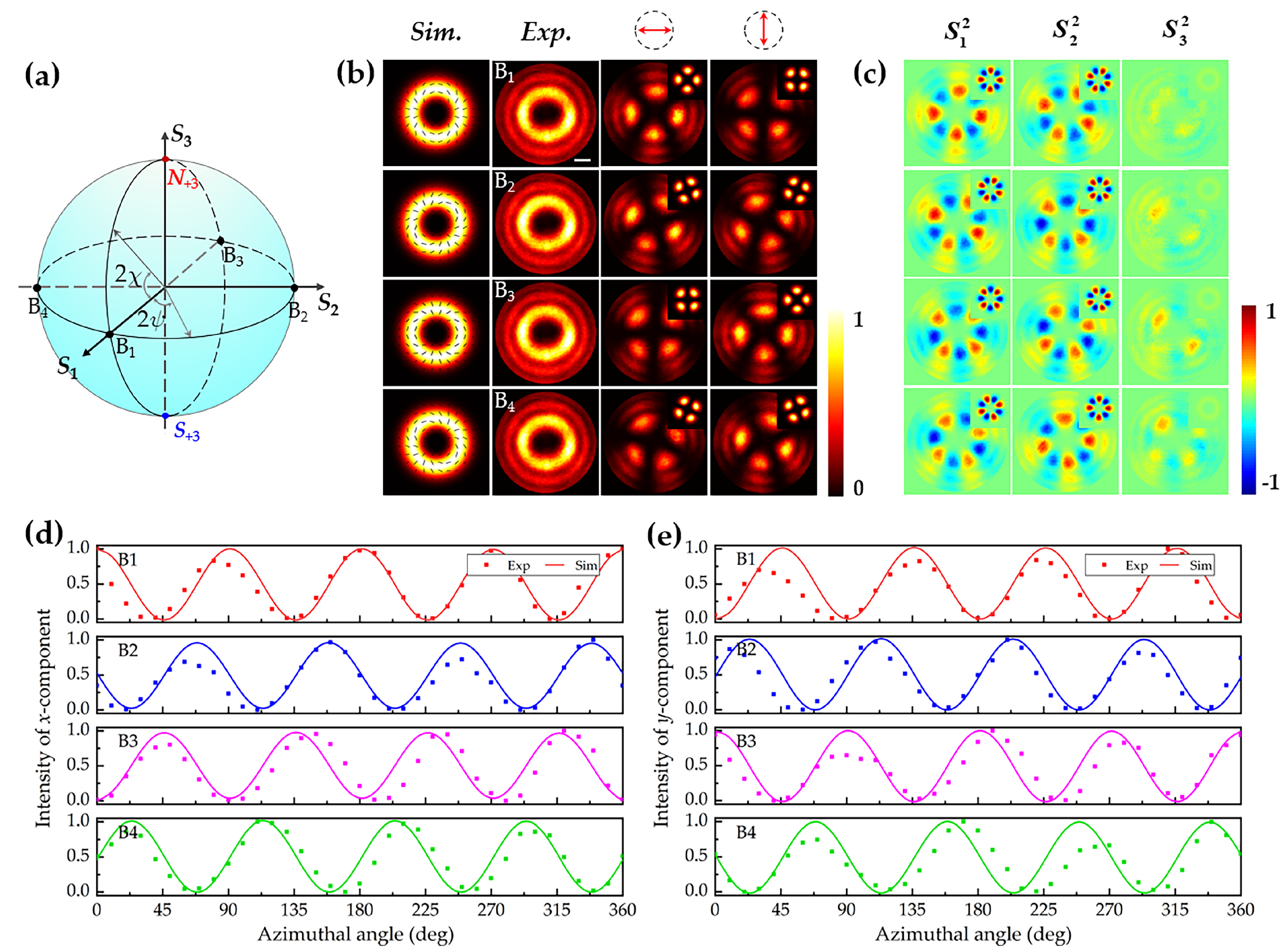
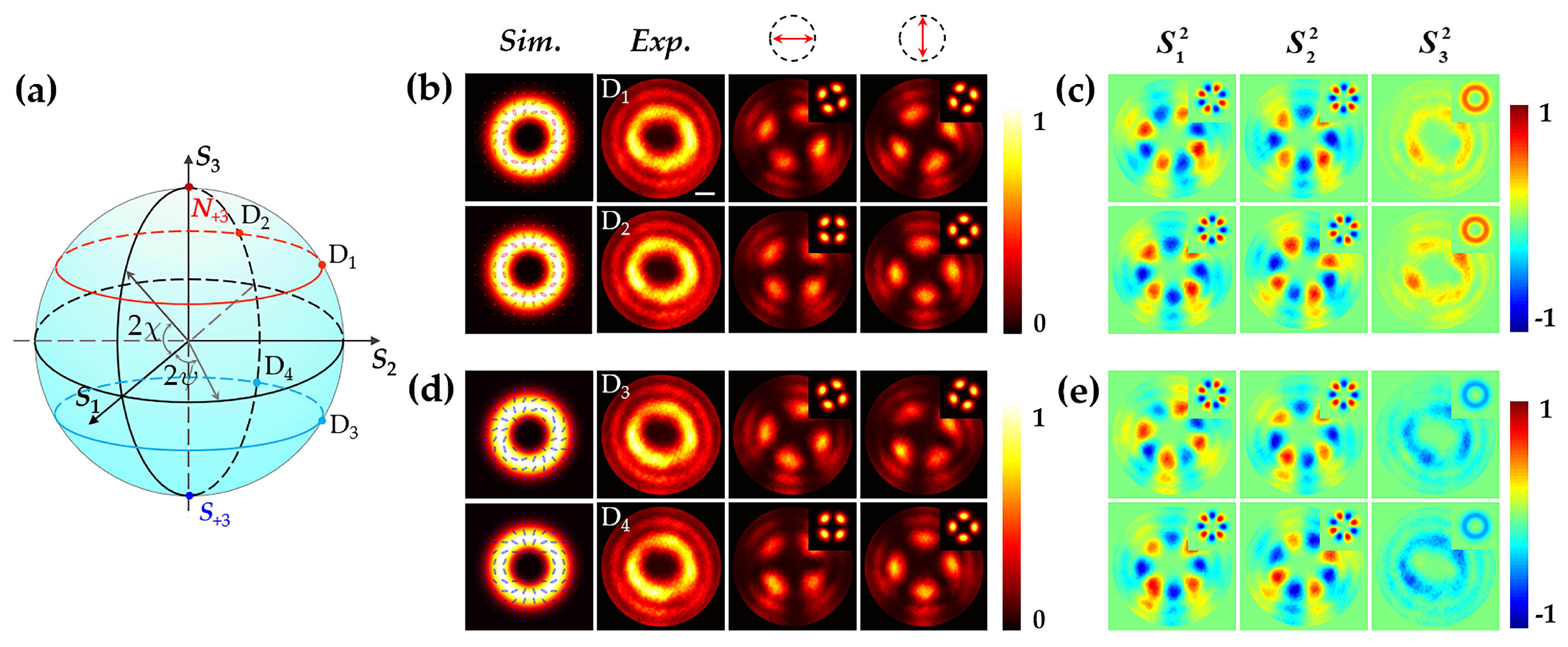
3. Experimental Results

To verify the proposed method and system, cylindrical VBs with different coordinates on the HOP sphere were generated in experiments. Intensity and Stokes parameters distribution was simulated based on Equation (5), and compared with experimental results. A Laguerre-Gaussian beam with topological charge l = 2 was employed to represent the vortex field in simulations. Firstly, just insert C1 into the system to generate cylindrical VBs at points on a line of longitude but with different latitudes, which is corresponding to HOP beams with different ellipticity. To achieve it, voltage U 1 was set as 2.2, 2.8, 3.4, 4.0 and 4.6 kV to generated cylindrical VBs on HOP sphere l = + 2 with 2 ψ = 0 and 2 χ is 0.353 π , 0.188 π , 0.045 π , 0.143 π and 0.309 π , respectively. The experimental and simulated results are shown in Figure 2. As shown in Figure 2c, the position of generated cylindrical VBs on the surface of the HOP sphere are labeled and signed as A1 to A5. Figure 2a shows the intensity pattern of generated cylindrical VBs. The polarization states are overlaid on simulated intensity pattern as shown in the first row of Figure 2a. Corresponding Stokes parameters distribution of generated cylindrical VBs are shown in Figure 2b. In Figure 2a, it is clear to see that the generated field has annular intensity distributions and a dark core, which demonstrate polarization and phase singularity. Four lobes in intensity pattern when the polarizer P along 0 and 90 corresponds to the N lobes with N = 2 | l | , where | l | is the order of polarization. The change of Stokes parameter S 3 in Figure 2b corresponds to the VBs going from the north to the south poles of the HOP sphere. For more intuitive, the experimental voltage modulating curve of Stokes parameter S 3 , when the applied voltage U 1 from 2.0 to 5.0 kV, was measured and compared with a simulated curve. These results are shown in Figure 2d, where the solid line and scattered dots are denote simulated and measured results, respectively.
To verify the ability of the proposed system to modulate azimuth of generated HOP beams polarization state, just C2 was inserted in the system and adjusted the applied voltage to generate cylindrical VBs at points on the equator but with different longitude on the HOP sphere. Four cylindrical VBs on HOP sphere with coordinates ( 0 , 0 ) , ( 0 , π / 2 ) , ( 0 , π ) , ( 0 , 3 π / 2 ) were generated. Their position on the HOP sphere is signed in Figure 3a with B1 to B4, respectively. To generate these four cylindrical VBs, a voltage applied on C2 was set as 0, 1.8, 3.6, and 5.4 kV, respectively. The distribution of polarization state is overlaid on simulated intensity pattern as shown in the first row of Figure 3b. The second to fourth rows of Figure 3b show the intensity pattern measured in experiments without and after polarizer with a different direction. Figure 3c shows the Stokes parameters distribution of generated cylindrical VBs. Corresponding simulated results are shown in insets. In Figure 3b, one could see the gaps between two adjacent lobes, which could be attributed to the linear polarization state of generated VBs. It could be confirmed by the Stokes parameter distribution shown in Figure 3c. The change of phase shift in Equation (3) caused by applied voltage U 2 would lead to rotation of polarization. Its performance in the experimental intensity pattern is the rotation of the gaps. In order to show the modulation effect of the applied voltage U 2 on the azimuth angle more intuitively and quantitatively, the azimuthal intensity data of generated cylindrical VBs, when the polarizer with directions 0 and 90 , was extracted and compared with the theoretical curve, which are corresponding to the x- and y-component of the output field. Figure 3d,e show the experimental data and the theoretical curves in the form of scattered dots and solid lines, respectively. The maximum and minimum positions in experimental intensity data are consistent with it in theoretical curves. The slight deviation between the experimental and theoretical curves was caused by spatial aberrations during the transmission of the vortex beam.
To further verify the proposed method, both C1 and C2 were inserted into the system and the applied voltage was controlled independently. This makes the system could modulate ellipticity and azimuth of generated cylindrical VBs’ polarization state simultaneously. We generated cylindrical VBs at the surface of the HOP sphere l = + 2 , the position of generated cylindrical VBs on the HOP sphere is shown in Figure 4a and signed as D1 to D4. In experiments, U 1 was set as 2.8 kV, and U 2 was set as 1.8 and 3.6 kV to generate cylindrical VBs at D1 ( 0.188 π , π / 2 ) and D2 ( 0.188 π , π ) , respectively. The polarization state distribution, intensity pattern without and after polarizer with different directions are shown in Figure 4b, while corresponding Stokes parameter distributions are shown in Figure 4c. To generate cylindrical VBs at D3 ( 0.143 π , π / 2 ) and D4 ( 0.143 π , π ) , the voltage of U 1 was set as 4.0 kV, while U 2 was set as 1.8 and 3.6 kV, respectively. The experimental and simulated results of generated cylindrical VBs at D3 and D4 are shown in Figure 4d,e.

4. Discussion

Simulated and experimental results shown in Figure 2 to Figure 4 verify the feasibility of the proposed method and system. The first EO modulator C1 is used to change the relative intensity of the two eigenstates and control the ellipticity of generated HOP beams, while the function of the second EO modulator C2 is controlling azimuth of generated HOP beams by changing the phase difference between the two eigenstates. Using the proposed method, cylindrical VBs at any point on the surface of the HOP sphere could be generated by controlling the voltage applied on the two EO modulated crystals. There is no need to move any optical element when changing output polarization state, and no mechanical vibrations, naturally. Furthermore, due to the flexibility of the voltage signal, the changing of polarization state could be direct and immediate, instead of bit by bit. Compared with changing polarization state by rotating wave plate, the proposed method based on EO modulation could make the polarization state switching more flexibly and fast. Besides, in terms of the selection of the voltage source, the introduction of a radio frequency field could realize high-frequency modulation of the polarization state.
In the simulations and experiments, the EO modulator is DKDP crystal with transverse EO modulation (applied electric field is perpendicular to wave vector of an incident beam), while in practical application, longitudinally EO modulated (applied electric field is parallel to wave vector of an incident beam) DKDP crystals or other EO crystals (such as lithium niobate, potassium titanyl phosphate and so on) are also an option. According to Equations (2) and (3), the phase shift caused by EO effect is function of EO coefficient, crystal length and electric field. So, crystals with a larger EO coefficient, longer crystal, and small distance between the electrodes could lower the required voltage. Due to the modulating rate depending on the switch rate of applied voltage, a lower required voltage is more beneficial to the fast switch polarization state of generated VBs. In the proposed method, a rotating wave plate is not needed, which means the whole system could be completely static, and electrodes are plated on the crystal surface that takes hardly any space. These make the whole system could be highly integrated. We hope this method could be used in small size components such as chips, in the future.

5. Conclusions

In this paper, a method to modulate the polarization states of HOP beams was proposed, and a system was designed to verify the proposed method based on Mach-Zehnder interferometers. In the proposed method, azimuth and ellipticity of generated cylindrical VBs were modulated by the EO effect of nonlinear optical crystal, which is achieved by controlling the voltage signal applied on EO crystals. There would be no optical element moving and mechanical vibrations when the output polarization state changes. Besides, due to the flexibility of the voltage signal, the polarization state could be switched directly and immediately. Simulated and experimental results verified the validity of the proposed method.

Author Contributions

Conceptualization, L.H. and D.L.; Formal analysis, L.H. and C.C.; Investigation, L.H. and Z.L.; Resources, Z.L. and X.S.; Supervision, D.L.; Writing—original draft, L.H.; Writing—review & editing, L.H., J.Z. and D.L. All authors have read and agreed to the published version of the manuscript.

Funding

This research was funded by the National Natural Science Foundation of China (11774364, 12004404, 61975218, 61905261); Shanghai Sailing Program (18YF1425900); and Strategic Priority Research Program of Chinese Academy of Sciences (Grant No. XDA25020302, Grant No. XDA25020202).

Data Availability Statement

The available data has been stated in the article.

Conflicts of Interest

The authors declare no conflict of interest.

References

  1. Zhan, Q. Cylindrical vector beams: From mathematical concepts to applications. Adv. Opt. Photon. 2009, 1, 1–57. [Google Scholar] [CrossRef]
  2. Chen, J.; Wan, C.; Zhan, Q. Vectorial optical fields: Recent advances and future prospects. Sci. Bull. 2018, 63, 54–74. [Google Scholar] [CrossRef] [Green Version]
  3. Zhang, C.; Du, L.; Xin, Z.; Si, G.; Yang, A.; Lei, T.; Lin, J.; Yuan, X. Polarization-to-phase coupling at a structured surface for plasmonic structured illumination microscopy. Laser Photon. Rev. 2018, 12, 1800148. [Google Scholar] [CrossRef]
  4. Yoshida, M.; Kozawa, Y.; Sato, S. Subtraction imaging by the combination of higher-order vector beams for enhanced spatial resolution. Opt. Lett. 2019, 44, 883–886. [Google Scholar] [CrossRef] [PubMed]
  5. Chen, J.; Wan, C.; Chong, A.; Zhan, Q. Subwavelength focusing of a spatio-temporal wave packet with transverse orbital angular momentum. Opt. Express 2020, 28, 18472–18478. [Google Scholar] [CrossRef]
  6. Zhang, Y.; Chen, J.; Bai, C.; Zhang, D.; Zhan, Q. Dynamical generation of multiple focal spot pairs with controllable position and polarization. Opt. Express 2020, 28, 26706–26716. [Google Scholar] [CrossRef]
  7. Salakhutdinov, V.; Sondermann, M.; Carbone, L.; Giacobino, E.; Bramati, A.; Leuchs, G. Optical trapping of nanoparticles by full solid-angle focusing. Optica 2016, 3, 1181–1186. [Google Scholar] [CrossRef]
  8. Kozawa, Y.; Sato, S. Optical trapping of micrometer-sized dielectric particles by cylindrical vector beams. Opt. Express 2010, 18, 10828–10833. [Google Scholar] [CrossRef] [PubMed]
  9. Drevinskas, R.; Zhang, J.; Beresna, M.; Gecevičius, M.; Kazanskii, A.G.; Svirko, Y.P.; Kazansky, P.G. Laser material processing with tightly focused cylindrical vector beams. Appl. Phys. Lett. 2016, 108, 221107. [Google Scholar] [CrossRef] [Green Version]
  10. Xian, M.; Xu, Y.; Ouyang, X.; Cao, Y.; Lan, S.; Li, X. Segmented cylindrical vector beams for massively-encoded optical data storage. Sci. Bull. 2020, 65, 2072–2079. [Google Scholar] [CrossRef]
  11. Wang, C.; Yang, B.; Cheng, M.; Cheng, S.; Liu, J.; Xiao, J.; Ye, H.; Li, Y.; Fan, D.; Chen, S. Cylindrical vector beam multiplexing for radio-over-fiber communication with dielectric metasurfaces. Opt. Express 2020, 28, 38666–38681. [Google Scholar] [CrossRef]
  12. Lai, W.J.; Lim, B.C.; Phua, P.B.; Tiaw, K.S.; Teo, H.H.; Hong, M.H. Generation of radially polarized beam with a segmented spiral varying retarder. Opt. Express 2008, 16, 15694–15699. [Google Scholar] [CrossRef] [PubMed]
  13. Li, S.M.; Qian, S.X.; Kong, L.J.; Ren, Z.C.; Li, Y.; Tu, C.; Wang, H.T. An efficient and robust scheme for controlling the states of polarization in a Sagnac interferometric configuration. Europhys. Lett. 2014, 105, 64006. [Google Scholar] [CrossRef]
  14. Kozawa, Y.; Sato, S. Generation of a radially polarized laser beam by use of a conical Brewster prism. Opt. Lett. 2005, 30, 3063–3065. [Google Scholar] [CrossRef]
  15. Chen, P.; Ji, W.; Wei, B.Y.; Hu, W.; Chigrinov, V.; Lu, Y.Q. Generation of arbitrary vector beams with liquid crystal polarization converters and vector-photoaligned q-plates. Appl. Phys. Lett. 2015, 107, 241102. [Google Scholar] [CrossRef]
  16. Lou, S.; Zhou, Y.; Yuan, Y.; Lin, T.; Fan, F.; Wang, X.; Huang, H.; Wen, S. Generation of arbitrary vector vortex beams on hybrid-order Poincaré; sphere based on liquid crystal device. Opt. Express 2019, 27, 8596–8604. [Google Scholar] [CrossRef]
  17. Wang, D.; Liu, T.; Zhou, Y.; Zheng, X.; Sun, S.; He, Q.; Zhou, L. High-efficiency metadevices for bifunctional generations of vectorial optical fields. Nanophotonics 2021, 10, 685–695. [Google Scholar] [CrossRef]
  18. Milione, G.; Evans, S.; Nolan, D.A.; Alfano, R.R. Higher Order Pancharatnam-Berry Phase and the Angular Momentum of Light. Phys. Rev. Lett. 2012, 108, 190401. [Google Scholar] [CrossRef] [PubMed]
  19. Chen, S.; Zhou, X.; Liu, Y.; Ling, X.; Luo, H.; Wen, S. Generation of arbitrary cylindrical vector beams on the higher order Poincaré sphere. Opt. Lett. 2014, 39, 5274–5276. [Google Scholar] [CrossRef] [PubMed] [Green Version]
  20. Chen, C.; Zhang, Y.; Ma, L.; Zhang, Y.; Li, Z.; Zhang, R.; Zeng, X.; Zhan, Z.; He, C.; Ren, X.; et al. Flexible generation of higher-order Poincaré beams with high efficiency by manipulating the two eigenstates of polarized optical vortices. Opt. Express 2020, 28, 10618–10632. [Google Scholar] [CrossRef]
  21. Gao, Y.; Chen, Z.; Ding, J.; Wang, H.T. Single ultra-high-definition spatial light modulator enabling highly efficient generation of fully structured vector beams. Appl. Opt. 2019, 58, 6591–6596. [Google Scholar] [CrossRef] [PubMed]
  22. Mellado-Villaseñor, G.; Aguirre-Olivas, D.; Arrizón, V. Generation of vector beams using synthetic phase holograms. J. Opt. Soc. Am. A 2021, 38, 1094–1103. [Google Scholar] [CrossRef]
  23. Liu, S.; Qi, S.; Zhang, Y.; Li, P.; Wu, D.; Han, L.; Zhao, J. Highly efficient generation of arbitrary vector beams with tunable polarization, phase, and amplitude. Photon. Res. 2018, 6, 228–233. [Google Scholar] [CrossRef]
  24. Xie, Y.; Yang, Y.; Han, L.; Yue, Q.; Guo, C. Generation of arbitrary vector beams based on a single spatial light modulator and a thin-film polarization splitting cubic. Chin. Opt. Lett. 2016, 14, 122601. [Google Scholar] [CrossRef]
  25. Holleczek, A.; Aiello, A.; Gabriel, C.; Marquardt, C.; Leuchs, G. Classical and quantum properties of cylindrically polarized states of light. Opt. Express 2011, 19, 9714–9736. [Google Scholar] [CrossRef] [Green Version]
  26. Milione, G.; Sztul, H.I.; Nolan, D.A.; Alfano, R.R. Higher-order Poincaré sphere, Stokes parameters, and the angular momentum of light. Phys. Rev. Lett. 2011, 107, 053601. [Google Scholar] [CrossRef] [PubMed]
  27. Nikogosyan, D. Nonlinear Optical Crystals: A Complete Survey; Springer: New York, NY, USA, 2006. [Google Scholar]
  28. Boyd, R. Nonlinear Optics; Elsevier Science: Hoboken, NJ, USA, 2020. [Google Scholar]
  29. Sun, Z.; Cui, Z.; Sun, M.; Yuan, Y.; Li, Q.; Liu, D.; Zhu, J. Electro-optic coefficient measurement of a K(H1−xDx)2PO4 crystal based on χ(2) nonlinear optical technology. Opt. Express 2021, 29, 2647–2657. [Google Scholar] [CrossRef]
  30. Goodman, J. Introduction to Fourier Optics; McGraw-Hill Physical and Quantum Electronics Series; W. H. Freeman: New York, NY, USA, 2005. [Google Scholar]
Figure 1. Schematic of proposed higher-order Poincaré (HOP) beams electro-optic (EO) modulation system. The dotted box in upper right corner shows the diagram of applying voltage to EO crystal. LCSLM: liquid crystal spatial light modulator; BS: beam splitter; C1, C2: EO crystal; PBS1, PBS2: polarized beam splitter; M1, M2: mirror; A: aperture; L1, L2: lens; QWP: quarter-wave plate; P: polarizer; CCD: charge coupled device.
Photonics 09 00041 g001
Figure 2. Simulated and experimental results of generated cylindrical VBs along longitude of HOP sphere l = + 2 with 2 ψ = 0 . (a) Intensity pattern of generated cylindrical VBs from A1 to A5, when the applied voltage on C1 is 2.2, 2.8, 3.4, 4.0, and 4.6 kV, respectively. The first and second rows show the simulated and experimental intensity pattern with no polarizer, respectively. Polarization states are overlaid on simulated intensity pattern. The other two rows show the intensity pattern measured in experiments when the polarizer is along horizontal and vertical directions, respectively, and the corresponding simulated results are shown in insets. (b) Stokes parameters distribution of A1 to A5, respectively. (c) HOP of l = + 2 . The position of generated cylindrical VBs on the HOP sphere is labeled by A1 to A5 along longitude with 2 ψ = 0 . (d) Curve of Stokes parameter S 3 and applied Voltage U 1 , the solid line and dots denote simulated and experimental result, respectively. Scale bar in the first experimental intensity pattern of A1 represents 0.645 mm.
Photonics 09 00041 g002
Figure 3. Simulated and experimental results of generated cylindrical VBs on the equator of HOP sphere l = + 2 with different longitude. (a) The position of generated cylindrical VBs on the equator of HOP sphere, which are signed by B1 to B4; (b) Intensity pattern of generated cylindrical VBs from B1 to B4. Simulated polarization states and intensity pattern are shown in the first row. The other rows from left to right are intensity pattern measured without polarizer and after polarizer with directions 0 and 90 , respectively; (c) Stokes parameters distribution of generated cylindrical VBs measured in experiments. The corresponding simulated results of intensity pattern and Stokes parameters distribution are shown in insets; (d,e) the azimuthal intensity distribution of x- and y-component, where the experimental data and the theoretical curves are shown with scattered dots and solid line, respectively. Scale bar in the first experimental intensity pattern of B1 represents 0.645 mm.
Photonics 09 00041 g003
Figure 4. Simulated and experimental results of generated cylindrical VBs when both C1 and C2 were inserted in the system. (a) The position of generated cylindrical VBs on HOP sphere, which are signed by D1 to D4 with coordinate ( 0.188 π , π / 2 ) , ( 0.188 π , π ) , ( 0.143 π , π / 2 ) and ( 0.143 π , π ) , respectively; (b,d) are intensity pattern of generated cylindrical VBs at point D1 to D4; (c,e) are corresponding Stokes parameters distribution. The first row of (b,d) shows the simulated polarization states and intensity pattern of generated cylindrical VBs, while the other rows from left to right are intensity pattern measured without polarizer and after polarizer with directions 0 and 90 , respectively. The corresponding simulated results of intensity pattern and Stokes parameters distribution are shown in insets. Scale bar in the first experimental intensity pattern of D1 represents 0.645 mm.
Photonics 09 00041 g004
Publisher’s Note: MDPI stays neutral with regard to jurisdictional claims in published maps and institutional affiliations.

