1. Introduction
With the development of big data analysis and cloud computing technology, traditional communication methods are far from meeting people’s increasing demand for information. All-optical network communication [
1,
2,
3] has the advantages of super-large capacity, super-high speed, high-quality, high-performance transmission, etc. It is an emerging technology to improve the amount of communication information. The construction of all-optical networks requires the support of high-performance optical devices [
4,
5,
6]. Photonic crystal fiber (PCF) has become the first choice for preparing optical devices because of its excellent performance and low cost. Researchers have designed optical devices such as PCF sensors [
7], PCF beam splitters [
8] and PCF filters [
9,
10] according to the flexible internal structure of PCF. The inside of PCF [
11,
12,
13,
14] is composed of many periodically arranged pores. By changing the structure and layout of the pores, the symmetry can be broken, so that it has many characteristics that traditional optical fibers do not have, such as ultra-low propagation loss [
15], polarization effect [
16], chromatic dispersion [
17], high nonlinear [
18], endless single mode transmission [
19], large mode area [
20], ultra high or low birefringence [
21], and so on.
Using the birefringence characteristics of PCF, the x and y orthogonal polarization beams can be separated within a short distance. Through this characteristic, many researchers have designed PCF polarization beam splitters. In 2014, Chen et al. [
22] proposed a liquid crystal modulation core dual-core silica glass PCF polarization splitter. The separate length is 0.175 mm, and the extinction ratio is −80.7 dB at the communication wavelength of 1550 nm. In the same year, Fan et al. [
23] designed a kind of dual-core gold-filled PCF polarization beam splitter. The splitting length of the polarization beam splitter is 1.746 mm, and the extinction ratios are −58 dB and −60 dB at the wavelengths of 1.327 um and 1.55 um, respectively. In 2015, Khaleque et al. [
24] reported a gold filled twin-core PCF polarization splitter. The beam splitting length and extinction ratio are 254.6
m and −111 dB, respectively. In 2016, Zi et al. [
25] designed a ultra-short polarization beam splitter based on liquid-filled PCF. The separate length is 139
m, but the extinction ratio is only −57.1 dB at the communication wavelength of 1.31
m. In 2017, Wang et al. [
26] reported a square lattice twin-core PCF polarization beam splitter. There are two ellipses near the core of the structure. By adjusting ellipticity, the beam splitting length is shortened to 93.3
m, and the extinction ratio is −79.3 dB. In the same year, Hagras et al. [
27] presented an ultra-compact soft glass PCF polarization beam splitter centered on chalcogenide glass
. The separate length is 111.244
m, however, the extinction ratio is only −55 dB at the wavelength of 1.55
m. In 2018, He et al. [
26] reported a tellurite glass twin-core PCF polarization splitter. The beam splitting length is 89.05
m, and the extinction ratio is 107.21 dB at the wavelength of 1.55
m. However, this structure has continuously added seven ellipses near the core, which is difficult to produce in the actual process. In 2020, Chen et al. [
28] reported a twin-core PCF polarization beam splitter based on thin layer
. The separate length is 1.0 mm, and the extinction ratio is −83.6 dB at the wavelength of 1.55
m. In the same year, Juan et al. [
29] proposed a helically twisted dual-core PCF polarization beam splitter. The splitting length of 24.76 mm and the extinction ratio of 50 dB are obtained at the wavelength of 1550 nm for a twist-rate of 15.70 rad/mm. In 2021, Qu et al. [
30] proposed a liquid crystal-filled twin-core PCF polarization beam splitter, which has a beam splitting length of 94
m. In the same year, Nelson et al. [
31] proposed a thermo-optically tunable gold-filled dual-core PCF polarization beam splitter. The bandwidth and extinction ratio of the polarization beam splitter are 9 nm and −83.2 dB, respectively, and the tuning sensitivity is 67 and 66 pm/
C.
In this paper, a circular ultra-short dual-core PCF polarization beam splitter is proposed. The dual-core coupling performance is improved by filling high refractive index in the central air hole. A large number of simulation results show that when the communication wavelength is 1.55 m, the coupling ratio between the y and x polarization directions can reach the ideal value of 2. By optimizing the geometric parameters of PCF pore structure, the splitting length of the polarization beam splitter can be as short as 72.43 m, and the extinction ratio can reach −151.42 dB. The high extinction ratio makes the circular polarization beam splitter have a good beam splitting function. The designed circular double-core PCF has the same cladding pore diameter, which is easier to prepare than other PCFs with complex pore structure. The extremely short beam splitting length and high extinction ratio make the PCF polarization beam splitter of this structure have important value in optical device applications.
2. The Structure and Theoretical Analysis
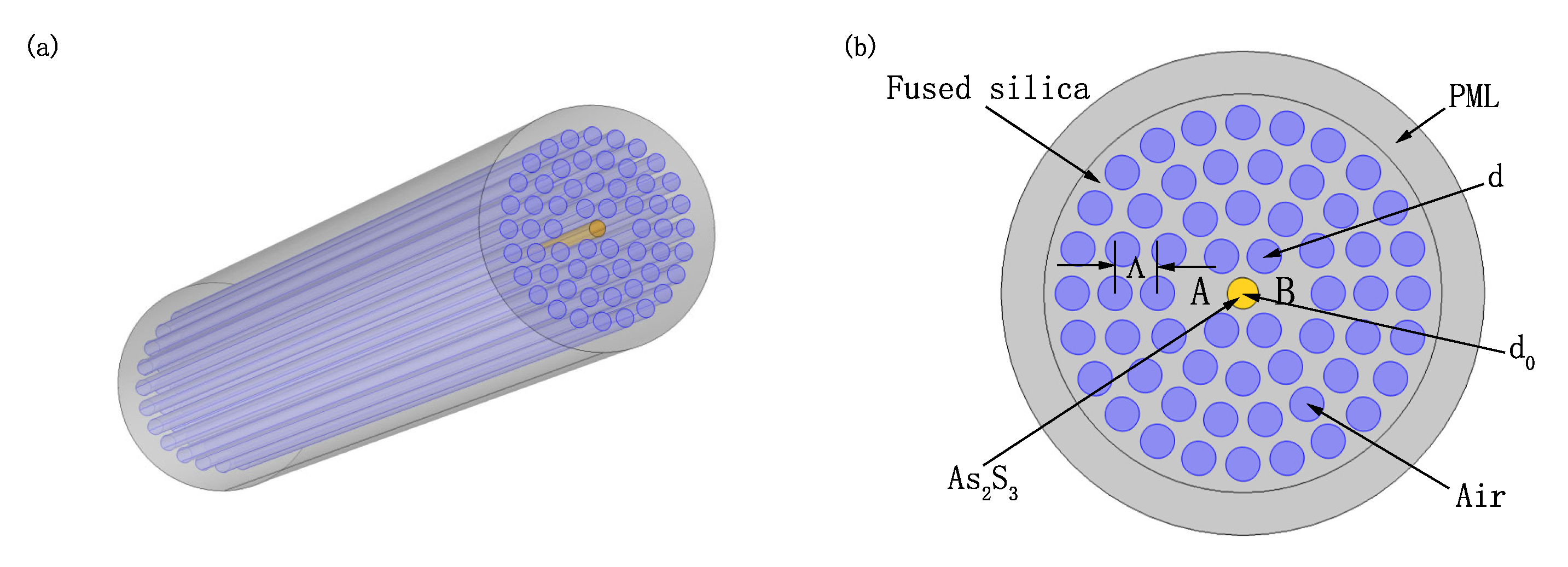
Figure 1 shows a circular extremely short double-core PCF polarization beam splitter with
filled in the center air hole, wherein
Figure 1a is its three-dimensional schematic view and
Figure 1b is its two-dimensional end view. From
Figure 1b, the air holes are arranged in a circular lattice array structure. The diameter of the cladding pores is
d, and the distance between two adjacent pores is represented by
. The background material of PCF is molten fused silica, and its dispersion relation can be expressed by Sellmeier equation [
32]:
where the unit of
is micron. The yellow part is sulfide
, and its diameter is
. The Sellmeier equation for determining the dispersion properties of
glass is [
33]:
where
i = 5,
,
= 0.15
m,
,
= 0.25
m,
,
= 0.35
m,
,
= 0.45
m,
,
= 27.3861
m. A and B adjacent to
are two cores, and
in the middle position enhances the coupling degree of the two cores. The finite element method (FEM) is used to study the performance of the designed PCF polarization beam splitter. Mesh is an important concept in finite element method. The more precise the mesh division, the higher the degree of discretization, and the smaller the difference between the simulation result and the exact solution. However, with the grid encryption, the scale of calculation and the required storage space will multiply, and the computational efficiency will be lower. For plane structure, the grid division is generally triangular or quadrilateral. This design adopts free triangular mesh. In order to effectively absorb the radiant energy of light waves, a circular perfect matching layer (PML) is added to the periphery of PCF in the simulation process. The diameter of PML is 17
m and the thickness is 3
m. In addition, the energy reflection is further reduced by adding scattering boundary conditions on the periphery of the PML region.
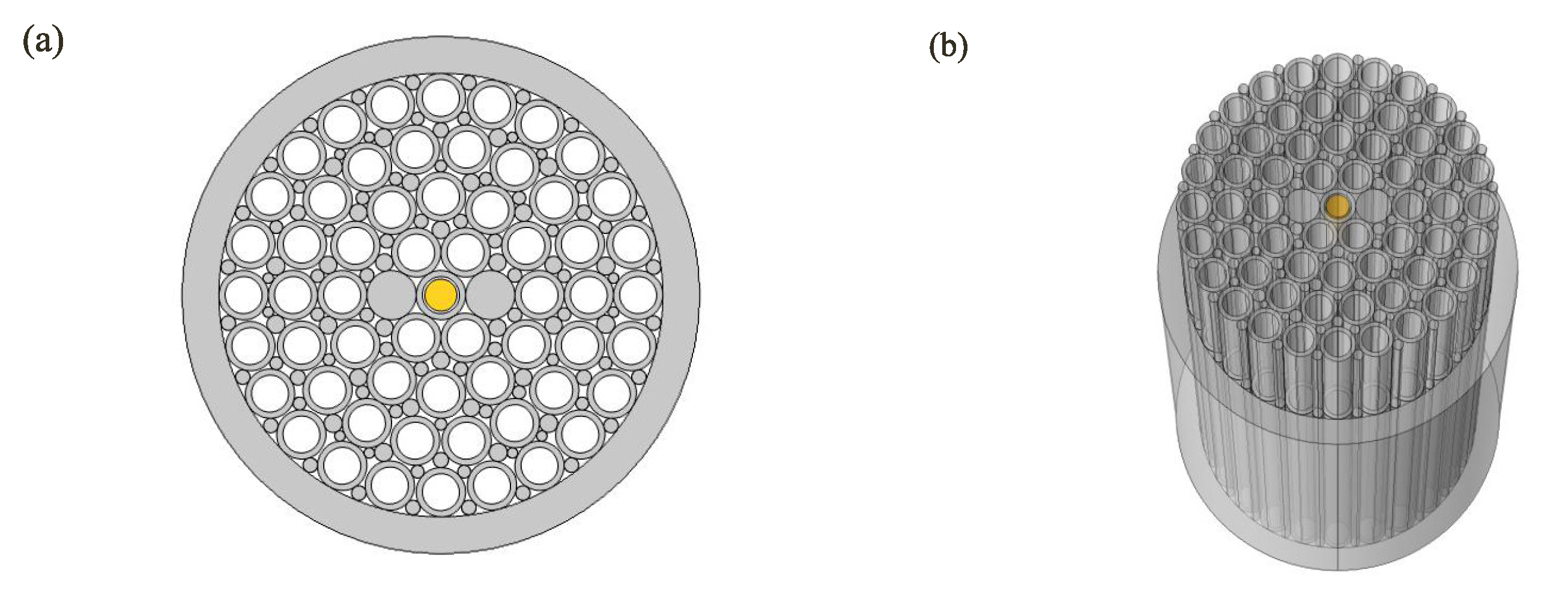
Figure 2 is a schematic diagram of the double-core circular PCF preform prepared by stacking method, in which
Figure 2a is a two-dimensional end view, and
Figure 2b is a three-dimensional schematic diagram. From
Figure 2a, the success rate of the PCF preparation is higher because of the uniform size of the cladding pores. When preparing the preform, the preform is stacked layer by layer from the inside to the outside, and a total of four layers are stacked. After each layer of hollow capillaries is stacked, the calculated thin capillary rods are used for stacking to fill the gaps and make the pore structure of the PCF cladding appear round. Two capillaries adjacent to the central capillary in the horizontal direction are replaced by solid capillary rods with the same diameter, so that the optical fiber forms a double-core structure. Insert the chalcogenide
capillary rod into the central capillary. Since the melting point of
is much lower than that of quartz glass, the
capillary rod will melt first during the PCF drawing process. The central capillary will be filled with melted
, so the inner diameter of central capillary determines the final diameter of
. In the process of drawing PCF, it is necessary to observe the end face of PCF in real time by optical microscope. According to the end structure of PCF, timely adjust the drawing parameters so as to prepare double-core circular
-filled PCF. If the diameter of
in the prepared PCF is too large, the capillary with small inner diameter should be placed in the center when stacking preforms, otherwise, the capillary with large inner diameter should be placed in the center.
Dimensional tolerance is very important for the preparation of PCF. Smaller PCF diameter tolerance will help to reduce joint loss and improve the splicing efficiency of PCF. The diameter tolerance of PCF can be controlled by adjusting the drawing parameters. For example, when the diameter of PCF is too large, it is necessary to reduce the rod feeding speed or increase the pulling speed. When the PCF diameter is too small, it is necessary to increase the rod feeding speed or reduce the pulling speed. In the process of preparing PCF, besides PCF diameter tolerance, it is also necessary to consider PCF inner cladding pore diameter tolerance. During the preparation process, the pore diameter of PCF cladding can be observed in real time by optical microscope. Introducing gas into the cladding pores can not only prevent the cladding pores from collapsing, but also adjust the diameter of the cladding pores. If the diameter of cladding pores is too large, the air pressure should be reduced. If the diameter of cladding pores is too small, the air pressure should be increased. Since the PCF cladding pores designed in this paper have the same size, the PCF cladding pores of this structure can be inflated or pumped as a whole. This also shows that compared with other complex cladding pore structures, the PCF structure designed in this paper is easier to reduce the tolerance of cladding pore diameter during the preparation process.
Dual-core PCF has two types of eigenmodes, one is symmetric mode, called even mode, and the other is antisymmetric mode, called odd mode. Since there are two polarization directions, there are four supermodes in the dual-core PCF, that is, even mode and odd mode in x-polarized direction, and even mode and odd mode in y-polarized direction. The coupling length is the shortest distance between the two cores when the maximum power transmission occurs, and its length directly reflects the strength of the coupling. The coupling length [
34] of the dual-core PCF can be calculated by Formula (1).
where
and
are the transmission constants of even and odd modes in x- and y-polarized directions,
represents the wavelength of incident light.
and
are the mode effective refractive indices of even and odd modes in x- and y-polarized directions, respectively.
The condition for separating the two polarizations of
x and
y is that the fiber length meets
L =
m =
n, where
L represents the length of PCF.
m and
n are positive integers, and their parity is opposite. The coupling length ratio (CLR) refers to the ratio of the coupling length of x- and y-polarized light. It is an important indicator to measure whether the double-core PCF beam splitter can achieve effective beam splitting. Its formula is defined as [
35]:
When the CLR value is
or 2, the x- and y-polarized lights of the double-core PCF beam splitter are completely separated, and the length of PCF is the best beam splitting length. When the value is
, it means that when y-polarized light completes half-period coupling, x-polarized light has completed one-period coupling. When light propagates in a double-core PCF, it can couple from one core to another periodically. The ratio of the power at the output end of the core to the power at the input end is called the normalized power, which is defined as [
36]:
where
is the input power of two polarized lights and
is the output power of two polarized lights.
L is the transmission length and
is the coupling length.
3. Simulation Results and Analysis
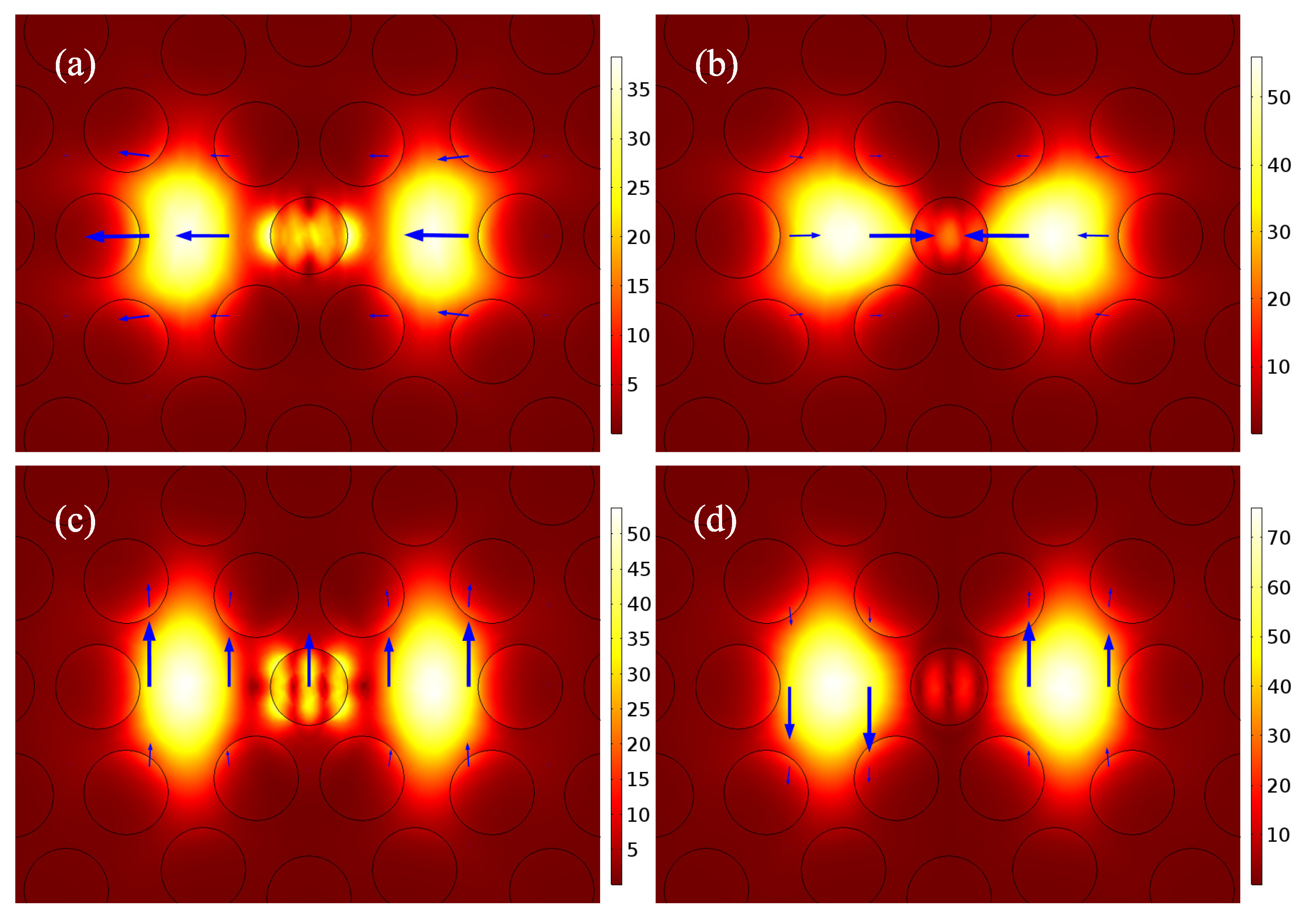
Figure 3 shows the electric field distribution of the four supermodes of the circular double-core PCF beam splitter at the wavelength of 1.55
m. By filling sulfide
into the central air hole, a light guide band is formed between the two fiber cores, thus enhancing the coupling strength of x-polarized light and y-polarized light.
Figure 3a,c show the even-mode electric field distribution in x- and y-polarized directions, and
Figure 3b,d show the odd-mode electric field distribution in x- and y-polarized directions. From
Figure 3a,c, the energy of PCF core mode is coupled to the surface of
glass rod, while almost no energy is coupled to the surface of
glass rod in
Figure 3b,d. This indicates that even modes in x- and y-polarized directions and modes on chalcogenide glass rods satisfy the phase matching condition at the wavelength of 1.55
m, while odd modes in x- and y-polarized directions and modes on chalcogenide glass rods do not satisfy the phase matching condition. In addition, this also shows that surface plasmon waves can be generated not only on the metal surface, but also on the high refractive index chalcogenide glass surface, that is, the surface plasmon-like mode can be formed on the surface of the high refractive index rod. When the PCF core mode and the
rod surface mode satisfy the phase matching condition, the PCF core energy will be coupled to the
rod surface.
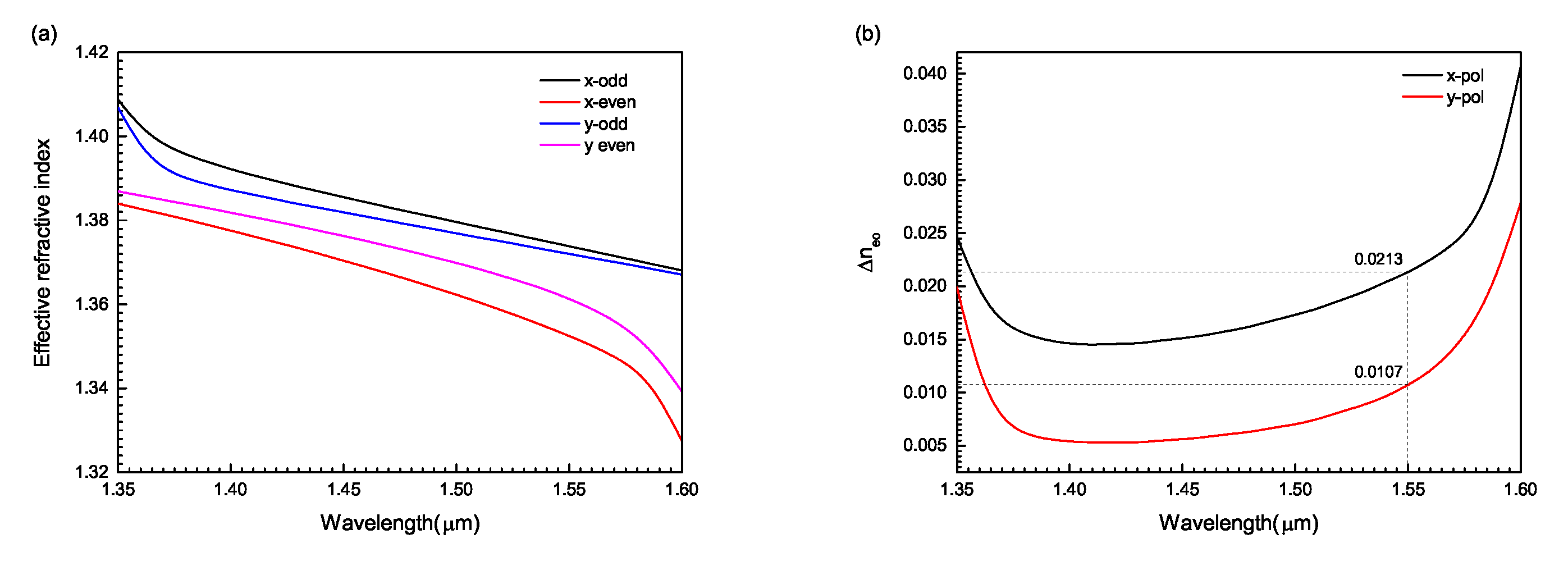
Figure 4 shows the variation of the effective refractive index and the effective refractive index difference of the circular double-core PCF with wavelength. From
Figure 4a, as the wavelength increases, the effective refractive index gradually decreases. According to Formula (1), the coupling length is inversely proportional to the refractive index difference at the same wavelength. From
Figure 4b, at the wavelength of 1.55
m, the refractive index difference in y-polarized direction is 0.0107, while that in the x-polarized direction is 0.0213, and the refractive index difference in the y-polarized direction is approximately one-half of that in the x-polarized direction, that is, the coupling length in the y-polarized direction is approximately twice that in the x-polarized direction, which makes the circular PCF structure realize extremely short beam splitting.
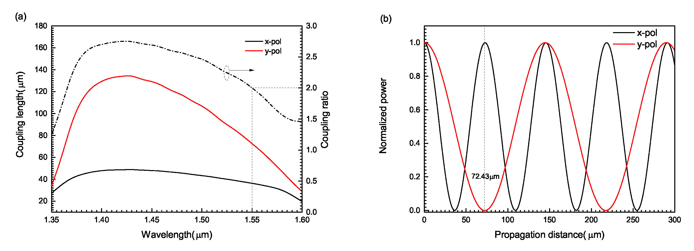
The variation of the coupling length of circular two-core PCF with wavelength and the variation of the normalized power with distance are shown in
Figure 5. From
Figure 5a, as the wavelength increases from 1.35 to 1.60
m, the coupling length in the x- and y-polarized directions first increases and then decreases, and the coupling ratio between them also first increases and then decreases. At the communication wavelength of 1.55
m, the coupling ratio reaches the best value of 2. In addition, at the same wavelength, the coupling length in the x-polarized direction is much smaller than that in the y-polarized direction, because the coupling strength between the mode on the surface of
rod and the core mode in the x-polarized direction is much stronger than that in the y-polarized direction. From
Figure 5b, when the wavelength of the input light wave is 1.55
m, the coupling lengths in x- and y-polarized directions are 36.38
m and 72.43
m, respectively, which basically meets 2
=
=
m. Therefore, the two polarized lights can be completely separated. This shows that when the length of the polarization beam splitter is 72.43
m, the core of the incident light only has the light in the x-polarized direction, while the light in the y-polarized direction has been completely coupled into another core, so the circular double-core PCF with this length can be made into a polarization beam splitter. The beam splitting length of x- and y-polarized light in the circular dual-core PCF is 72.43
m, which is difficult to operate in practical preparation. However, in the dual-core PCF, the coupling and splitting of x- and y-polarized light in the two cores is periodic, so the splitting effect can still be achieved after the splitting length is multiplied by different multiples. Since the beam splitting length of the circular dual-core PCF belongs to the extremely short beam splitting, the number of beam splitting lengths obtained by multiplying it by different multiples is more, so more beam splitting lengths are selected during preparation. Among the polarization beam splitters reported at present, the beam splitting length of this structure is relatively short, which is of great significance to the future application of this polarization beam splitter.
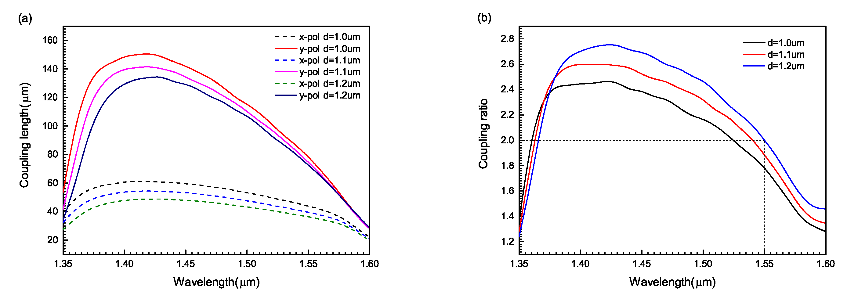
Two-core PCF takes the core as the center. Due to the asymmetric structure around the core, the fiber obtains large birefringence. Birefringence shows that the effective refractive index of x- and y-polarized modes is different, so the coupling length in the x- and y-polarized directions is different. Changing the cladding pore diameter of the dual-core PCF can change the asymmetry of the structure around the core, and then the coupling length can be changed accordingly. When
core diameter is 1.098
m, the variation of coupling length and coupling ratio with the increase of cladding pore diameter is shown in
Figure 6. From
Figure 6a, as the wavelength increases from 1.35 to 1.60
m, the coupling lengths in both x- and y-polarized directions increase at first and then decrease. For the same wavelength, when the cladding pore diameter is selected as 1.0
m, 1.1
m and 1.2
m in turn, the PCF coupling length decreases in turn. This shows that with the increase of the diameter of cladding pores, the cladding pores around the core become more compact, which makes it easier for the optical field energy to couple from one core to another, thus reducing the coupling length. In addition, the diameter of the cladding pores becomes larger, resulting in an increase in the asymmetry of the structure around the core, so the birefringence characteristics of the fiber are strengthened, and the coupling length is reduced. From
Figure 6b, the coupling ratio of different cladding pore diameters increases at first and then decreases. As the cladding pore diameter increases from 1.0 to 1.2
m, the coupling ratio decreases at short wavelengths and increases at long wavelengths. Furthermore, when the diameter of cladding pores is 1.2
m, the coupling ratio obtains the ideal value of 2 at the wavelength of 1.55
m. Therefore, the desired spectroscopic effect can be obtained by adjusting the appropriate cladding pore diameter.
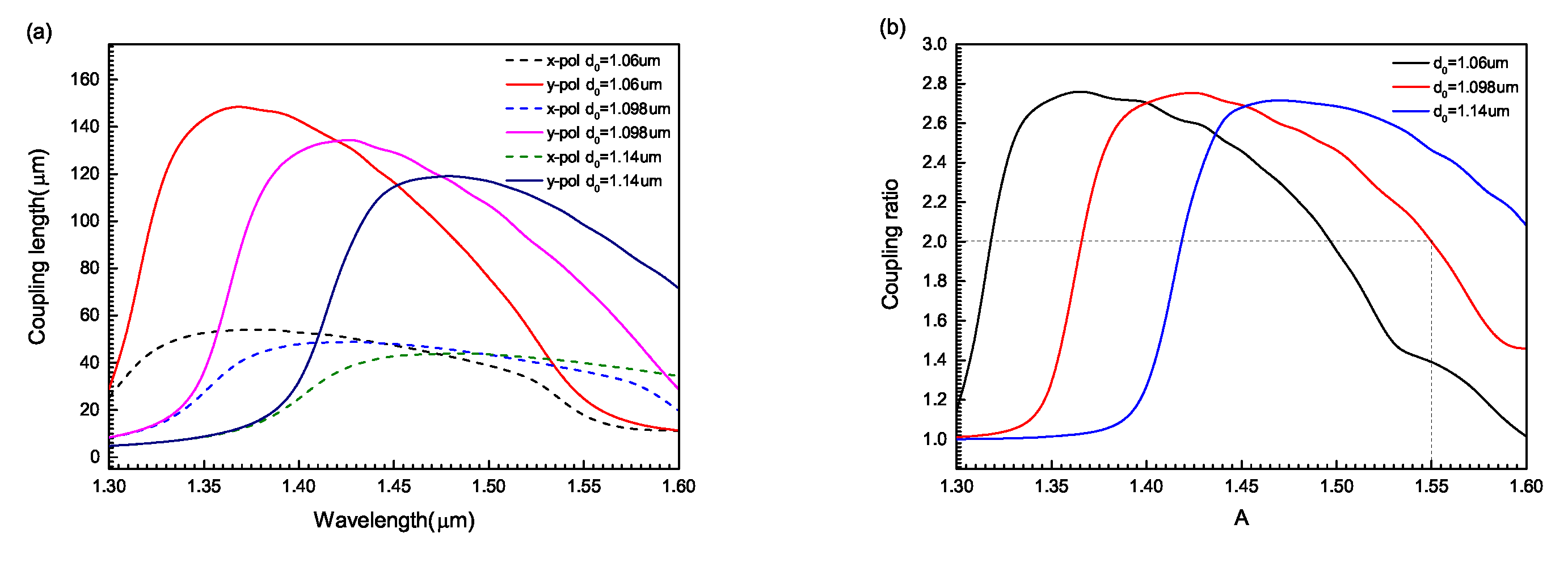
By filling the high refractive index chalcogenide glass
into the center hole of the double-core PCF, the birefringence characteristics of the x- and y-polarization modes are changed, which leads to the change of the coupling length in the x- and y-polarized directions. When the diameter of cladding pores is 1.2
m, as the
core diameter increases from 1.06 to 1.14
m, the changes in the coupling length and coupling ratio of the circular double-core PCF are shown in
Figure 7. From
Figure 7a, when the wavelength increases from 1.30 to 1.60
m, the coupling length of the circular PCF first increases and then decreases. For the same wavelength, the coupling length decreases with the increase of chalcogenide glass
diameter at short wavelength, while increases with the increase of chalcogenide glass
diameter at long wavelength. This shows that at short wavelengths, the larger the diameter of chalcogenide glass, the greater the refractive index difference between the odd mode and the even mode, and the easier it is for the optical field energy to couple from one core to another. At long wavelengths, the smaller the diameter of chalcogenide glass, the easier it is for the light field energy to couple from one core to another. From
Figure 7b, as the wavelength increases from 1.30 to 1.60
m, the coupling ratio of different chalcogenide glass diameters increases first and then decreases. For the same wavelength, as the diameter of the chalcogenide glass increases, the coupling ratio gradually decreases at short wavelengths, while it gradually increases at long wavelengths. When the diameter of chalcogenide glass
is 1.098
m, the coupling ratio reaches the ideal value of 2 at the wavelength of 1.55
m. Hence, a two-core PCF polarization beam splitter can improve its beam splitting performance by adjusting the diameter of chalcogenide glass
.
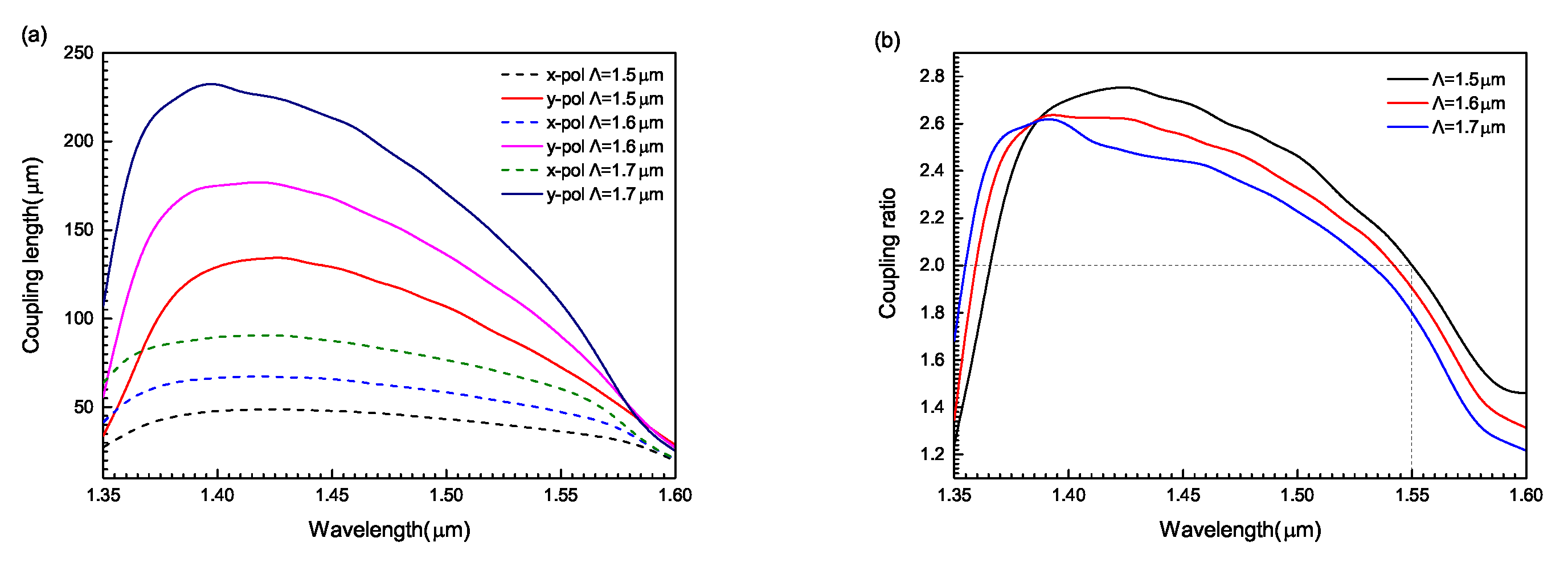
Adjusting the distance between adjacent air holes can change the asymmetry degree of the double-core PCF, and then change the birefringence, which leads to the change of the coupling length in x- and y-polarized directions. When the
core diameter is 1.098
m, as the adjacent pore spacing increases from 1.06 to 1.14
m, the evolution of the coupling length and coupling ratio of the circular double-core PCF with wavelength is shown in
Figure 8. From
Figure 8a, with the increase of wavelength from 1.35 to 1.60
m, the coupling lengths in x- and y-polarized directions first increase and then decrease. For the same wavelength, as the pore spacing decreases from 1.7 to 1.5
m, the PCF coupling length gradually decreases. This is mainly because the cladding pores around the core become tighter as the pore spacing decreases. The field energy is not easy to leak out, which makes it easier for the optical field energy to couple from one core to another, resulting in the decrease of coupling length. In addition, as the distance between adjacent pores decreases, the asymmetry of the structure around the core increases. This increases the birefringence, which in turn reduces the coupling length. From
Figure 8b, with the increase of wavelength, the coupling ratio first increases and then decreases. When the pore spacing increases from 1.5 to 1.7
m, the coupling ratio increases at short wavelength and decreases at long wavelength. In addition, when the pore spacing is 1.5
m, the coupling ratio can reach the ideal value of 2 at the wavelength of 1.55
m. Hence, the desired beam splitting performance can be obtained by adjusting the pore spacing.
Extinction Ratio (ER) is used to estimate the output power ratio of x- and y-polarized light in the fiber core, and it is the key parameter to measure the beam splitting performance of PCF polarization beam splitter. The higher the ER, the better the polarization beam splitting performance. The expression of ER is [
37]:
wherein
and
, respectively, represent the output power in the x- and y-polarized directions.
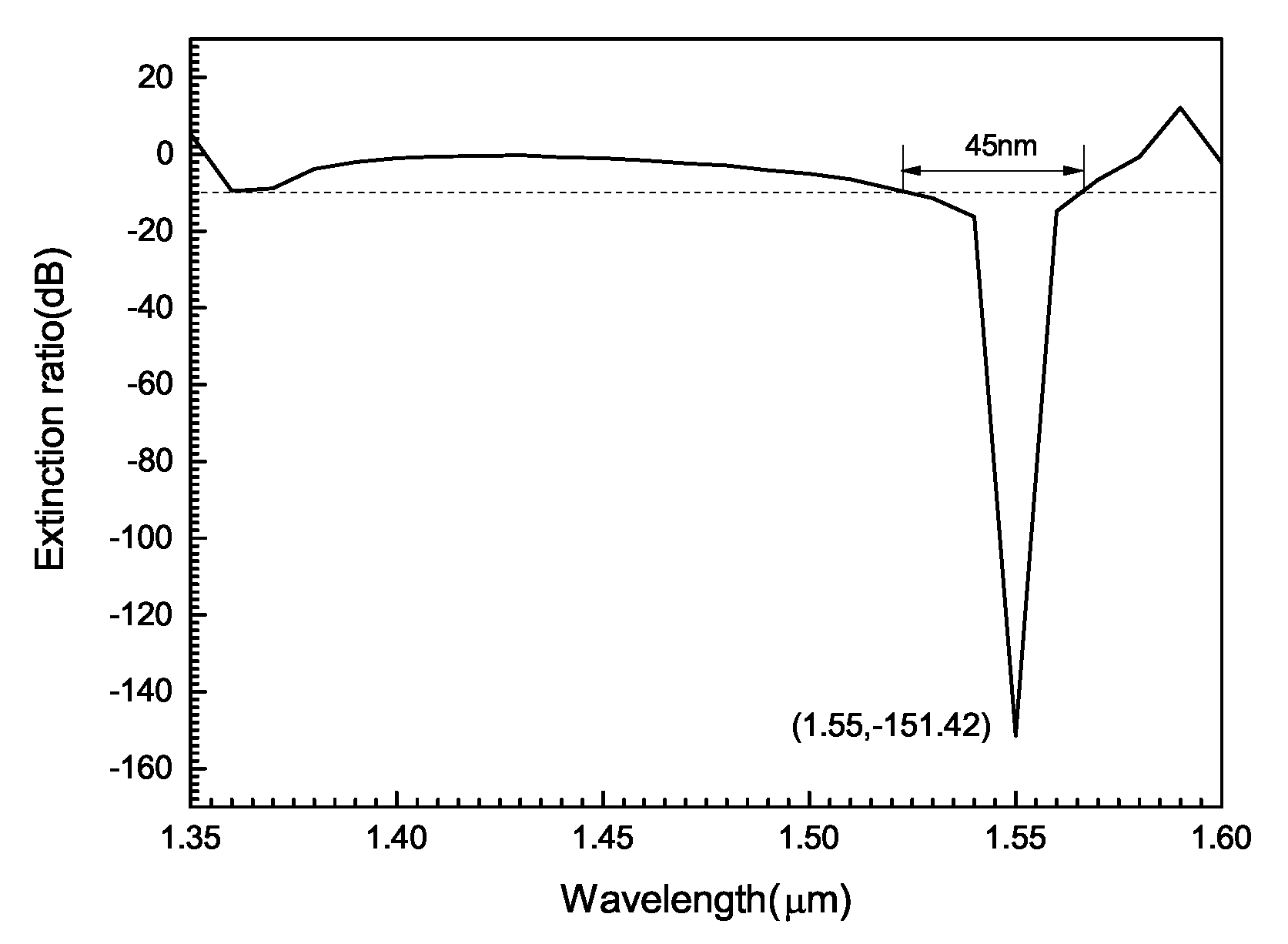
Figure 9 shows the evolution of the ER of the circular dual-core PCF with the operating wavelength. When the structure parameters are
m,
m,
m, the bandwidth of ER below −10 dB is 45 nm, and the maximum ER can reach −151.42 dB at the communication wavelength of 1.55
m. The high ER indicates that the output power of x-polarized light at the wavelength of 1550 nm is much greater than that of y-polarized light. In other words, there is only x-polarized light in the core, while y-polarized light is coupled into another core, so the circular double-core PCF filled with
has a good polarization beam splitting function at the wavelength of 1550 nm. Hence, PCF with this circular double-core structure can be well applied to the fabrication of optical beam splitting devices.
It can be seen from
Table 1 that the
of the previously reported PCF polarization beam splitter is mostly below 100 dB. The
of the
filled circular double-core PCF beam splitter designed in this paper reaches 151.42 dB, which is much higher than that reported in other documents. This shows that the beam splitter designed in this paper has better beam splitting function. In addition, the beam splitting length of the polarization beam splitter designed in this paper is 72.43
m, which is much shorter than that reported in other documents. Therefore, compared with the previously reported PCF beam splitter, the PCF beam splitter proposed in this paper has better performance.


