Communication

Adaptive Wave-Front Shaping and Beam Focusing through Fiber Bundles for High-Resolution Bioimaging

by
Matvey S. Pochechuev
1,
Ilya V. Fedotov
1,2,3,4,
Maxim A. Solotenkov
1,
Maria S. Andreeva
1,
Aleksandr A. Lanin
1,3,4,
Andrei B. Fedotov
1,3,4,5 and
Aleksei M. Zheltikov
1,2,3,4,*
1
Physics Department, International Laser Center, M.V. Lomonosov Moscow State University, 119992 Moscow, Russia
2
Department of Physics and Astronomy, Texas A&M University, College Station, TX 77843, USA
3
Advanced Photonics Group, Russian Quantum Center, 143025 Skolkovo, Russia
4
Laboratory of Guided-Wave Optics for Quantum Technologies, A.N. Tupolev Kazan National Research Technical University, 420126 Kazan, Russia
5
Advanced Photonics Group, National University of Science and Technology “MISiS”, 119049 Moscow, Russia
*
Author to whom correspondence should be addressed.
Photonics 2022, 9(1), 21; https://doi.org/10.3390/photonics9010021
Submission received: 27 October 2021 / Revised: 14 December 2021 / Accepted: 22 December 2021 / Published: 31 December 2021
(This article belongs to the Special Issue Topical Problems of Biophotonics)

Abstract

:
We demonstrate an adaptive wave-front shaping of optical beams transmitted through fiber bundles as a powerful resource for multisite, high-resolution bioimaging. With the phases of all the beamlets delivered through up to 6000 different fibers within the fiber bundle controlled individually, by means of a high-definition spatial light modulator, the overall beam transmitted through the fiber bundle can be focused into a beam waist with a diameter less than 1 μm within a targeted area in a biotissue, providing a diffraction-limited spatial resolution adequate for single-cell or even subcellular bioimaging. The field intensity in the adaptively-focused continuous-wave laser beam in our fiber-bundle-imaging setting is more than two orders of magnitude higher than the intensity of the speckle background. Once robust beam focusing was achieved with a suitable phase profile across the input face of the fiber bundle, the beam focus can be scanned over a targeted area with no need for a further adaptive search, by applying a physically intuitive, wave-front-tilting phase mask on the field of input beamlets. This method of beam-focus scanning promises imaging speeds compatible with the requirements of in vivo calcium imaging.

1. Introduction

While the capability of optical fibers to transfer images has been realized and demonstrated experimentally in the late 1920s [1,2], the concept of imaging via fiber bundles had to wait for several decades before fiber fabrication technologies and low-loss fiber materials became mature enough to support the creation of practical fiber imaging systems, paving the way for revolutionary breakthroughs in biophotonics [3]. Modern fiber-optic technologies provide powerful resources for the fabrication of specialty-design optical fibers [4,5,6,7,8] for complex imaging tasks and multichannel photometry [3,9,10,11,12,13,14], including dedicated fiber-bundle systems for high-resolution bioimaging [15,16,17], advanced fiber-optic neural interfaces [3,10,18,19,20], and high-precision fiber-optic biothermometers [21].
As a promising bioimaging modality, an integration of fiber bundles with gradient-index (GRIN) fiber lenses was shown to provide a platform for the creation of reconnectable implantable ultraslim fiber-optic microendoscopes [19], enabling simultaneous fluorescence imaging of individual cells in distinctly separate regions in the brain of freely moving rodent models, including brain structures as distant as the neocortex and hippocampus [20]. Expanding the horizons of bioimaging are the ideas of imaging through multimode waveguides. While the original proposals and first experimental demonstrations of this imaging modality date back to the 1960s and 1970s [22,23,24], it is the recent breakthroughs in adaptive optics combined with advanced approaches to image restoration that paved the way for the renaissance of these ideas, pushing the frontiers of fiber-optic endoscopy [25,26,27,28,29,30,31,32,33,34,35,36,37,38,39,40]. Extending this method to a fiber-bundle format would help widen the field of view and scale up the information capacity of fiber-based bioimaging systems, thus serving to close the gap between the capabilities of fiber-optic endoscopes and the demands of in vivo studies on complex biological systems, including brain imaging in awake, freely moving animal models.
Here, we show that such an extension is indeed possible. We present experiments that demonstrate an adaptive wave-front shaping of optical beams transmitted through fiber bundles as a powerful resource for multisite, high-resolution bioimaging. With the phases of all the beamlets delivered through different fibers within the fiber bundle controlled individually, by means of a high-definition spatial light modulator (SLM), the overall beam transmitted through the fiber bundle can be focused within a targeted area in a biotissue, providing a diffraction-limited spatial resolution adequate for single-cell or even subcellular bioimaging. Once robust beam focusing was achieved with a suitable phase profile across the input face of the fiber bundle, the beam focus can be scanned over a targeted area with no need for a further adaptive search, by applying a physically intuitive, wave-front-tilting phase mask on the field of input beamlets.

2. Imaging through Fiber Bundles

Experiments (Figure 1) were performed on various types of fiber bundles, each comprising N ≈ 1000 to N ≈ 6000 identical optical fibers whose diameters df ranged from ≈1.0 to ≈2.4 μm and whose centers were spaced at a mean distance Λ of ≈1.8 to ≈3 μm. Specifically, experiments with visible radiation were performed with N ≈ 1600 fiber bundles (Fujikura FIGH-016-160S or equivalent) and N ≈ 6000 fiber bundles (Fujikura FIGH-016-280S or equivalent). Experiments with near-infrared femtosecond laser pulses were carried out with N ≈ 6000 fiber bundles (Fujikura FIGH-06-400N or equivalent).
When used in a standard image-transmission modality, without adaptive beam shaping, such fiber bundles provided a spatial resolution within the Nyquist spatial sampling rate, aNΛ, as dictated by the structure of the fiber bundle. Shown in Figure 2 are typical images of fluorescent polystyrene beads with a diameter of ≈2 μm recorded through two segments of an identical N ≈ 1600 fiber bundle, connected to each other using the fiber-bundle connection techniques as described in detail elsewhere [18,20], with a bundle-to-bundle rotation angle α = 0 (Figure 2c), α ≈ 90° (Figure 2d), and α ≈ 180° (Figure 2e).

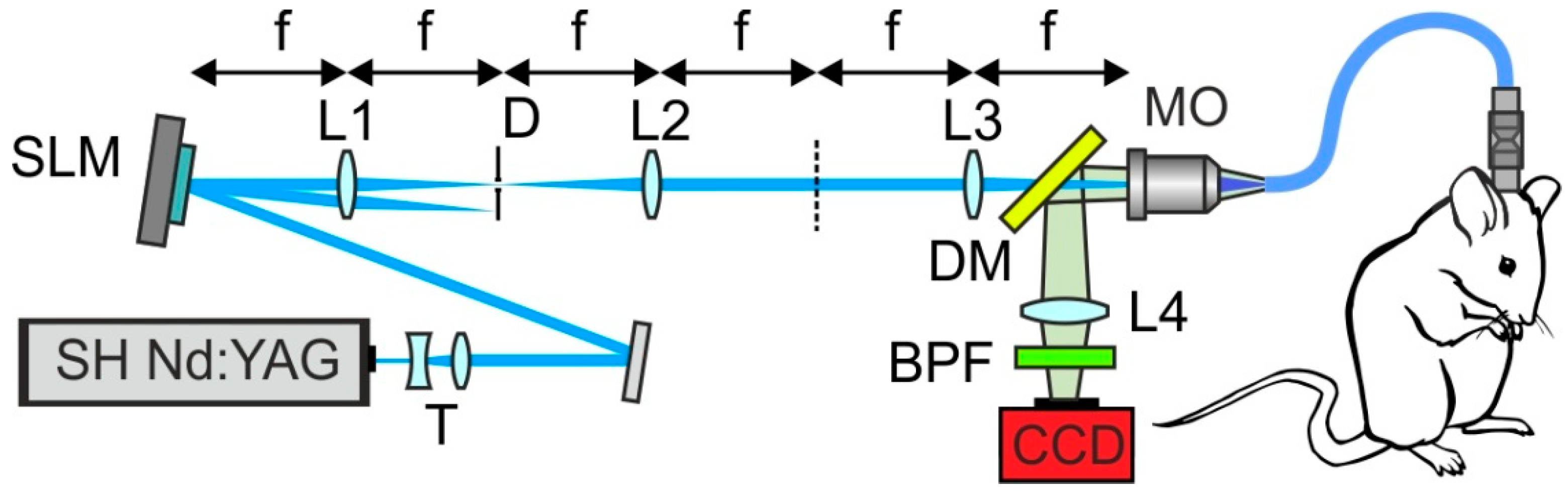
3. Adaptive Beam Shaping

For adaptive beam shaping, a visible or near-infrared laser beam–the 473-nm, 3-mW second-harmonic output of a continuous-wave Nd: YAG laser or the 1050-nm, 1-nJ, the 150-fs output of a mode-locked Nd: YAG laser–is expanded with an adjustable telescope (T in Figure 1) and is directed, with a system of mirrors, to a programmable liquid-crystal-on-silicon spatial light modulator (SLM in Figure 1). The pulse widths of ultrashort laser pulses are determined throughout this work based on autocorrelation traces and second-harmonic-generation-based frequency-resolved optical gating (FROG) (see Refs. [41,42,43] for details of bioimaging-oriented short-pulse characterization). As the laser beam gets reflected off the SLM, it acquires a spatial phase shift, which can be represented as an m1 × m2 matrix Φ = {φqp} (Figure 3), where m1 and m2 are the numbers of SLM pixels along respectively the x- and y-axes in the SLM plane and φqp is the tunable phase shift induced by an individual SLM pixel whose position (xq, yp) within the m1 × m2 array of SLM pixels is defined by its subscripts 1 ≤ qm1 and 1 ≤ pm2. For a typical SLM used in our experiments (PLUTO-2-NIR-011 or equivalent, operating within the range of wavelengths from ≈420 to 1100 nm), m1 = 1920 and m2 = 1080.
The beam produced via zeroth-order diffraction (ZOD) is removed with a suitably designed SLM–L1–D–L2 4f system (Figure 1), with lenses L1 and L2 positioned at z = f and z = 3f, respectively, and with a diaphragm D placed at z = 2f (Figure 1). With ZOD removed, the SLM-plane field distribution with the spatial phase Φ = {φqp} is re-imaged, with another 4f system and a microscope objective (MO1 in Figure 1) onto the input end of the fiber bundle (Figure 1 and Figure 3). The wave-front of the beam transmitted through the fiber bundle is shaped toward achieving a goal-function field-intensity distribution (r) within an object plane behind the fiber bundle via an adaptive, pixel-by-pixel control of the phase mask Φ = {φqp}, synthesized by the SLM and applied to the laser beam (Figure 3).

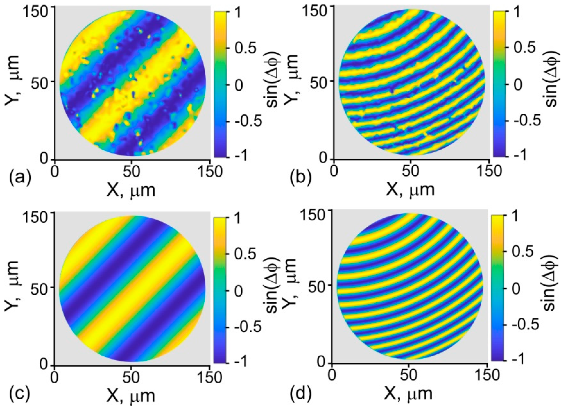
4. Phase-Mask Synthesis

The phase-mask synthesis by the SLM is guided by an iterative search, aimed at minimizing the discrepancy 𝒟(r) = (r) − 𝒢(r) between the goal-function field-intensity distribution (r) and the laser field-intensity distribution 𝒢(r) achieved in the object plane with a laser beam subject to a specific phase mask Φ and measured by imaging the field intensity profile in the object plane onto a high-sensitivity CCD camera with the use of a microscope objective and a lens (MO2 and L6 in Figure 1) distribution. With the field-intensity distribution 𝒢(r) given as an n1 × n2 array of readouts from individual pixels within the CCD camera, both (r) and 𝒢(r), as well as their discrepancy 𝒟(r), are represented as n1 × n2 matrices, with r understood as the vector of coordinates of CCD pixels.
An iterative search for the optimal phase mask Φ0 can now be formalized as a search for Φ0 within the set of m1 × m2 phase-shift matrices {Φk} that minimizes the discrepancy 𝒟k(r) = (r) − 𝒢k(r) within the set of field-intensity distributions {𝒢k(r)}, with each 𝒢k(r) representing the matrix of CCD readouts on the object-plane field-intensity distribution achieved with a laser beam subject to a phase mask Φk. Such an iterative search is performed in our experiments by using a genetic algorithm [44,45,46]. Briefly, the iterative-search procedure implemented in this study starts with a random set of phase masks as the initial approximation (step 1 in Figure 4), analyzes beam profiles for all the phase masks in the current set as a basis for phase-mask selection (step 2 in Figure 4), keeps or rejects phase masks depending on how rapidly the measured beam profiles 𝒢k(r) converge to the goal function (r) (step 3 in Figure 4), employs the phase masks that survived the selection stage to synthesize phase masks of next-generation (step 4 in Figure 4), adds random mutations (step 5 in Figure 4), and repeats the entire process with the new set of phase masks.

5. Multiple-Beamlet Wave-Front Shaping

The number of pixels in the SLM used in our experiments, m1 × m2 > 2 × 10⁶, is sufficient to dedicate ≳400–2000 pixels to tailor the spatial phase within each of the fibers constituting a typical N ≈ 1000 to N ≈ 5000 fiber bundle. The beam behind the fiber bundle can be thus viewed as consisting of N beamlets with individually tailored phase profiles (Figure 3). Specifically, for a fiber bundle with N ≈ 1500, the working area of the SLM is divided into N ≈ 1500 clusters, each including 37 × 37 SLM pixels dedicated to phase-profile shaping across one of the fibers within the fiber bundle (Figure 3).

6. Adaptive Beam Focusing

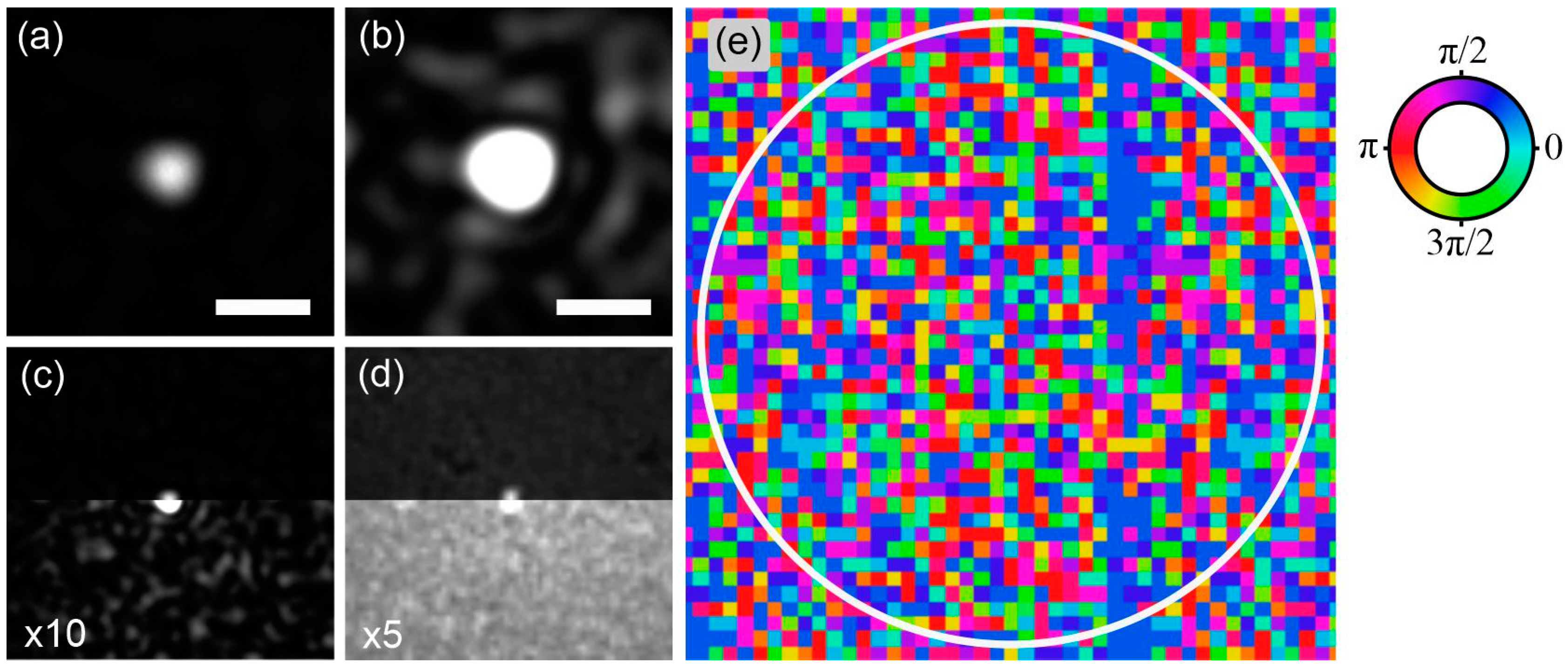
6.1. Field-Intensity Profiles

The images presented in Figure 5a–d visualize typical field intensity distributions in adaptively focused 473-nm continuous-wave and 150-fs, 1050-nm Yb laser beams in the object plane at a distance of ≈500 μm behind the rear end of the fiber bundle. For both laser outputs, beam focusing is performed via an adaptive search for an optimal phase mask Φ0 using an iterative procedure as described above. The phase mask Φ0 found via such an iterative search is presented in Figure 5e. Shown by color coding in this figure is the phase shift within the clusters of 24 × 24 SLM pixels dedicated to phase-profile shaping across one of the fibers–or one of the beamlets–within the fiber bundle (Figure 3). The working area of the SLM imaged onto the input end of the fiber bundles is shown by the white circle in Figure 5e. The phase mask is periodically tessellated outside this working area for a higher quality of the phase profile transferred to the input face of the fiber bundle.

6.2. Coherent-Peak-to-Speckle-Background Contrast

Well-resolved central peaks in field intensity distributions corresponding to adaptively focused laser beams (Figure 5a–d) are observed in our experiments against a background of laser speckles. To give a better idea of the contrast of the peak field intensity within the beam focus relative to the speckle-background intensity, unamplified beam images in Figure 5a, as well as in the upper parts of Figure 5c,d are presented alongside amplified images (Figure 5b and the lower parts in Figure 5c,d), which help visualize the speckle background in the beam-focus plane behind the fiber bundle.
For beam profiles as shown in Figure 5a,b, the ratio of the peak laser field intensity within the beam focus to the mean intensity of the speckle background is estimated at ≈110 for the cw 473-nm laser beam (Figure 5c) and at ≈15 for 150-fs, 1050-nm Yb-laser pulses (Figure 5d). That the ratio achieved for cw laser radiation is substantially higher than the ratio for ultrashort laser pulses is fully consistent with the key tendencies in the behavior of the number of spectral–temporal modes, whose coherent combining provides beam focusing [47]. Specifically, for laser pulses with a pulse width τ0, only the modes whose relative group delay behind the fiber bundle does not exceed τ0 can effectively contribute to the coherent peak of the laser field at the beam focus. The modes with larger group delays, reflecting both the intermodal and fiber-to-fiber dispersion, will fall outside the time window limited by τ0 and will not contribute to coherent combining leading to beam focusing.
As a typical dynamic of adaptive-search convergence to a stable beam focus, the readout tends to saturate, following the initial stage of almost linear growth with the number of iterations N, observed for our genetic algorithm for N ≤ 1000. For a standard liquid-crystal-on-silicon SLM with a frame-refresh rate of 180 Hz, adaptive beam-focusing optimization at ≈90% of is achieved within less than 1 min.

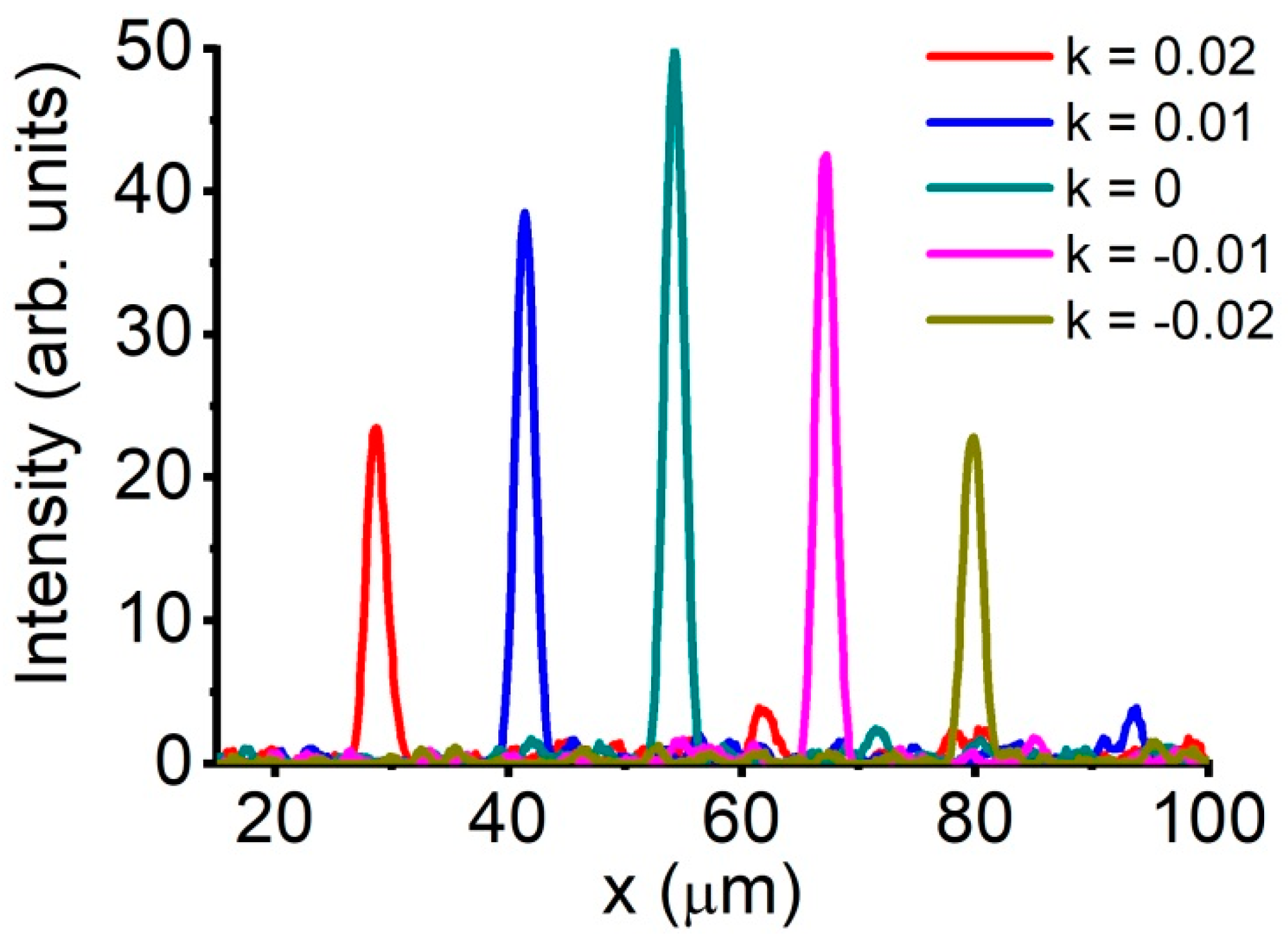
7. Fast Beam-Focus Scanning

Once robust beam focusing, such as the one illustrated in Figure 5a–d, was achieved with a suitable phase profile Φ0 across the input face of the fiber bundle (Figure 5e), the beam focus can be rapidly scanned over a targeted area with no need for a further adaptive search. This is achieved by adding a linear phase δ q p = q k x + p k y , with constant kx and ky, across the SLM that was already set to synthesize the optimal phase mask Φ0. As a useful physical insight, the phase δ q p is equivalent to wave-front tilting [48,49].
Presented in Figure 6 is the experimental demonstration of this method of fast beam-focus scanning. In this experiment, an adaptive search for an optimal phase profile is first performed to provide a robust focusing of a cw 473-nm laser beam behind a fiber bundle. Once such beam focusing was achieved, with a suitable phase mask Φ0, a linear phase δ q p with kx = k and ky = 0 is added to shift the beam focus along the x-axis. With k varied from k ≈ −0.02 to k ≈ 0.02, the beam focus is seen to shift by more than 50 μm without losing its robustness (Figure 6).
Since the beam focus can now be steered with no need to re-run the adaptive search, a frame rate of 𝒫 ≈ 1 frame per second can be achieved by using a standard, fg ≈ 16 kHz galvoscanning mirror to scan over a ≈ 0.4 × 0.4 mm2 field of view with a Nyquist-criterion spatial resolution σ ≈ 1 μm, as typically needed in bioimaging. A typical 0.1 × 0.1 mm2 field of view in calcium imaging, on the other hand, can be scanned with a frame rate of 𝒫 ≈ 16 frames per second.
Because a parabolic phase shift is known to translate into an axial shift of the adaptive beam focus [48,49], a suitable combination of linear and parabolic phases enables fast three-dimensional beam-focus scanning with no need to repeat an iterative search for each new (x, y, z) point within the entire range where adaptive beam focusing retains its robustness.

8. Toward New Bioimaging Modalities: Combining Adaptive Beam Shaping with Reconfigurable Fiber-Bundle-to-Fiber-Bundle Connection

Adaptive wave-front shaping and beam focusing through fiber bundles provide means to expand the capabilities of fiber-bundle bioimaging systems, opening routes toward truly 3D deep-brain imaging, as well as 3D-scanned optogenetic [9,10,50,51,52,53,54,55] and thermogenetic [56,57,58,59] stimulation of individual cells and cellular populations within strongly scattering, morphologically complex biological systems, including distributed neural and glial-cell networks. Central to the practical implementation of these approaches (Figure 7) is a technology of flexible and, wherever possible, reconfigurable fiber-bundle-to-fiber-bundle (FB2FB) connections used with both mode-locked and continuous-wave laser sources [10,11,12,13,14,15,16,17,18].
Currently available FB2FB platforms include FB2FB-reconnectable, implantable fiber-bundle endoscopes for minimally invasive in vivo brain imaging [18], as well as FB2FB-reconnectable, implantable ultraslim fiber-optic microendoscopes that integrate multiple fiber bundles with gradient-index fiber lenses [20], enabling a simultaneous fluorescence imaging of individual cells in distinctly separate deep brain regions. Representative examples of images transmitted through two reconnectable fiber bundles are shown in Figure 2.
While some of the in vivo studies are performed on immobilized animals [60], allowing fiber deformations and related phase shifts to be reduced to a minimum, thus making adaptive beam focusing easier to implement, other in vivo experiments only make sense if they are conducted with freely moving animal models [9,10,11,12,13,14,15,18,19,20,21,61]. Such in vivo studies pose numerous challenges to adaptive focusing through optical fibers. Specifically, fiber deformations, such as bending and twisting, are known to give rise to dynamic phase shifts, which often change too rapidly and too abruptly to be corrected via any conceivable adaptive search algorithm. As one remedy, a suitably tailored fiber structure, e.g., a twisted multicore fiber [37] or a fiber with a photonic-crystal cladding [21,62] can help stabilize fiber modes against bending- and twisting-induced perturbations.
Results of experiments presented in Figure 8a,b suggest, perhaps, a more versatile solution, showing that bending- and twisting-related phase shifts can be corrected via a careful holographic phase referencing. In these experiments, the long-coherence-length laser output is first beam-expanded and spatially filtered to mimic a plane wave, to be split into two beams with a beam splitter, yielding a probe and a reference beam in two arms of a carefully adjusted interferometer. The probe beam is then transmitted through a fiber bundle, acquiring a spatial phase, whose profile is retrieved from an interference pattern that the probe beam forms with a tilted reference beam.
Presented in Figure 8a,b are representative interference patterns observed when the fiber bundle is subject to a carefully gauged bending (Figure 8a) and twisting (Figure 8b). As an important finding, the fringes are seen to closely follow a physically transparent fit of sin(Δφ), with the phase Δφ given by a bilinear form of x and y, as dictated by the geometry and symmetry of fiber deformation. This fit is seen to be remarkably uniform across the entire fiber bundle, suggesting a strategy for a straightforward interferometry-based correction of bending- and twisting-induced phase shifts for adaptive focusing through fiber probes in in vivo studies with freely moving animals. The work toward developing new fiber-optic bioimaging modalities combining FB2FB-reconnectable beam-delivery systems with adaptive wave-front shaping and beam focusing through fiber bundles (Figure 7) is currently in progress.
That the phase Δφ is uniform across the entire fiber bundle indicates that the fiber-to-fiber cross-talk within the bundle is weak. A more detailed analysis reveals a detectable cross-talk in less than 4% of fibers in the bundle. For fiber bundles with such properties, the transfer function T can be characterized via measurements on a few representative fibers rather than on all the fibers in the bundle. The double-pass transfer function T2 is measured by using a reflected signal from reflection-coating-covered distal ends of the fibers selected for T2 characterization [39]. The single-pass transfer function T1 can be measured using an artificial guide star within a targeted object [63]. Analysis of T1 and T2 for the fiber bundles used in our experiments shows that the double-pass phase is, to a good approximation, twice the single-pass phase.

9. Conclusions

To summarize, we demonstrated an adaptive wave-front shaping of optical beams transmitted through fiber bundles as a powerful resource for multisite, high-resolution bioimaging. With the phases of all the beamlets delivered through different fibers within the fiber bundle controlled individually, by means of a high-definition spatial light modulator, the overall beam transmitted through the fiber bundle can be focused within a targeted area in a biotissue, providing a diffraction-limited spatial resolution adequate for single-cell or even subcellular bioimaging. Once robust beam focusing was achieved with a suitable phase profile across the input face of the fiber bundle, the beam focus can be scanned over a targeted area with no need for a further adaptive search, by applying a physically intuitive, wave-front-tilting phase mask on the field of input beamlets.

Author Contributions

Conceptualization, M.S.P., I.V.F., A.B.F., A.A.L. and A.M.Z.; methodology, M.S.P., I.V.F., M.A.S., M.S.A., A.B.F. and A.M.Z.; resources, A.A.L., A.B.F. and A.M.Z.; experiments, M.S.P. and I.V.F.; data analysis, M.S.P., I.V.F. and A.M.Z.; writing, M.S.P., I.V.F. and A.M.Z. All authors have read and agreed to the published version of the manuscript.

Funding

This research was supported in part by the Russian Foundation for Basic Research (projects Nos. 18-29-20031, 19-02-00473, 19-29-12062, 18-02-40025, 20-21-00131, 20-52-53046), the Russian Science Foundation (project 20-12-00088–ultrabroadband optical science), the Ministry of Science and Higher Education of the Russian Federation (grant № 075-15-2020-801), the Welch Foundation (grant A-1801-20180324), and the “Brain, Cognitive Systems, Artificial Intelligence” Scientific and Educational School at M.V. Lomonosov Moscow State University.

Data Availability Statement

The data that support the findings of this study are available from the corresponding author upon reasonable request.

Conflicts of Interest

The authors declare no conflict of interest.

References

  1. Hansell, C.W. Picture Transmission. US Patent 1751584, 25 March 1930. Available online: https://patents.google.com/patent/US1751584A/en (accessed on 1 December 2021).
  2. Lamm, H. Biegsame optische Geräte. Z. Instrum. 1930, 50, 579–581. [Google Scholar]
  3. Flusberg, B.A.; Cocker, E.D.; Piyawattanametha, W.; Jung, J.C.; Cheung, E.L.M.; Schnitzer, M.J. Fiber-Optic Fluorescence Imaging. Nat. Methods 2005, 2, 941–950. [Google Scholar] [CrossRef]
  4. Russell, P. Photonic Crystal Fibers. Science 2003, 299, 358–362. [Google Scholar] [CrossRef] [PubMed]
  5. Cregan, R.F.; Mangan, B.J.; Knight, J.C.; Birks, T.A.; Russell, P.S.J.; Roberts, P.J.; Allan, D.C. Single-Mode Photonic Band Gap Guidance of Light in Air. Science 1999, 285, 1537–1539. [Google Scholar] [CrossRef] [PubMed] [Green Version]
  6. Smith, C.M.; Venkataraman, N.; Gallagher, M.T.; Müller, D.; West, J.A.; Borrelli, N.F.; Allan, D.C.; Koch, K.W. Low-Loss Hollow-Core Silica/Air Photonic Bandgap Fibre. Nature 2003, 424, 657–659. [Google Scholar] [CrossRef] [PubMed]
  7. Zheltikov, A.M. Holey Fibers. Phys.-Uspekhi 2000, 43, 1125–1136. [Google Scholar] [CrossRef]
  8. Zheltikov, A.M. Optical Devices: The Friendly Gas Phase. Nat. Mater 2005, 4, 267–268. [Google Scholar] [CrossRef]
  9. Stuber, G.D.; Sparta, D.R.; Stamatakis, A.M.; van Leeuwen, W.A.; Hardjoprajitno, J.E.; Cho, S.; Tye, K.M.; Kempadoo, K.A.; Zhang, F.; Deisseroth, K.; et al. Excitatory Transmission from the Amygdala to Nucleus Accumbens Facilitates Reward Seeking. Nature 2011, 475, 377–380. [Google Scholar] [CrossRef]
  10. Warden, M.R.; Cardin, J.A.; Deisseroth, K. Optical Neural Interfaces. Annu. Rev. Biomed. Eng. 2014, 16, 103–129. [Google Scholar] [CrossRef] [Green Version]
  11. Doronina-Amitonova, L.V.; Fedotov, I.V.; Fedotov, A.B.; Anokhin, K.V.; Zheltikov, A.M. Neurophotonics: Optical Methods to Study and Control the Brain. Phys.-Uspekhi 2015, 58, 345. [Google Scholar] [CrossRef]
  12. Doronina-Amitonova, L.V.; Fedotov, I.V.; Ivashkina, O.I.; Zots, M.A.; Fedotov, A.B.; Anokhin, K.V.; Zheltikov, A.M. Implantable Fiber-Optic Interface for Parallel Multisite Long-Term Optical Dynamic Brain Interrogation in Freely Moving Mice. Sci. Rep. 2013, 3, 3265. [Google Scholar] [CrossRef] [PubMed] [Green Version]
  13. Kim, C.K.; Yang, S.J.; Pichamoorthy, N.; Young, N.P.; Kauvar, I.; Jennings, J.H.; Lerner, T.N.; Berndt, A.; Lee, S.Y.; Ramakrishnan, C.; et al. Simultaneous Fast Measurement of Circuit Dynamics at Multiple Sites across the Mammalian Brain. Nat. Methods 2016, 13, 325–328. [Google Scholar] [CrossRef]
  14. Sych, Y.; Chernysheva, M.; Sumanovski, L.T.; Helmchen, F. High-Density Multi-Fiber Photometry for Studying Large-Scale Brain Circuit Dynamics. Nat. Methods 2019, 16, 553–560. [Google Scholar] [CrossRef] [PubMed] [Green Version]
  15. Vincent, P.; Maskos, U.; Charvet, I.; Bourgeais, L.; Stoppini, L.; Leresche, N.; Changeux, J.-P.; Lambert, R.; Meda, P.; Paupardin-Tritsch, D. Live Imaging of Neural Structure and Function by Fibred Fluorescence Microscopy. EMBO Rep. 2006, 7, 1154–1161. [Google Scholar] [CrossRef] [Green Version]
  16. Doronina-Amitonova, L.V.; Fedotov, I.V.; Efimova, O.; Chernysheva, M.; Fedotov, A.B.; Anokhin, K.V.; Zheltikov, A.M. Multicolor In Vivo Brain Imaging with a Microscope-Coupled Fiber-Bundle Microprobe. Appl. Phys. Lett. 2012, 101, 233702. [Google Scholar] [CrossRef]
  17. Doronina-Amitonova, L.V.; Fedotov, I.V.; Ivashkina, O.I.; Zots, M.A.; Fedotov, A.B.; Anokhin, K.V.; Zheltikov, A.M. Fiber-Optic Raman Sensing of Cell Proliferation Probes and Molecular Vibrations: Brain-Imaging Perspective. Appl. Phys. Lett. 2012, 101, 113701. [Google Scholar] [CrossRef] [Green Version]
  18. Pochechuev, M.S.; Fedotov, I.V.; Ivashkina, O.I.; Roshchina, M.A.; Meshchankin, D.V.; Sidorov-Biryukov, D.A.; Fedotov, A.B.; Anokhin, K.V.; Zheltikov, A.M. Reconnectable Fiberscopes for Chronic in Vivo Deep-Brain Imaging. J. Biophotonics 2018, 11, e201700106. [Google Scholar] [CrossRef]
  19. Pochechuev, M.S.; Fedotov, I.V.; Zheltikov, A.M. An Ultraslim All-Fiber Microendoscope for Depth-Resolved Imaging. Appl. Phys. Lett. 2018, 113, 191102. [Google Scholar] [CrossRef]
  20. Pochechuev, M.S.; Solotenkov, M.A.; Fedotov, I.V.; Ivashkina, O.I.; Anokhin, K.V.; Zheltikov, A.M. Multisite Cell- and Neural-dynamics-resolving Deep Brain Imaging in Freely Moving Mice with Implanted Reconnectable Fiber Bundles. J. Biophotonics 2020, 13, e202000081. [Google Scholar] [CrossRef]
  21. Fedotov, I.V.; Solotenkov, M.A.; Pochechuev, M.S.; Ivashkina, O.I.; Kilin, S.Y.; Anokhin, K.V.; Zheltikov, A.M. All-Optical Brain Thermometry in Freely Moving Animals. ACS Photonics 2020, 7, 3353–3360. [Google Scholar] [CrossRef]
  22. Spitz, E.; Wertz, A. Transmission des images a travers une fibre optique. Comptes Rendus Hebd. Seances Acad. Sci. Ser. B 1967, 264, 1015–1018. [Google Scholar]
  23. Yariv, A. Three-dimensional Pictorial Transmission in Optical Fibers. Appl. Phys. Lett. 1976, 28, 88–89. [Google Scholar] [CrossRef] [Green Version]
  24. Yariv, A. On Transmission and Recovery of Three-Dimensional Image Information in Optical Waveguides. J. Opt. Soc. Am. 1976, 66, 301–306. [Google Scholar] [CrossRef] [Green Version]
  25. Čižmár, T.; Dholakia, K. Shaping the Light Transmission through a Multimode Optical Fibre: Complex Transformation Analysis and Applications in Biophotonics. Opt. Express 2011, 19, 18871–18884. [Google Scholar] [CrossRef] [PubMed] [Green Version]
  26. Čižmár, T.; Dholakia, K. Exploiting Multimode Waveguides for Pure Fibre-Based Imaging. Nat. Commun. 2012, 3, 1027. [Google Scholar] [CrossRef] [Green Version]
  27. Papadopoulos, I.N.; Farahi, S.; Moser, C.; Psaltis, D. Focusing and Scanning Light through a Multimode Optical Fiber Using Digital Phase Conjugation. Opt. Express 2012, 20, 10583–10590. [Google Scholar] [CrossRef] [PubMed]
  28. Choi, Y.; Yoon, C.; Kim, M.; Yang, T.D.; Fang-Yen, C.; Dasari, R.R.; Lee, K.J.; Choi, W. Scanner-Free and Wide-Field Endoscopic Imaging by Using a Single Multimode Optical Fiber. Phys. Rev. Lett. 2012, 109, 203901. [Google Scholar] [CrossRef]
  29. Papadopoulos, I.N.; Farahi, S.; Moser, C.; Psaltis, D. High-Resolution, Lensless Endoscope Based on Digital Scanning through a Multimode Optical Fiber. Biomed. Opt. Express 2013, 4, 260–270. [Google Scholar] [CrossRef] [PubMed] [Green Version]
  30. Plöschner, M.; Tyc, T.; Čižmár, T. Seeing through Chaos in Multimode Fibres. Nat. Photonics 2015, 9, 529–535. [Google Scholar] [CrossRef]
  31. Andresen, E.R.; Bouwmans, G.; Monneret, S.; Rigneault, H. Two-Photon Lensless Endoscope. Opt. Express 2013, 21, 20713–20721. [Google Scholar] [CrossRef] [PubMed]
  32. Andresen, E.R.; Bouwmans, G.; Monneret, S.; Rigneault, H. Toward Endoscopes with No Distal Optics: Video-Rate Scanning Microscopy through a Fiber Bundle. Opt. Lett. 2013, 38, 609–611. [Google Scholar] [CrossRef] [PubMed]
  33. Tsvirkun, V.; Sivankutty, S.; Bouwmans, G.; Vanvincq, O.; Andresen, E.R.; Rigneault, H. Bending-Induced Inter-Core Group Delays in Multicore Fibers. Opt. Express 2017, 25, 31863–31875. [Google Scholar] [CrossRef] [PubMed] [Green Version]
  34. Warren, S.C.; Kim, Y.; Stone, J.M.; Mitchell, C.; Knight, J.C.; Neil, M.A.A.; Paterson, C.; French, P.M.W.; Dunsby, C. Adaptive Multiphoton Endomicroscopy through a Dynamically Deformed Multicore Optical Fiber Using Proximal Detection. Opt. Express 2016, 24, 21474–21484. [Google Scholar] [CrossRef]
  35. Sivankutty, S.; Tsvirkun, V.; Bouwmans, G.; Kogan, D.; Oron, D.; Andresen, E.R.; Rigneault, H. Extended Field-of-View in a Lensless Endoscope Using an Aperiodic Multicore Fiber. Opt. Lett. 2016, 41, 3531–3534. [Google Scholar] [CrossRef] [Green Version]
  36. Sivankutty, S.; Tsvirkun, V.; Vanvincq, O.; Bouwmans, G.; Andresen, E.R.; Rigneault, H. Nonlinear Imaging through a Fermat’s Golden Spiral Multicore Fiber. Opt. Lett. 2018, 43, 3638–3641. [Google Scholar] [CrossRef] [Green Version]
  37. Tsvirkun, V.; Sivankutty, S.; Baudelle, K.; Habert, R.; Bouwmans, G.; Vanvincq, O.; Andresen, E.R.; Rigneault, H. Flexible Lensless Endoscope with a Conformationally Invariant Multi-Core Fiber. Optica 2019, 6, 1185–1189. [Google Scholar] [CrossRef] [Green Version]
  38. Tsvirkun, V.; Sivankutty, S.; Bouwmans, G.; Katz, O.; Andresen, E.R.; Rigneault, H. Widefield Lensless Endoscopy with a Multicore Fiber. Opt. Lett. 2016, 41, 4771–4774. [Google Scholar] [CrossRef] [Green Version]
  39. Scharf, E.; Dremel, J.; Kuschmierz, R.; Czarske, J. Video-Rate Lensless Endoscope with Self-Calibration Using Wavefront Shaping. Opt. Lett. 2020, 45, 3629–3632. [Google Scholar] [CrossRef]
  40. Weiss, U.; Katz, O. Two-Photon Lensless Micro-Endoscopy with in-Situ Wavefront Correction. Opt. Express 2018, 26, 28808–28817. [Google Scholar] [CrossRef] [PubMed] [Green Version]
  41. Pochechuev, M.S.; Lanin, A.A.; Kelmanson, I.V.; Bilan, D.S.; Kotova, D.A.; Chebotarev, A.S.; Tarabykin, V.; Fedotov, A.B.; Belousov, V.V.; Zheltikov, A.M. Stain-Free Subcellular-Resolution Astrocyte Imaging Using Third-Harmonic Generation. Opt. Lett. 2019, 44, 3166–3169. [Google Scholar] [CrossRef]
  42. Lanin, A.A.; Pochechuev, M.S.; Chebotarev, A.S.; Kelmanson, I.V.; Bilan, D.S.; Kotova, D.A.; Tarabykin, V.S.; Ivanov, A.A.; Fedotov, A.B.; Belousov, V.V.; et al. Cell-Specific Three-Photon-Fluorescence Brain Imaging: Neurons, Astrocytes, and Gliovascular Interfaces. Opt. Lett. 2020, 45, 836. [Google Scholar] [CrossRef]
  43. Pochechuev, M.S.; Lanin, A.A.; Lanin, A.A.; Kelmanson, I.V.; Chebotarev, A.S.; Fetisova, E.S.; Bilan, D.S.; Shevchenko, E.K.; Ivanov, A.A.; Fedotov, A.B.; et al. Multimodal Nonlinear-Optical Imaging of Nucleoli. Opt. Lett. 2021, 46, 3608–3611. [Google Scholar] [CrossRef] [PubMed]
  44. Haupt, R.L.; Haupt, S.E. Practical Genetic Algorithms, 2nd ed.; John Wiley: Hoboken, NJ, USA, 2004. [Google Scholar]
  45. Musin, R.R.; Zheltikov, A.M. Designing Dispersion-Compensating Photonic-Crystal Fibers Using a Genetic Algorithm. Opt. Commun. 2008, 281, 567–572. [Google Scholar] [CrossRef]
  46. Conkey, D.B.; Brown, A.N.; Caravaca-Aguirre, A.M.; Piestun, R. Genetic Algorithm Optimization for Focusing through Turbid Media in Noisy Environments. Opt. Express 2012, 20, 4840–4849. [Google Scholar] [CrossRef]
  47. Mosk, A.P.; Lagendijk, A.; Lerosey, G.; Fink, M. Controlling Waves in Space and Time for Imaging and Focusing in Complex Media. Nat. Photonics 2012, 6, 283–292. [Google Scholar] [CrossRef] [Green Version]
  48. Freund, I.; Rosenbluh, M.; Feng, S. Memory Effects in Propagation of Optical Waves through Disordered Media. Phys. Rev. Lett. 1988, 61, 2328–2331. [Google Scholar] [CrossRef] [PubMed]
  49. Stasio, N.; Conkey, D.B.; Moser, C.; Psaltis, D. Light Control in a Multicore Fiber Using the Memory Effect. Opt. Express 2015, 23, 30532–30544. [Google Scholar] [CrossRef]
  50. Boyden, E.S.; Zhang, F.; Bamberg, E.; Nagel, G.; Deisseroth, K. Millisecond-Timescale, Genetically Targeted Optical Control of Neural Activity. Nat. Neurosci. 2005, 8, 1263–1268. [Google Scholar] [CrossRef]
  51. Diester, I.; Kaufman, M.T.; Mogri, M.; Pashaie, R.; Goo, W.; Yizhar, O.; Ramakrishnan, C.; Deisseroth, K.; Shenoy, K.V. An Optogenetic Toolbox Designed for Primates. Nat. Neurosci. 2011, 14, 387–397. [Google Scholar] [CrossRef] [Green Version]
  52. Deisseroth, K. Optogenetics. Nat. Methods 2011, 8, 26–29. [Google Scholar] [CrossRef]
  53. Miesenböck, G. The Optogenetic Catechism. Science 2009, 326, 395–399. [Google Scholar] [CrossRef] [PubMed]
  54. Deisseroth, K. Optogenetics: 10 Years of Microbial Opsins in Neuroscience. Nat. Neurosci. 2015, 18, 1213–1225. [Google Scholar] [CrossRef] [PubMed] [Green Version]
  55. Kim, C.K.; Adhikari, A.; Deisseroth, K. Integration of Optogenetics with Complementary Methodologies in Systems Neuroscience. Nat. Rev. Neurosci. 2017, 18, 222–235. [Google Scholar] [CrossRef]
  56. Fedotov, I.V.; Safronov, N.A.; Ermakova, Y.G.; Matlashov, M.E.; Sidorov-Biryukov, D.A.; Fedotov, A.B.; Belousov, V.V.; Zheltikov, A.M. Fiber-Optic Control and Thermometry of Single-Cell Thermosensation Logic. Sci. Rep. 2015, 5, 15737. [Google Scholar] [CrossRef] [Green Version]
  57. Lanin, A.A.; Fedotov, I.V.; Ermakova, Y.G.; Sidorov-Biryukov, D.A.; Fedotov, A.B.; Hemmer, P.; Belousov, V.V.; Zheltikov, A.M. Fiber-Optic Electron-Spin-Resonance Thermometry of Single Laser-Activated Neurons. Opt. Lett. 2016, 41, 5563. [Google Scholar] [CrossRef]
  58. Ermakova, Y.G.; Lanin, A.A.; Fedotov, I.V.; Roshchin, M.; Kelmanson, I.V.; Kulik, D.; Bogdanova, Y.A.; Shokhina, A.G.; Bilan, D.S.; Staroverov, D.B.; et al. Thermogenetic Neurostimulation with Single-Cell Resolution. Nat. Commun. 2017, 8, 15362. [Google Scholar] [CrossRef] [PubMed] [Green Version]
  59. Ermakova, Y.G.; Roshchin, M.V.; Lanin, A.A.; Balaban, P.M.; Zheltikov, A.M.; Belousov, V.V.; Nikitin, E.S. Thermogenetics as a New Direction in Controlling the Activity of Neural Networks. Neurosci. Behav. Phys. 2020, 50, 1018–1023. [Google Scholar] [CrossRef]
  60. Kelmanson, I.V.; Shokhina, A.G.; Kotova, D.A.; Pochechuev, M.S.; Ivanova, A.D.; Kostyuk, A.I.; Panova, A.S.; Borodinova, A.A.; Solotenkov, M.A.; Stepanov, E.A.; et al. In Vivo Dynamics of Acidosis and Oxidative Stress in the Acute Phase of an Ischemic Stroke in a Rodent Model. Redox Biol. 2021, 48, 102178. [Google Scholar] [CrossRef]
  61. Fedotov, I.V.; Ivashkina, O.I.; Pochechuev, M.S.; Roshchina, M.A.; Toropova, K.A.; Fedotov, A.B.; Anokhin, K.V.; Zheltikov, A.M. Quantitative Cognitive-Test Characterization of Reconnectable Implantable Fiber-Optic Neurointerfaces for Optogenetic Neurostimulation. J. Biophotonics 2017, 10, 1485–1491. [Google Scholar] [CrossRef] [PubMed]
  62. Zheltikov, A. Optical beam shift as a vectorial pointer of curved-path geodesics: An evolution-operator perspective. Opt. Express 2020, 28, 12302–12310. [Google Scholar] [CrossRef] [PubMed]
  63. Horstmeyer, R.; Ruan, H.; Yang, C. Guidestar-assisted wavefront-shaping methods for focusing light into biological tissue. Nat. Photonics 2015, 9, 563–571. [Google Scholar] [CrossRef] [PubMed] [Green Version]
Figure 1. Adaptive wave-front shaping and beam focusing through a fiber bundle: T, telescope; SLM, spatial light modulator; L1–L6, lenses; D, diaphragm; DM, dichroic mirror; FM, flip mirror; CCD, CCD camera; MO1, MO2, microscope objectives; FB, fiber bundle; BPF, bandpass filter.
Photonics 09 00021 g001
Figure 2. (a) The field intensity profile across a representative image of a group of fluorescent polystyrene beads recorded through two segments of an identical fiber bundle decomposed into the intensity profiles of images of individual beads, with four typical images of such beads shown on the right (the scale bar is 7 µm). (b) Wide-field microscope image of fluorescent polystyrene beads at the distal end of a 60-cm-long fiber bundle. (c,d) Typical images of these beads recorded through two 30-cm segments of an identical fiber bundle, connected to each other with a bundle-to-bundle rotation angle α = 0 (c), α ≈ 120° (d), and α ≈ 260° (e).
Photonics 09 00021 g002
Figure 3. Adaptive phase-front shaping of a laser beam at the input of a fiber bundle via reflection off a programmed spatial light modulator (SLM). Shown in the lower panel is the spatial phase mask applied to the reflected laser beam, represented as a matrix Φ = {φqp}, with φqp (coded with color) being the tunable phase shifts induced by individual SLM pixels. The working area of the SLM imaged onto the input end of the fiber bundles is shown by the black circle. Shown in the center of the lower panel is a blowup of the area enclosed with the white box at the center of the SLM, with individual SLM pixels within each cluster of pixels shown on the right.
Photonics 09 00021 g003
Figure 4. Genetic-algorithm search for the optimal phase mask for laser beam focusing through a fiber bundle. The process starts with a random set of phase masks as the initial approximation (step 1), analyzes beam profiles for all the phase masks in the current set as a basis for phase-mask selection (step 2), keeps or rejects phase masks depending on how rapidly the measured beam profiles converge to the goal function aimed at beam focusing (step 3), employs the phase masks that survived the selection stage to synthesize phase masks of next-generation (step 4), adds random mutations (step 5 in Figure 4), and repeats the entire process with the new set of phase masks.
Photonics 09 00021 g004
Figure 5. (ad) Images visualizing typical field intensity distributions in adaptively focused laser beams at a distance of ≈500 μm behind the fiber bundle with a length of ≈40 cm: (ac) 473-nm continuous-wave laser beam and (d) 150-fs, 1050-nm Yb-laser output. Unamplified images are shown in panel (a), as well as in the upper parts of panels (c,d). Panel (b) and the lower parts of panels (c,d) present amplified images with an amplification factor of 10 (b,c) and 5 (d). (e) The optimal phase mask Φ0 across the m1 × m2 = 1920 × 1080 SLM providing the field-intensity distribution with a high-contrast beam focus as shown in panels (a,b). Shown by color coding is the phase shift within the clusters of 24 × 24 SLM pixels dedicated to phase-profile shaping across one of the fibers within the fiber bundle. The working area of the SLM imaged onto the input end of the fiber bundles is shown by the white circle.
Photonics 09 00021 g005
Figure 6. Transverse shift of the beam focus of a 473-nm laser beam behind the 40-cm-long fiber bundle. The laser beam is first adaptively focused with a suitable phase profile Φ0 applied across the input face of the fiber bundle. Once robust beam focusing was achieved, a linear phase δqp = qkx + pky, with kx = k as specified in the plot and ky = 0 is added to the phase mask Φ0.
Photonics 09 00021 g006
Figure 7. Bioimaging with a multisegment reconnectable fiber bundle and adaptive beam focusing: SH Nd: YAG: Nd: YAG laser with second-harmonic output; SLM, spatial light modulator; L1–L4, lenses; D, diaphragm; CCD, CCD camera; DM, dichroic mirror; MO, microscope objective.
Photonics 09 00021 g007
Figure 8. Interference patterns that the probe beam transmitted through a 60-cm-long fiber bundle forms with a tilted reference beam: (a,b) experiments with the fiber bundle subject to (a) bending and (b) twisting and (c,d) the best sin(Δφ) fit, with Δφ = b1 + b2x + b3y + b42[(xx0)2 + (yy0)2] and (c) b1 = 2.8571 rad, b2 = 0.0665 μm−1, b3 = 0.0672 μm−1, b4 = 0, and (d) b1 = 2.55837 rad, b2 = 0.2547 μm−1, b3 = 0.4101 μm−1, b4 = 0.0397 μm−1.
Photonics 09 00021 g008
Publisher’s Note: MDPI stays neutral with regard to jurisdictional claims in published maps and institutional affiliations.

