1. Introduction
To protect metals or other matrix materials in industry, their surface is coated to achieve anti-rust, anti-oxidation and anti-corrosion properties. When the paint layer falls off or needs to be repainted for other reasons, the original paint layer must be thoroughly cleaned. Before the overhaul of a car body, it is necessary to remove the old paint from the surface of the body of a car to spray the new paint. There are various conventional cleaning methods for body paints, specifically mechanical and chemical methods. However, these methods are high cost, high-energy consumption and high pollution and easily damage the surface of the substrate, which cannot meet the environmental protection requirements of modern cleaning methods [
1,
2,
3,
4].
Therefore, many novel cleaning technologies have emerged, and, as one of the crucial methods, laser paint removal has gradually shown its advantages [
5]. S.D. Allen used an infrared pulsed laser to clean the surface of CaF
2, BaF
2 and NaCl and tested the water absorption of the material after cleaning. Compared with other cleaning methods, the target material after laser cleaning had a lower water absorption [
6].
Andrew C. Tam reported, in detail, the progress of using lasers to clean the surface contaminants of materials, for example, comparing the removal effects of liquid film assisted cleaning and dry laser cleaning [
7]. In addition, laser cleaning has been widely used in applications, including cultural relic restoration [
8,
9], particle removal [
10], the removal of carbon-containing sediment [
11] and rust removal [
12].
The first study on laser cleaning was conducted in 1969. Bedair et al. used a pulsed laser to remove an oxide layer on a nickel surface and first studied the damage threshold of the test sample [
13]. J.A.Fox first attempted paint removal. In 1974, Fox used a pulsed laser to remove single-layer black paint on an aluminum alloy and determined the optimal cleaning threshold [
14]. Thereafter, from the 1980s to the 1990s, researchers successively studied laser paint removal. In 1995, Katherine Liu et al. used two different lasers to test black paints on concrete blocks.
A detection spectrum was used to determine the removal depth and cleaning effect and the cleaning thresholds of CO
2 continuous laser and pulse Q-switched Nd:YAG were compared [
15]. In 1996, Akira Tsunemi and others used a CO
2 laser to clean the paint layer on the iron plate surface and used an optical microscope to measure the paint removal depth, analyzed the influence of the substrate surface condition on the paint removal effect and determined the best cleaning Threshold [
16]. In 1997, Shuichi Ashidate et al. used nanosecond pulsed lasers to remove paint on the surface of galvanized steel and determined the best cleaning threshold by measuring the removal depth [
17].
In 1998, Sp. G. Pantelakis et al. compared and analyzed the effect of an excimer laser and CO
2 laser cleaning epoxy primer on the surface of 2024 aluminum alloy and detected the residual stress of the target after cleaning [
18]. After the 21st century, Francois Brygo et al. studied the cleaning effect of a nanosecond pulsed Nd:YAG laser on single-layer gray epoxy paint, and they analyzed the cleaned samples using a surface profiler. It was established that the ablation thresholds of 100 ns and 5 ns pulse widths were significantly different [
19]. G. X. Chen et al. studied the effect of the power density of a CO
2 continuous laser on the removal of single-layer marine paints.
The cleaned samples were detected through Raman spectroscopy, and the optimal cleaning threshold was determined [
20]. Recently, D. M. D’ Addona et al. studied the effect of the energy density of a Q-switched Yb:YAG pulse laser on the removal of a pre-construction primer. After the experiment, the surface of the target was analyzed via imaging, and the percentage of energy size and cleaning area was obtained [
21]. I. Apostol et al. used the pulsed Nd:YAG to remove single-layer paint.
The relationship between ablation depth and energy density was measured using a contact rheometer and white light interferometer, and the change rule of the ablation depth was determined [
22]. H.C. Zhao et al. used a pulsed Nd:YAG to clean a single-layer polyacrylate-based coating on an aluminum alloy, and they explained the change in the chemical bond of the paint film during paint removal in detail by analyzing the sputter using a spectrometer [
23].
From the above literature, it was established that most studies used pulsed lasers, and there are few reports on the application of a continuous laser. For coating parameters, most of the studies only carried out a single coating experiment, but the paint-coating products did not have a single coating. According to the analysis results, most of the studies did not describe the change in temperature, removal depth and mechanism of action under multi-layer coating in detail. Therefore, an experimental study on laser cleaning of multi-layer coatings was carried out. Considering the painting system of the body of a car, the practitioners in the automobile manufacturing industry determined the coating types and parameters, and the paint layer on the surface of the car body was cleaned using a continuous fiber laser.
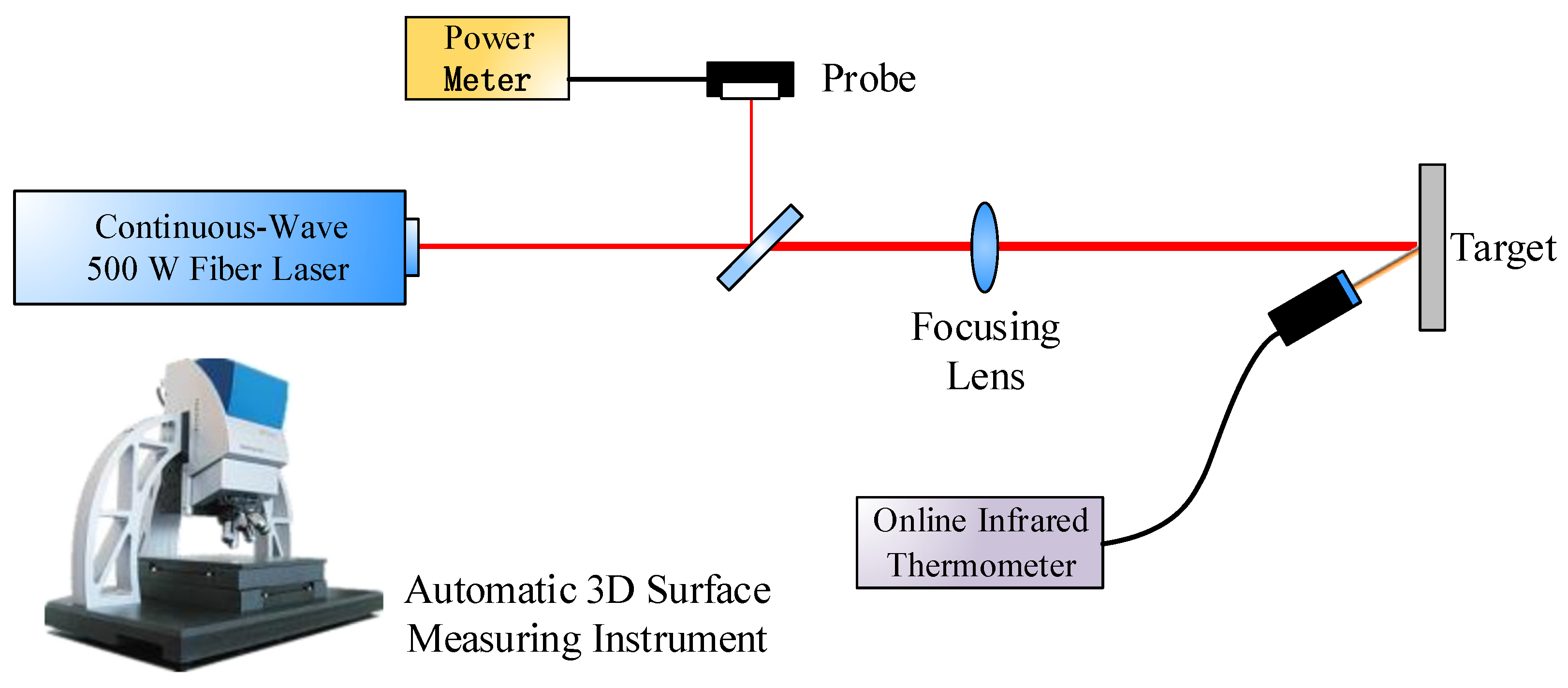
In this study, the effect of energy density on the coating removal depth was determined by the laser cleaning of multi-coatings on an aluminum alloy substrate. The surface morphology, removal depth and temperature change during the laser cleaning were observed. Through depth measurement of the samples after the experiment, it was established that the optimal cleaning threshold of the multi-layer coating was smaller than that of a single coating. The mechanism of laser cleaning of multilayer coatings was analyzed in depth. These results could provide feasible process parameters and process selection for the application of laser cleaning paints in automobiles and other industries, which is of great significance in engineering.
3. Experimental Results and Analysis
3.1. The Temperature Evolution and Cleaning Threshold of Epoxy Primer
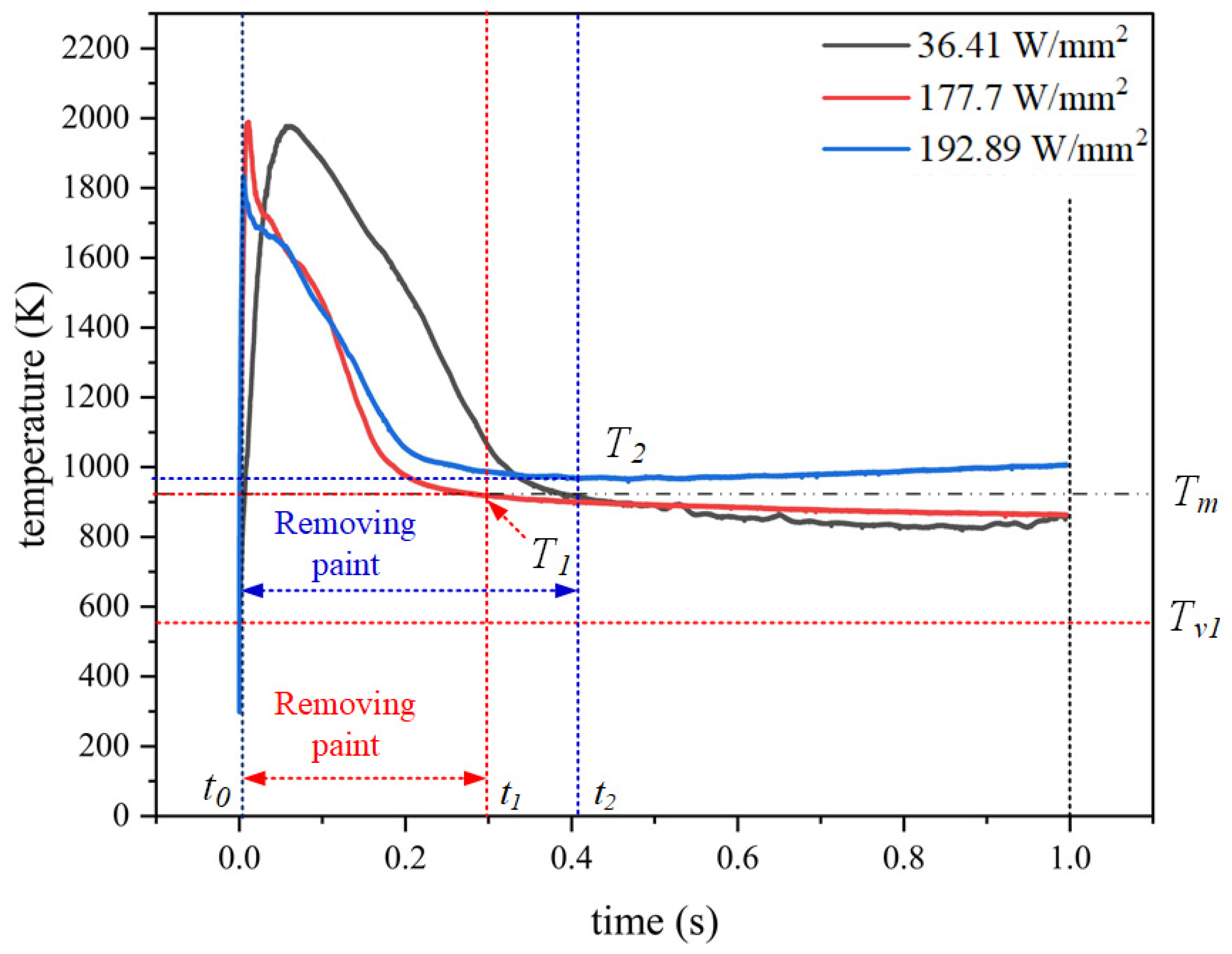
In
Figure 2, the vaporization point of epoxy primer is
Tv1 = 548.15 K, and the melting point of 7075 aluminum alloy is
Tm = 908.15 K. It is defined as
t0 when the temperature reaches the vaporization point of the paint layer.
For the cleaning of single epoxy primer coating, it can be seen from
Figure 2 that when the power density is 36.41 W/mm
2, the heating range is 0–0.06 s, when
t0 = 0.6 × 10
−5 s, the coating begins to remove, and the temperature is 573.75 K. The paint removal process (0–0.4 s) was relatively long. Due to the removal of paint, the temperature showed a downward trend, but the paint was not completely removed, and thus the temperature decreased slowly. At the later stage of 0.4–1 s, the temperature fluctuated and continued to decline, which was caused by the residual paint layer on the surface of the target and the heat dissipation of the aluminum alloy substrate.
When the power density reached 177.74 W/mm2, as shown in the figure, due to the increase of laser power, the heating interval was short 0–0.01 s. When t0 = 0.3 × 10⁻⁵ s, it reached the vaporization point Tv1 of the epoxy primer, and the temperature was 574.81 K. The paint layer was removed. The coating removal interval is t0 to t1. The coating removal leads to the mass migration of the paint layer, and the temperature begins to decrease rapidly.
When the paint decreases until it disappears, the laser directly acts on the aluminum alloy substrate, and the temperature drops to the melting point of the aluminum alloy when T1 (0.29 s, 908.12 K). The coating has been removed, and the temperature changes from a downward trend to a gentle. Currently, the temperature curve is the temperature of the laser acting on the aluminum alloy. Since the temperature is below the melting point of aluminum alloy, it is not enough to cause the phase transformation of the aluminum alloy, and thus matrix damage will not occur.
When the laser power density reaches the damage threshold of 192.89 W/mm2, the heating process (0–0.005 s) is shorter than that of 177.74 W/mm2, and the temperature at the moment of laser action (t0 ≤ 0.1 × 10⁻⁵ s) has exceeded the vaporization point Tv1. t0 to t2 are the coating removal interval, and the temperature decreases rapidly with the decrease of coating. When the temperature decreases to the lowest temperature T2 (0.41 s, 969.67 K), the paint completely disappears, and the laser directly acts on the aluminum alloy. Since then, the temperature continues to increase, because the laser power is too large, aluminum alloy melting occurs, which will lead to matrix damage.
When the laser power is concentrated on the surface of the paint, after the laser power is partially reflected and lost, a large amount of laser power is absorbed by the paint layer, causing the temperature in the paint layer to increase rapidly. When the temperature reaches or exceeds the vaporization point of the material, a phase change occurs, and thus the paint layer gradually disappears.
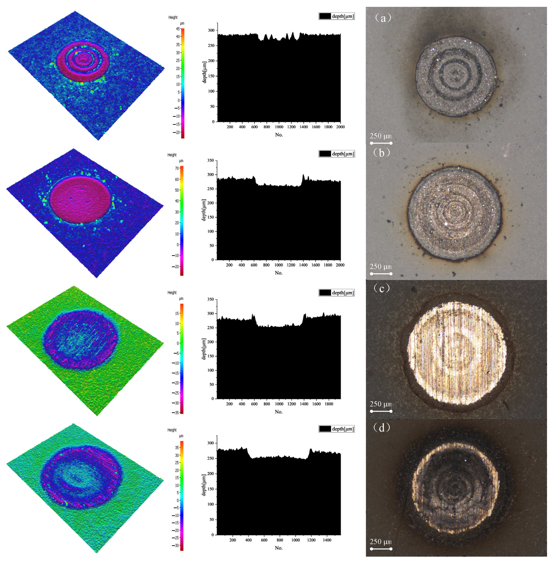
The paint film began to ablate when the power density was 36.41 W/mm
2, and the average ablation depth was 13.5675 μm after the automatic three-dimensional surface measurement (the surface morphology is illustrated in
Figure 3a). The cleaning was currently incomplete. Residual paints were still present on the surface, which improved the power density. During the experiment, a gas was obtained after the epoxy primer burns when the power density was 159.66 W/mm
2.
The surface of the paint burns and melts. After automatic three-dimensional inspection, we established that the surface of the paint film burned. The etching depth was 21.5090 μm (
Figure 3b), which reached the cleaning threshold, but the cleaning was incomplete. When working with a power density of 177.74 W/mm
2, the surface of the target emitted gas, black smoke, and the epoxy primer burned violently. The automatic three-dimensional surface measuring instrument established that the ablation depth of the paint film surface was 22.8944 μm (
Figure 3c), cleaning was completed, the cleaning effect was good, and no matrix damage was observed. The aluminum alloy matrix was damaged when the power density was 192.90 W/mm
2 (
Figure 3d). As the aluminum alloy expands after heating, the removal depth reduced to 19.0165 μm.
Surface observation of the cleaned sample showed that the cleaned target with a power density of 36.41 W/mm2 had a rougher surface, a thicker residual paint layer and a tight bond between the paint film and the substrate. The surface of the aluminum alloy could not be cleaned after blowing compressed air. After cleaning with 159.66 W/mm2, the residual paint layer on the surface of the sample was thin, the paint film was slightly separated from the substrate, and the smoothness of the cleaning area was poor.
Part of the substrate was exposed after blowing compressed air, but there was a residual paint layer. For the sample after cleaning with 177.74 W/mm
2, most of the paint film was separated from the substrate. A smooth, bright, complete and undamaged aluminum alloy substrate was exposed after blowing compressed air. No residual paint remained on the surface of the target after cleaning with 192.90 W/mm
2, the surface of the target was damaged, and the cleaning area had ablation marks.
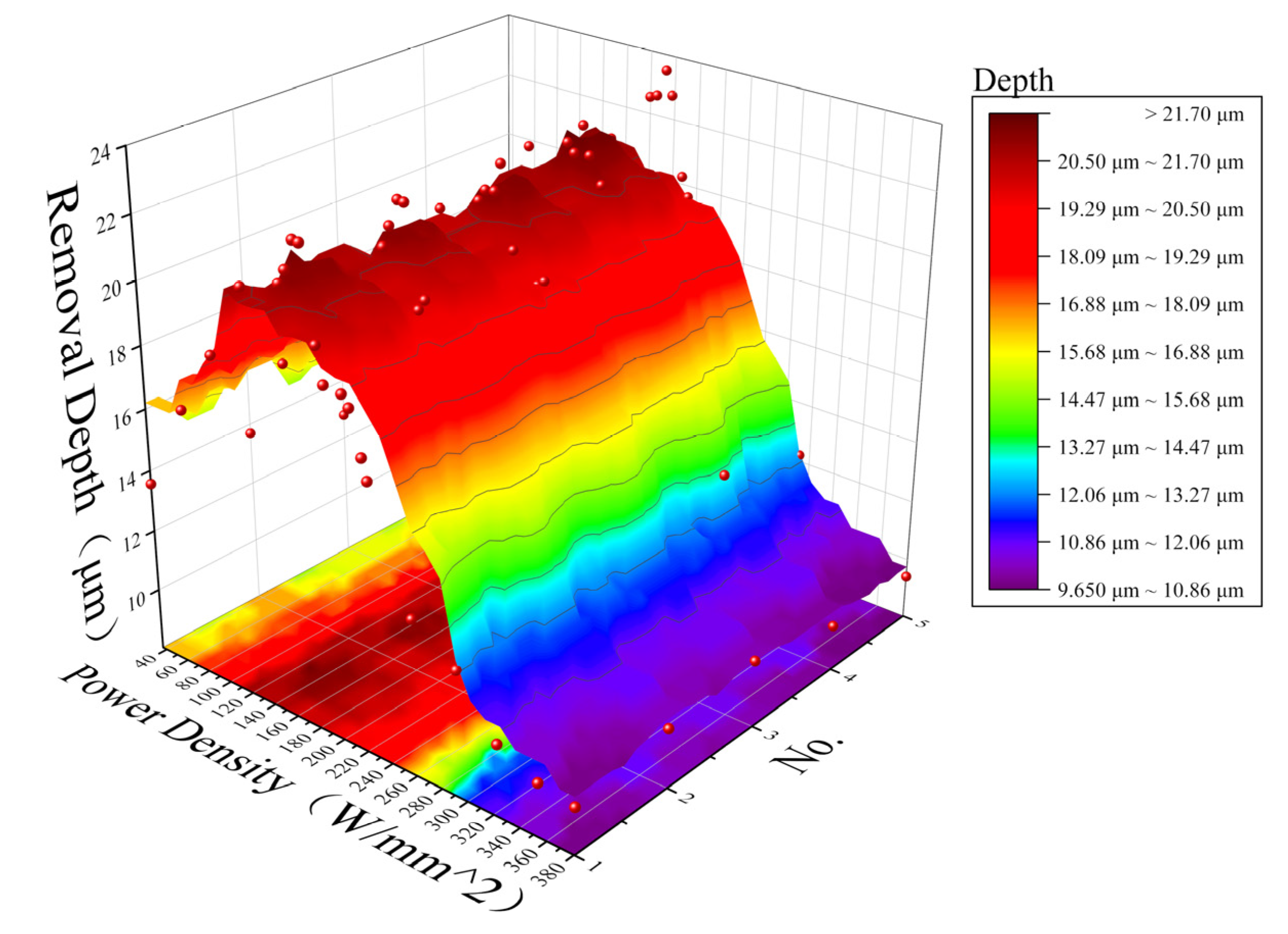
Figure 4 shows the relationship between the removal depth of the first target and the power density (the overall trend of five experiments).
3.2. The Temperature Evolution and Cleaning Threshold of Epoxy Primer and Epoxy Varnish
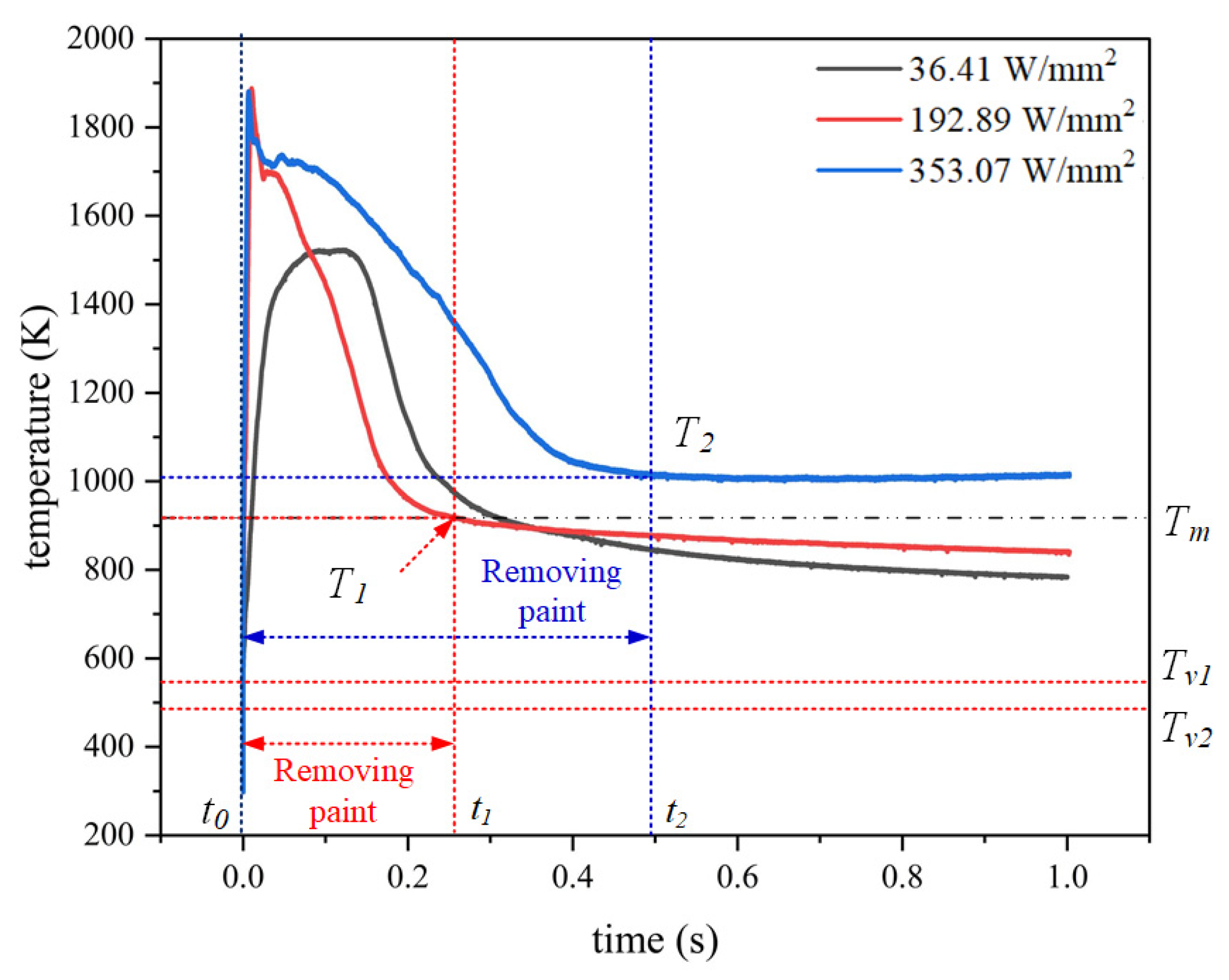
In
Figure 5, the vaporization point of the epoxy primer is
Tv1 = 548.15 K, the vaporization point of epoxy varnish is
Tv2 = 497.15 K, and the melting point of 7075 aluminum alloy is
Tm = 908.15 K. It is defined as
t0 when the temperature reaches the vaporization point of the paint layer. For the epoxy primer + epoxy varnish coating system, the same laser power density was selected to start the experiment due to the similar composition of epoxy varnish and epoxy primer.
As shown in
Figure 5, when the laser power density was 36.41 W/mm
2, the vaporization points
Tv2 and
Tv1 of epoxy varnish and epoxy primer were reached at
t0 = 0.6 × 10
−5 s, and then the coating began to be removed, and the temperature was 564.81 K. The temperature rise interval was 0–0.01 s. Due to the low laser power density, the temperature rise was relatively slow at this time and entered the temperature platform at 0.08 s, which was caused by the insufficient laser to continue to remove the paint layer. After 0.13 s, a too-low power density could not remove the remaining paint layer, and the aluminum alloy began to dissipate heat, resulting in a decrease in temperature.
When the power density was 192.89 W/mm2, the vaporization points Tv2 and Tv1 of epoxy varnish and epoxy primer were reached at t0 = 0.2 × 10⁻⁵ s. The paint removal started and the temperature was 566.84 K. The heating interval was 0–0.007 s. At this time, due to the heat conduction, the two coatings began to phase change. It entered the temperature platform at 0.02 s, and the temperature began to decrease slowly with the removal of paint. t0 to t1 is the paint removal interval.
With the paint removal completed, the laser directly acts on the aluminum alloy substrate, where T1 (0.27 s, 907.78 K) the temperature dropped to the melting point of the aluminum alloy. Since the paint layer was removed, the temperature changed from a downward trend to a flat one. In this time, the temperature curve is the temperature of laser irradiation of aluminum alloy. Since the temperature is lower than the melting point of aluminum alloy, there is no matrix damage.
When the power density was 353.07 W/mm2, the temperature rapidly increased to the vaporization point of the two coatings (t0 ≤ 0.1 × 10⁻⁵ s), and the heating interval was 0–0.006 s. At 0.09 s, the phase-change coatings were removed and entered the temperature platform. The slow temperature drop at 0.09–0.49 s is caused by the excessive laser power. The range of t0 to t2 is paint removal and the temperature decreases rapidly with the decrease of paint. When the temperature decreases to the lowest temperature T2 (0.49 s, 1009.06 K), the paint is completely removed and the laser directly acts on the aluminum alloy. Excessive laser power directly affects the aluminum alloy substrate, resulting in aluminum alloy melting and temperature rise.
For the two-layer coating system, when the laser power density was the same, the peak temperature of the No. 2 target was not as high as that of No. 1. This inconsistency may be due to the smooth and white surface of the epoxy varnish. The laser absorption capacity was worse than that of the No. 1 target, which will increase the optimal cleaning threshold. When the laser is applied, the upper paint film starts to be cleaned when the temperature reaches the vaporization point, while the lower paint absorbs heat, and the temperature also rises to the vaporization point. When the upper layer of paint is removed, the lower layer of paint will start to be removed immediately. Therefore, the paint removal process of No. 2 target material was faster than that of the No. 1 target material.
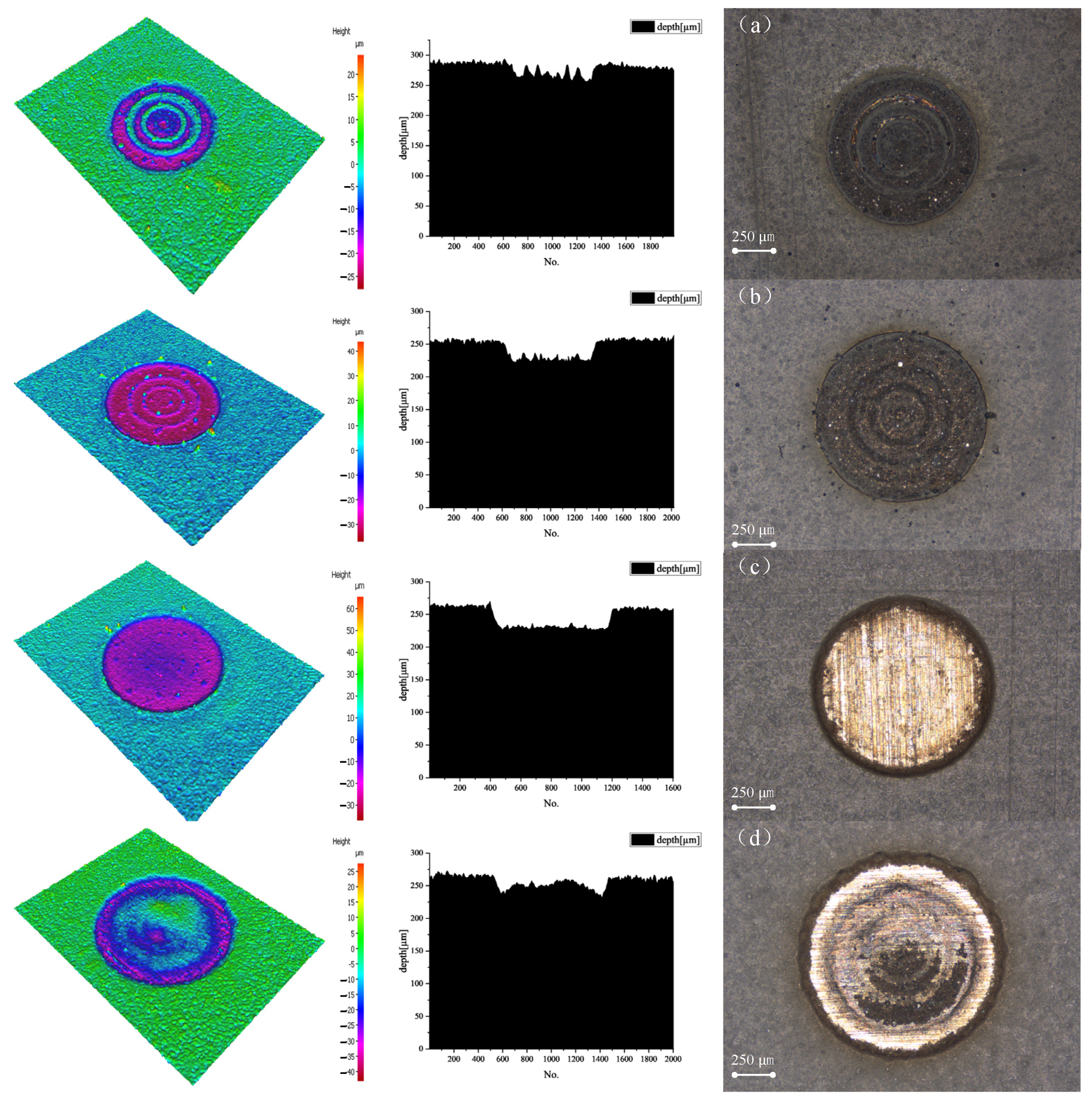
When the laser power density was 36.41 W/mm
2, the thermal effect produced gas on the surface of the target. The automatic three-dimensional surface measurement instrument showed that the upper layer of the paint was removed, and the cleaning depth was 15.9347 μm (
Figure 6a). The boundary between the epoxy primer and epoxy varnish layers can be observed clearly. When the power density was 187.54 W/mm
2, the paint layer melted, and black smoke was emitted. Moreover, the removal depth was 28.0275 μm (
Figure 6b).
When the laser power density was 192.90 W/mm
2, the surface of the target had a black substance formed via carbonization of the paint, and the removal depth detected by the automatic three-dimensional surface measuring instrument was 30.2406 μm (
Figure 6c). The cleaning effect was excellent, and no matrix damage was established. When the power density increased to 353.07 W/mm
2, the laser action point produced dazzling light, and the surface of the target produced black smoke. Using the automatic three-dimensional surface measuring instrument, matrix damage was established (
Figure 6d), and the removal depth was 10.4756 μm.
Thereafter, the surface of the cleaned sample was examined. The surface of the target after cleaning with a power density of 36.41 W/mm2 was rough, and the boundary between the paint layers was clearly visible. Nevertheless, the epoxy varnish residue was visible. The epoxy primer or surface of the aluminum alloy could not be exposed after blowing compressed air. The epoxy varnish layer was removed after cleaning with a power density of 187.54 W/mm2. After the compressed air was blown, part of the surface was exposed, but the surface was still rough. After cleaning with 192.90 W/mm2, the target material had a smaller residual paint layer, and the surface of the aluminum alloy that was exposed after blowing the compressed air was smooth and flat. When the power density was 353.07 W/mm2, the target material produced significant damage.
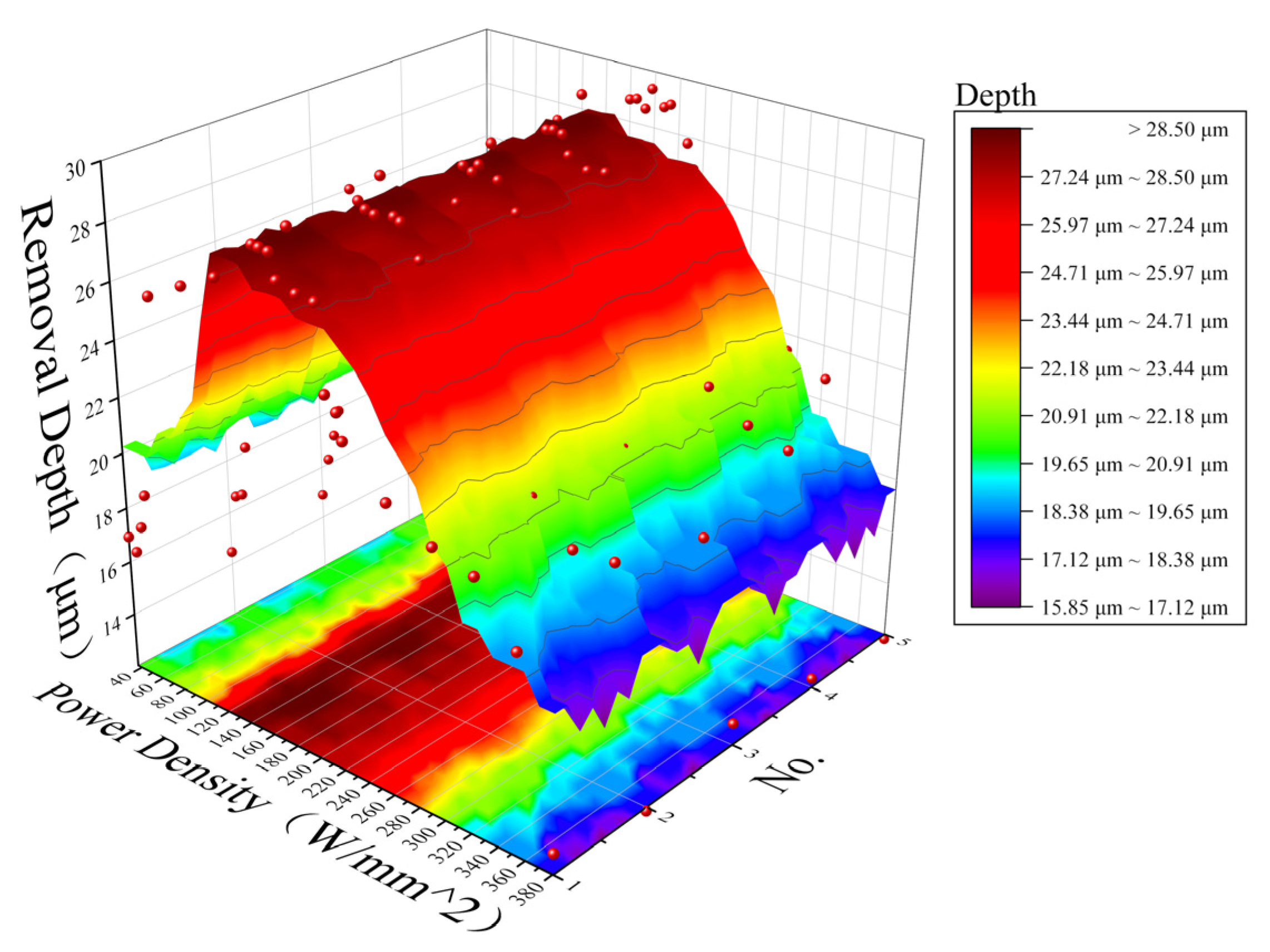
Figure 7 shows the relationship between the removal depth of the second target and the power density (the overall trend of five experiments).
3.3. The Temperature Evolution and Cleaning Threshold of Epoxy Primer, Epoxy Varnish, Alkyd Paint
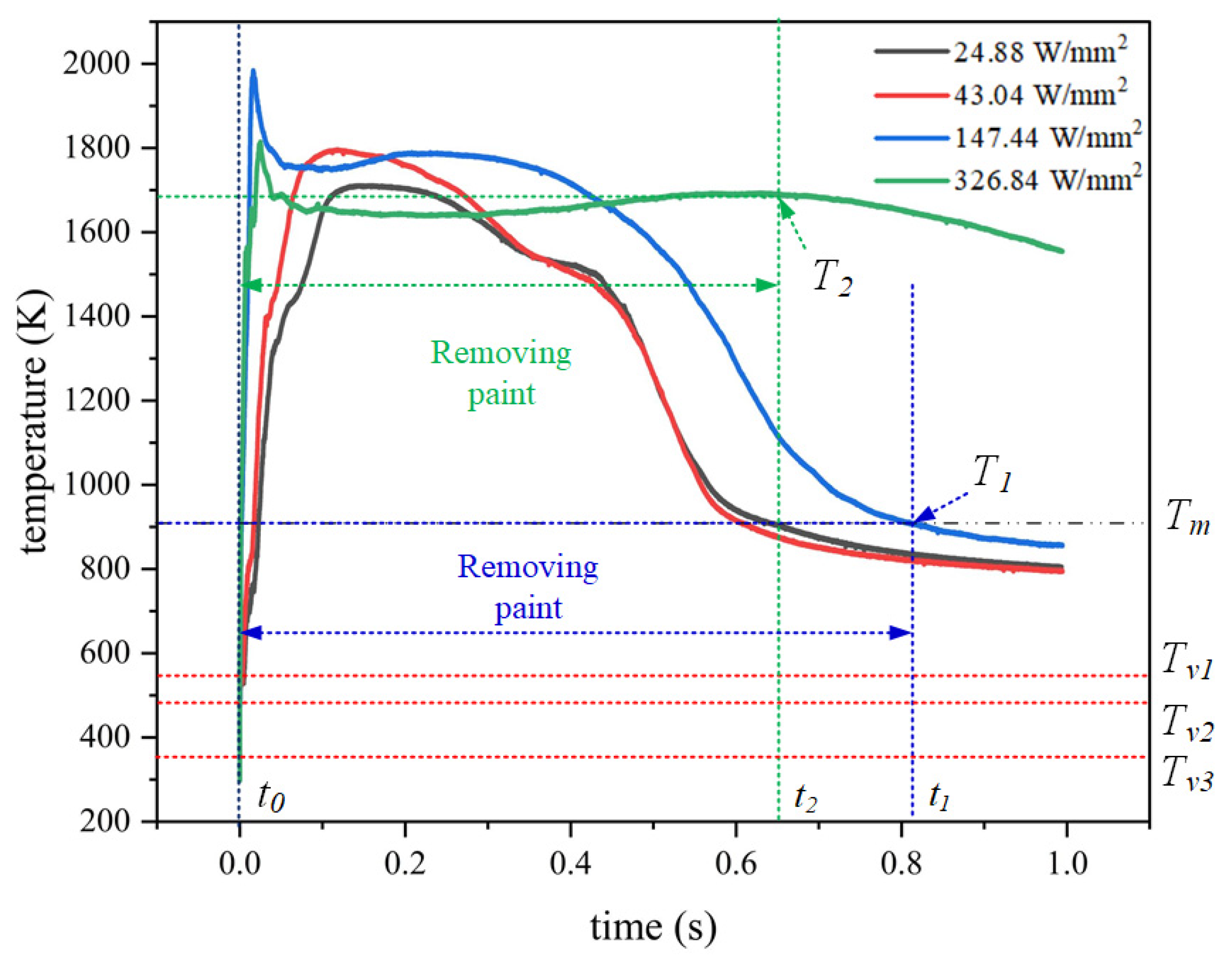
In
Figure 8, the vaporization point of epoxy primer is
Tv1 = 548.15 K, the vaporization point of epoxy varnish is
Tv2 = 497.15 K, the vaporization point of alkyd paint is
Tv3 = 350.15 K, and the melting point of 7075 aluminum alloy is
Tm = 908.15 K. It is defined as
t0 when the temperature reaches the vaporization point of the paint layer.
When the laser power density was 24.88 W/mm2, it reached the vaporization point Tv3 of the alkyd paint when t0 = 0.5 × 10⁻⁵ s, the paint began to be removed, and the temperature was 473.27 K. The temperature rose to the vaporization point of the epoxy varnish at 0.7 × 10⁻⁴ s, at which time the temperature was 497.72 K. At 0.002 s, the temperature rose to the vaporization point of the epoxy primer, at which time the temperature was 548.74 K. The heating interval was 0–0.12 s, and the slow heating at this time was due to the low laser power. It entered the temperature plateau at 0.13 s, and the slow drop in temperature after 0.24 s was caused by the removal of paint. As the paint layer cannot be completely removed, the later temperature is relatively gentle. At 0.35 s, due to the heat dissipation of the substrate, the temperature began to drop.
When the laser power density is increased to 43.04 W/mm2, it reaches the vaporization point Tv3 of the alkyd paint when t0 = 0.5 × 10⁻⁵ s, and the paint starts to be removed, the temperature is 476.07 K. The temperature rises to the vaporization point of the epoxy varnish at 0.6 × 10⁻⁴ s, and the temperature is 497.81 K at this time. The temperature rises to the vaporization point of the epoxy primer at 0.0013 s, at which time the temperature is 549.03 K. The heating interval is 0–0.1 s, after which the temperature shows a slow downward trend, which is caused by the low paint removal rate. The temperature dropped rapidly after 0.45 s, which proved that the aluminum alloy began to dissipate heat.
When the laser power density was 147.44 W/mm2, it reached the vaporization point Tv3 of the alkyd paint when t0 = 0.3 × 10⁻⁶ s, the paint began to be removed, and the temperature was 488.44 K. The temperature rose to the vaporization point of the epoxy varnish at 0.8 × 10⁻⁶ s, at which time the temperature was 501.58 K. The temperature rose to the vaporization point of the epoxy primer at 0.8 × 10⁻⁵ s, at which time the temperature was 549.03 K. The overall heating interval was 0–0.01 s, and the temperature began to drop due to the removal of the alkyd paint on the surface.
After the 0.06 s alkyd paint was removed, the cleaning of epoxy varnish and epoxy primer began, and the temperature rose slowly and decreased as the paint decreased. t0 to t1 is the paint removal interval. After the paint is removed, the laser will directly act on the aluminum alloy substrate, where the temperature drops to the melting point of the aluminum alloy at T1 (0.81 s, 908.33 K), and the overall paint removal process is longer. Since the paint layer has been removed, the temperature curve at this time is relatively gentle, which is the temperature change of the laser irradiated aluminum alloy. At this time, the temperature is lower and no damage to the substrate will occur.
When the power density acts at 326.84 W/mm2, it reaches the vaporization point Tv3 of the alkyd paint when t0 = 0.2 × 10⁻⁶ s, the temperature is 479.93 K, and the paint begins to be removed. The temperature rises to the vaporization point of the epoxy varnish at 0.6 × 10⁻⁶ s, at which time the temperature is 509.31 K. The temperature rises to the vaporization point of the epoxy primer at 0.1 × 10⁻⁵ s, at which time the temperature is 559.56 K. The temperature rise interval is 0–0.03 s.
A too-high power density accelerates the removal of alkyd paint, causing the alkyd paint to be removed before it reaches the peak temperature, and thus the peak temperature is reduced, and then the epoxy varnish and epoxy primer are removed. The epoxy varnish and epoxy primer are removed at 0.07 s. From t0 to t2 is the paint removal interval. Due to the high laser power, the temperature starts to rise in this time.
When the temperature rises to T2 (0.49 s, 1692.93 K), the complete disappearance of the paint causes the temperature to start to drop, and the laser directly acts on the aluminum alloy. Excessive laser power directly acts on the aluminum alloy substrate and enters the molten phase transition state of the aluminum alloy, and the substrate is damaged at this time.
The removal mechanism of the three-layer coating system is similar to the removal mechanism of the double-layer coating, but the optimal cleaning threshold of the No. 3 target is significantly lower than the other two targets. This difference can be attributed to the fact that when the alkyd paint layer is cleaned by laser, because the alkyd paint has better absorption of the laser, the heat transferred by the alkyd paint at this time is greater than the heat when the laser is directly applied to the epoxy varnish, and the vaporization point of alkyd paint is low, resulting in a lower optimal cleaning threshold when the paint is completely removed.
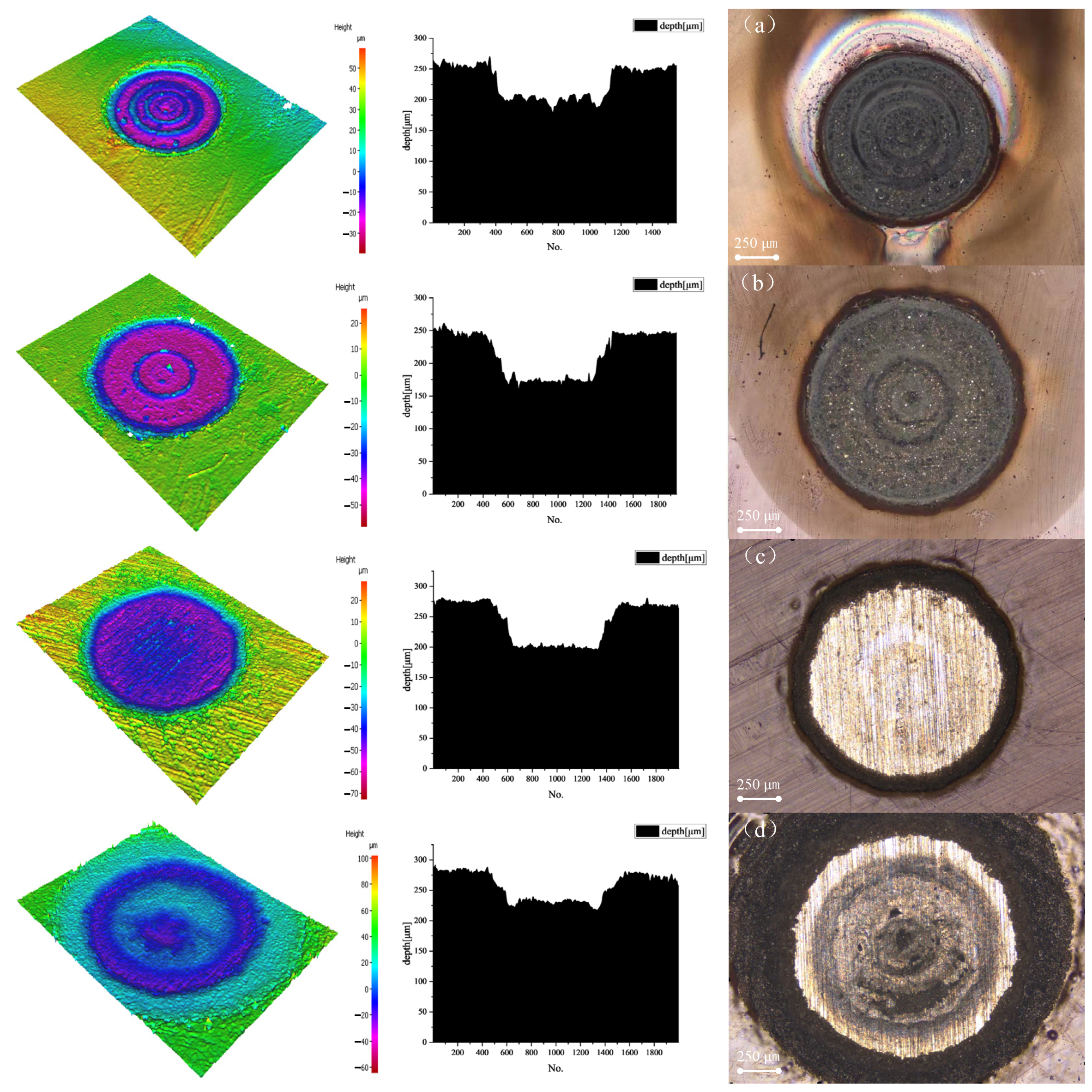
When the laser power density was 24.88 W/mm
2 for 1 s, the cleaning was completed immediately because the alkyd paint vaporization and ablation temperature were low. The ablation depth confirmed using the automatic three-dimensional meter second measuring instrument was 43.7498 μm (
Figure 9a). The dividing line between the epoxy varnish and epoxy primer was observed clearly. When the laser power density was 43.04 W/mm
2, the epoxy varnish layer was cleaned, and the epoxy primer layer entered the final stage with a removal depth of 69.0322 μm (
Figure 9b).
The removal depth was 73.5031 μm (
Figure 9c) when the laser power density was 147.44 W/mm
2. The surface of the substrate was intact, and the removal depth reached the standard, which was the suitable cleaning threshold. The substrate was damaged (
Figure 9d) when the power density increased to 326.84 W/mm
2, and the removal depth was 47.4668 μm.
The surfaces of the cleaned samples were then inspected. The surface of the cleaned target with a power density of 24.88 W/mm2 was rough, and the paint layer was tightly combined with the paint layer. There was no change in the surface of the specimen after blowing compressed air. After cleaning with a power density of 43.04 W/mm2, the alkyd paint and epoxy varnish layers were removed, and the surface after blowing compressed air was still rough. Most of the aluminum alloy is exposed on the surface of the target after cleaning with 147.44 W/mm2. After the compressed air was blown, the surface of the substrate was smooth and flat. When the power density was 326.84 W/mm2, the target had a molten pit, and the matrix was damaged.
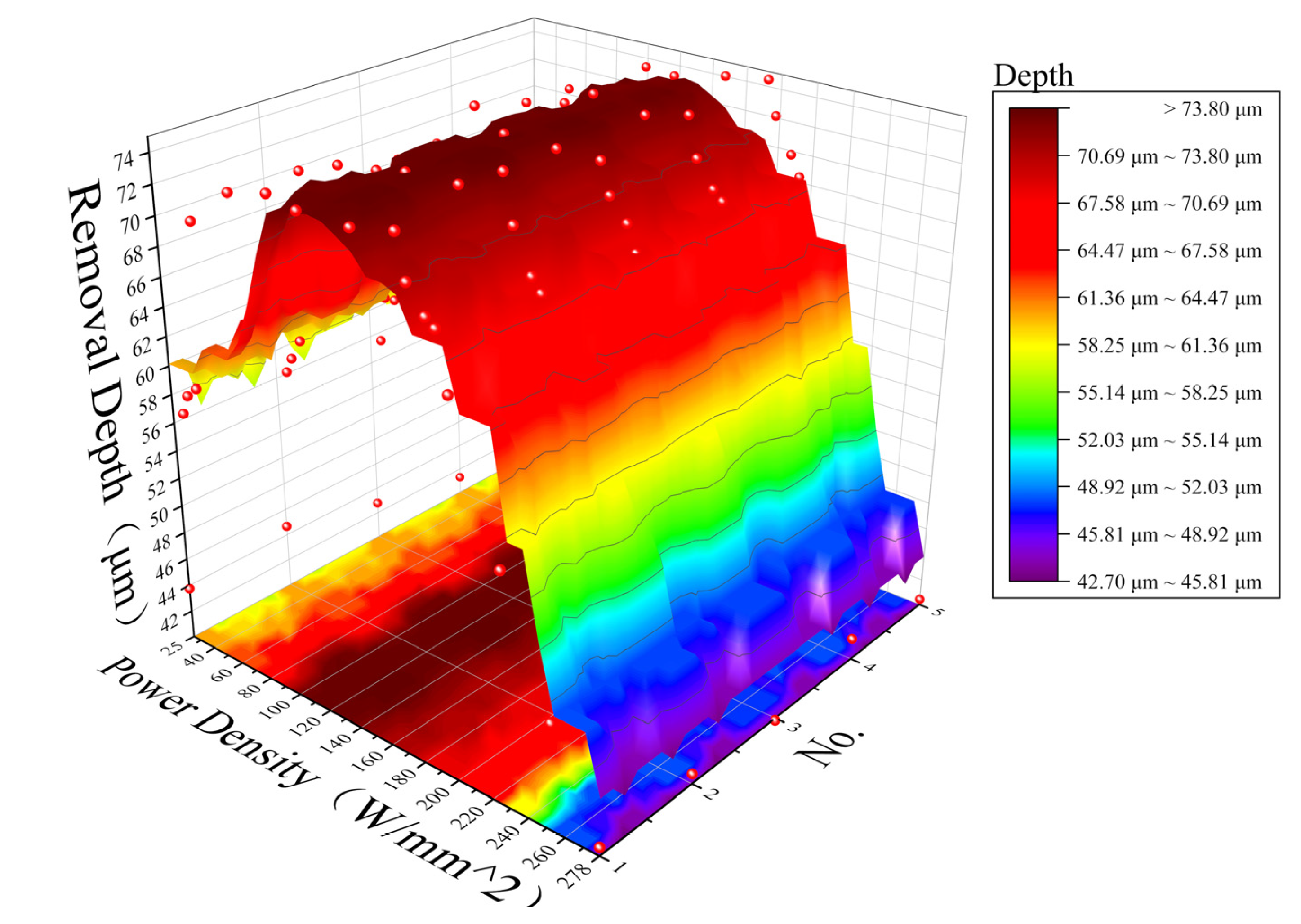
Figure 10 shows the relationship between the removal depth of the third target and the power density (The overall trend of five experiments).
3.4. Influence of Thermal Effect on Cleaning Threshold in the Process of Paint Removal and Mechanism Analysis
It can be seen from the experimental results that the optimal cleaning threshold 147.44 W/mm2 for the three-layer structure target was significantly lower than the cleaning threshold 192.89 W/mm2 for the two-layer structure target. The composition of the epoxy primer and epoxy varnish was similar, and the two-layer structure target can be regarded as a unified structure for analysis (collectively referred to as epoxy paint).
The heat conduction equation can be expressed as follows:
Among these, and represent the density, heat capacity and thermal conductivity of each layer. represents the temperature distribution in time.
For the No. 3 target, the surface boundary conditions of epoxy paint are:
Among them,
is the thermal conductivity of the material,
is the absorption rate of the material,
is the thickness of the epoxy paint, and
is the strength of the alkyd paint after the incident laser transmission
The boundary conditions of the substrate surface are:
For the No. 2 target, the surface boundary conditions of epoxy paint are:
The boundary conditions of the substrate surface are:
It can be seen from Equations (1) and (2) that the absorbed heat of epoxy coating for target 3 mainly comes from the laser power transmitted through alkyd coating and the heat conduction of alkyd coating, and its heat is affected by the inherent material properties of the two coatings. Since the laser absorption coefficient of alkyd paint is greater than that of epoxy paint, the inner temperature of the spot is higher when the laser acts on alkyd paint, and the heat conduction by alkyd paint is higher. At the same time, due to the laser transmission effect, the temperature of the epoxy paint is higher.
It can be seen from Equation (4) that the power required for the complete removal of the coating by the No. 3 target is small. It can be seen from Equation (2) that the absorbed heat of epoxy coating for target 3 mainly comes from the laser transmitted through alkyd coating and the heat conduction of alkyd coating, and its heat is affected by the inherent material properties of the two coatings. Since the laser absorption coefficient of alkyd paint is greater than that of epoxy paint, the inner temperature of the spot is higher when the laser acts on alkyd paint, and the heat conduction by alkyd paint is higher. It can be seen from Equation (3) that the power required for the complete removal of the coating by the No. 3 target is small.
Similarly, it can be observed in Equation (5) that white epoxy paint has weak light absorption, and the transmitted laser power is small. It can be seen from Equation (6) that greater laser power is needed to achieve the melting gasification point of epoxy paint. Therefore, the best cleaning threshold of the No. 3 target is lower than that of the No. 2 target.
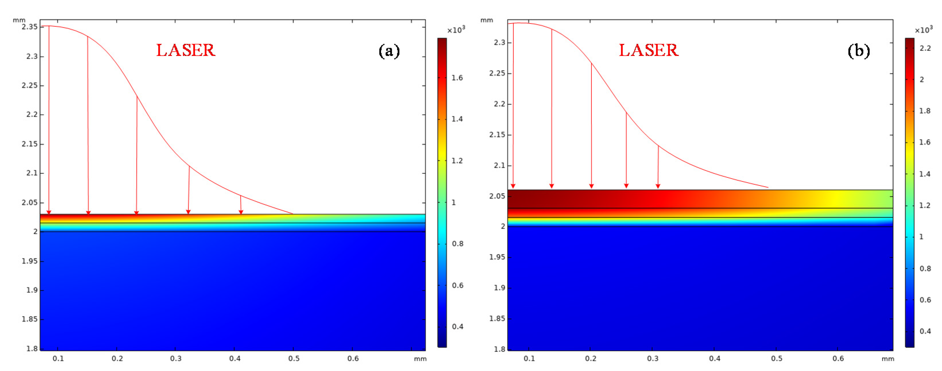
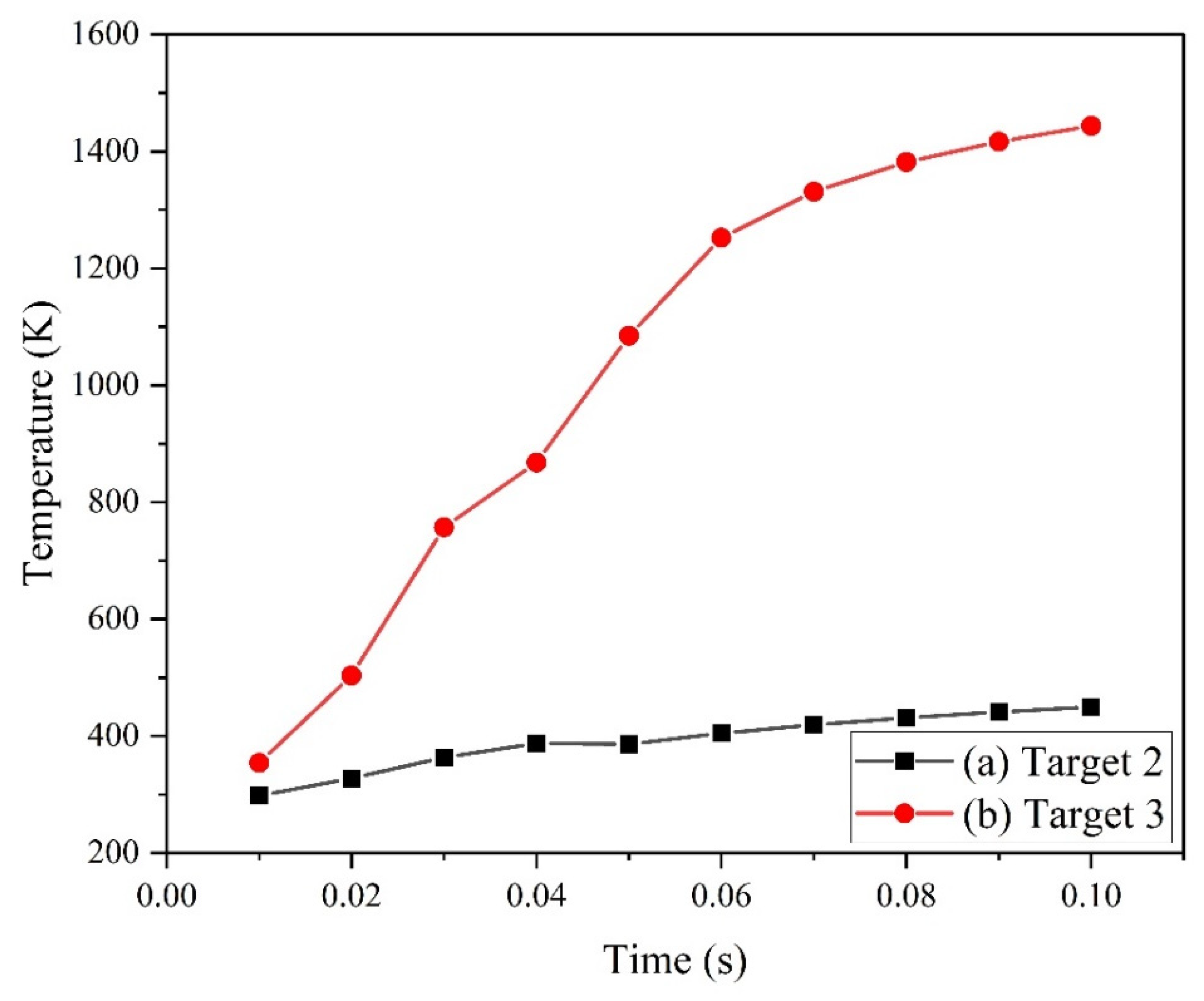
Figure 11 shows the calculation results of the finite element analysis software. The results show that, under the same laser conditions, the heat affected area and temperature of the third target were greater than those of the second target. At the same time, due to the large heat affected area of alkyd paint, the temperature rise of epoxy paint was higher, and it was easier to achieve the melting vaporization state. In
Figure 12, (a) is the temperature rise curve of the upper surface of target 2, and (b) is the surface temperature rise curve of the substrate of target 3. It can be seen that, under the same power density, the temperature rise of the substrate of target 3 is higher, which is sufficient to remove the paint layer on the substrate.
During the cleaning process, due to the temperature gradient between the lacquer layer and the substrate, thermal stress is generated, of which radial stress and circumferential stress play the main role. When the generated thermal stress is greater than 148 MPa of the adhesion force between epoxy primer and aluminum alloy, the removal of metal surface paint can be achieved [
24].
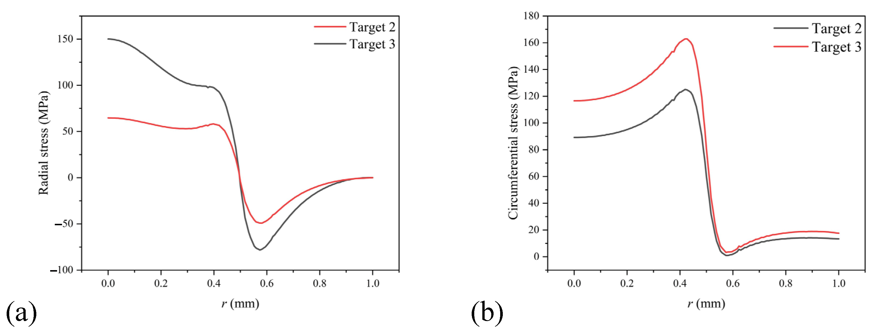
Figure 13a shows the radial stress distribution at the interface between the aluminum alloy and the epoxy primer layer when the laser power density is 147.47 W/mm
2. As shown in the figure, when the laser is applied to the No. 3 target, the radial stress curve at the center of the material appears as tensile stress with a value of 150.13 MPa. As the radial distance increases, tensile stress quickly converts to compressive stress near the edge of the spot and its highest value is 76.09 MPa. When the laser acts on the No. 2 target, the center of the light spot also shows a tensile stress with a value of 64.76 MPa. As the radial distance increases, the stress change trend of No. 2 target material is similar to that of No. 3 target material, which turns into a compressive stress at the spot boundary with a maximum value of 49.16 MPa. The maximum value of tensile stress and compressive stress are both less than 148 MPa.
Figure 13b shows the circumferential stress distribution at the interface between the aluminum alloy and the epoxy primer layer when the laser power density is 147.47 W/mm
2. As shown in the figure, when the laser acts on the No. 3 target, the circumferential stress is mainly tensile stress, which rises slowly to the edge of the spot and rises to the highest value of 162.97 MPa at the edge of the action area. The laser also caused the No. 2 target to produce tensile stress, and the stress change trend is similar to that of the No. 3 target. The highest value was 125.08 MPa at the edge of the spot.
From the distribution of radial stress and circumferential stress, we can see that, when laser cleaning paint, the radial stress at the center of the spot is larger, and the circumferential stress at the edge of the spot is larger. The two stresses of the No. 2 target were smaller than the adhesion between the paint and aluminum alloy, which is less helpful for paint removal. Both stresses of the No. 3 target material were greater than the adhesion between paint and aluminum alloy. At the same time, there as a large stress difference at the edge of the light spot, which will help with the cleaning of the paint layer. This also resulted in the optimal cleaning threshold of the No. 3 target being smaller than that of the No. 2 target.
4. Discussion
We measured the temperature change curve of each experiment (
Figure 2,
Figure 5 and
Figure 8). From the figure, we can find that the temperature change trend of each experiment first increased and then decreased, and the trend was approximately stable in the later period. After the laser acts on the target, the paint layer paint absorbs the laser, and the temperature rises to the vaporization point of the paint layer, at which time the temperature is higher. According to the temperature at the optimal cleaning threshold of the double-layer target material (
Figure 5, 192.89 W) and the three-layer structure target material (
Figure 8, 147.44 W), it can be seen that, for the multilayer paint layer structure, when the laser is applied to different paint layers, the temperature trend will change obviously, such as a slope, drop, etc.
It can be observed in the removal depth trend (
Figure 4,
Figure 7 and
Figure 10) that, as the power density increases, the removal depth increases linearly and reaches the maximum removal depth near the optimal cleaning threshold. At this time, continuing to increase the power density cannot continue to increase the removal depth. On the contrary, the aluminum alloy matrix will be deformed after being heated and melted due to the higher power density, resulting in a decrease in the average removal depth.
The analysis found that the temperature and stress changes of the material were mainly concentrated near the irradiated part of the light spot and decrease toward the edge of the laser working area. The stress value appears as an abnormal stress peak at the edge of the light spot, which is conducive to the removal of the paint layer, but the stress value shown in the data is always low, which is near the adhesion between the paint and the substrate (148 MPa).
The value of the temperature field was much larger than the vaporization points of the paint layer. The temperature field value of the model was much larger than the vaporization points of the paint layer. Bright flames and smoke appeared during the experiment, and, after laser irradiation, the surface of the substrate showed a relatively obvious temperature rise, and a slight paint melting phenomenon appeared at the edge of the action area. According to the data of temperature and stress distribution, for the continuous laser removal of aluminum alloy surface paint, the main action mechanism of laser paint removal is the ablation mechanism, and there is a thermomechanical effect to assist in cleaning.

 ,
, 


