Article

Aerial Projection 3D Display Based on Integral Imaging

1
College of Electronics and Information Engineering, Sichuan University, Chengdu 610065, China
2
School of Instrumentation Science and Optoelectronics Engineering, Beihang University, Beijing 100191, China
*
Author to whom correspondence should be addressed.
Photonics 2021, 8(9), 381; https://doi.org/10.3390/photonics8090381
Submission received: 3 August 2021 / Revised: 1 September 2021 / Accepted: 3 September 2021 / Published: 9 September 2021
(This article belongs to the Special Issue Smart Pixels and Imaging)

Abstract

:
We proposed an aerial projection 3D display based on integral imaging. It is composed of a projector, a lens-array holographic optical element (HOE), and two parabolic mirrors. The lens-array HOE is a diffraction grating and is made by the volume holography technique. The lens-array HOE can be produced on a thin glass plate, and it has the optical properties of a lens array when the Bragg condition is satisfied. When the display beams of the element image array (EIA) are projected on the lens-array HOE, 3D images can be reconstructed. The two parabolic mirrors can project 3D images into the air. The Bragg-unmatched light simply passes through the lens-array HOE. Therefore, the aerial projection 3D images appear to be imaged in the air without any medium. In the experiment, a BenQ projector was used for the projection of 3D images, with a resolution of 1600 × 1200. The diameter and the height of each parabolic mirror are 150 mm and 25 mm, respectively. The inner diameter of the parabolic mirror is 40 mm. The 3D images were projected in the air, and the experimental results prove the correctness of our display system.

1. Introduction

Aerial projection or floating 3D display has been widely investigated. There are many types of floating 3D displays. For example, the light-field display can present floating glass-free 3D images in the air, but more projectors are needed [1,2,3], or scanning [4,5,6], rotating [7,8,9,10,11], and processing are required. Therefore, the system of the light-field display is quite complex and expensive. Volumetric displays can also float 3D images in the air, and they consist of bubbles [12,13], photoactivatable dye [14], nonlinear optical crystals [15], quantum dots [16], fog [17,18], and water drops [19]. However, a special medium or multi-beam laser simultaneous projection is needed, so the volumetric display is impractical because of the difficulty of fabrication and construction. The holographic display can also project 3D images in the air [20,21,22,23,24,25,26], but there are still some bottleneck problems, especially the large computational amount and quantity of data.
Integral imaging can also project 3D images floating in the air [27,28,29,30], which is an ideal way to display 3D images. It can be formed via arbitrary viewpoint without supplementary glasses or tracking devices [31,32]. In addition, it can provide observer accommodation cues and smooth motion parallax [33,34,35,36]. The floating 3D display system-based integral imaging can be divided into two categories: one is swept type, and the other is static type. The swept-type floating 3D display system-based integral imaging generally consists of a high-speed rotating motor [10,29,30]. The system is bulky and noninteractive. To solve these issues, there are many studies on the static-type floating 3D display system-based integral imaging, because the system is free of spinning devices [27,28,32,33,34,35]. Therefore, the static-type floating 3D display-based integral imaging has the advantages of simple structure and easy implementation.
In this paper, we propose a simple-structured aerial projection 3D display based on integral imaging, which is composed of a projector, a lens-array HOE, and two parabolic mirrors. It can present a floating 3D display with only one projector and no spinning devices. The observers can touch the 3D images directly; the principles and the characteristics of the proposed aerial projection 3D display were analyzed through display experiments.

2. Principle of the Aerial Projection 3D Display

The principle diagram of the aerial projection 3D display based on lens-array HOE and parabolic mirrors is shown in Figure 1. The aerial projection 3D display is composed of a projector, a lens-array HOE, and a pair of parabolic mirrors. The lens-array HOE is made of volume holographic elements, which can be produced on a thin glass plate, and it has the optical properties of a micro-lens array when the Bragg condition is satisfied. The projection beam from a projector is called a display beam, and it is collimated through relay optics and a telecentric lens. The display beams with element image array (EIA) information are reflected by a mirror and projected onto the lens-array HOE, which satisfies the Bragg condition. Then, the 3D images can be reconstructed. The light rays of the reconstructed 3D images are reflected three times through the parabolic mirrors, and the 3D images are floating in the air. The Bragg-unmatched light rays simply pass through the lens-array HOE, and hence, the lens-array HOE has the advantage of a see-through display. Therefore, the 3D images are projected in the air by the parabolic mirrors, and the floating 3D images appear to be without any medium.

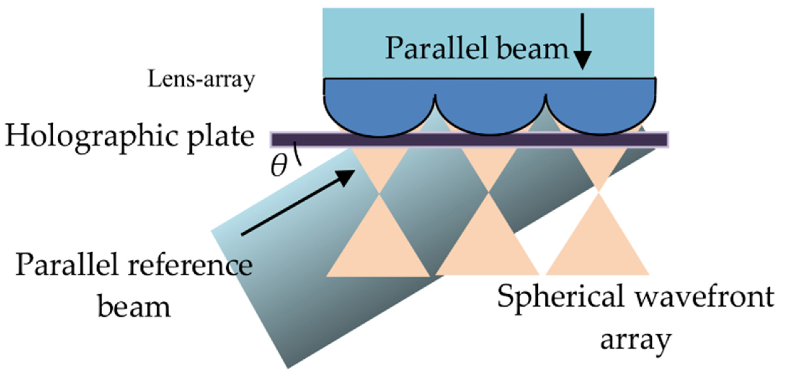
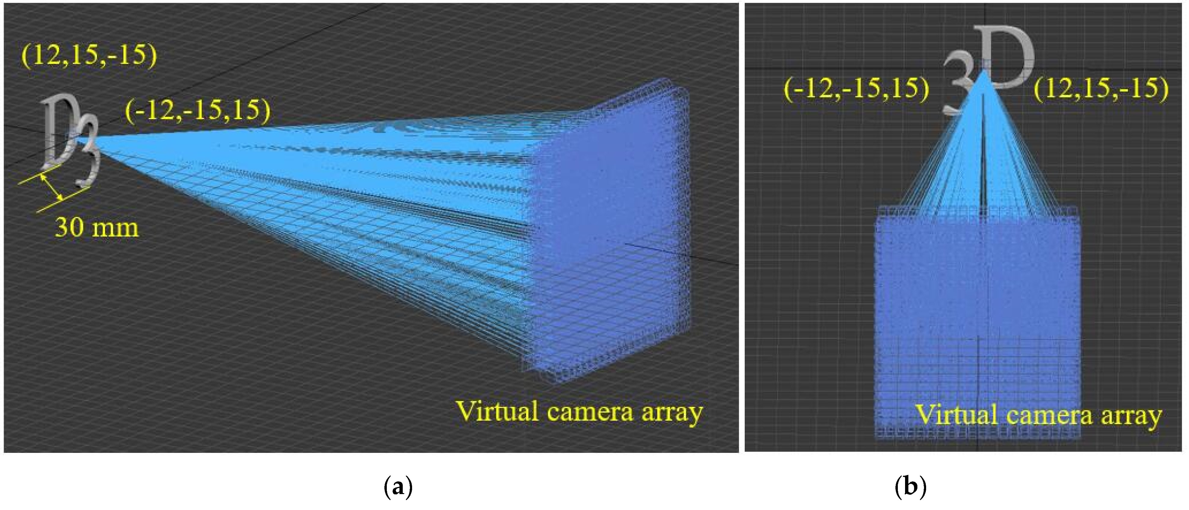
2.1. Fabrication Principle of the Lens-Array HOE

The fabrication principle of the lens-array HOE is shown in Figure 2. The green parallel beams are vertical incidents into the micro-lens array to form a spherical wavefront array, and the green parallel reference beams are incident into the holographic plate (green-sensitive photopolymer material) with the angle θ. The green parallel reference beams and spherical wavefront array are incidents into the holographic plate in the opposite directions. The spherical wavefront array interferes with the parallel reference beams, and the interference fringes are recorded on the holographic plate. Then, the lens-array HOE is fabricated. The thickness of the green-sensitive photopolymer material is 15 μm, the resolution is line/mm, the sensitive wavelength is 532 nm, the photosensitivity of photopolymers is 10 mJ/cm2, and the averaged refractive index is 1.47. The micro-lens array is used in this paper, which consists of a 150 × 150 micro-lens. The pitch of the micro-lens is 1 mm, and the focal length is 3.3 mm. Finally, a monochrome lens-array HOE with a size of 50 mm × 50 mm is fabricated.

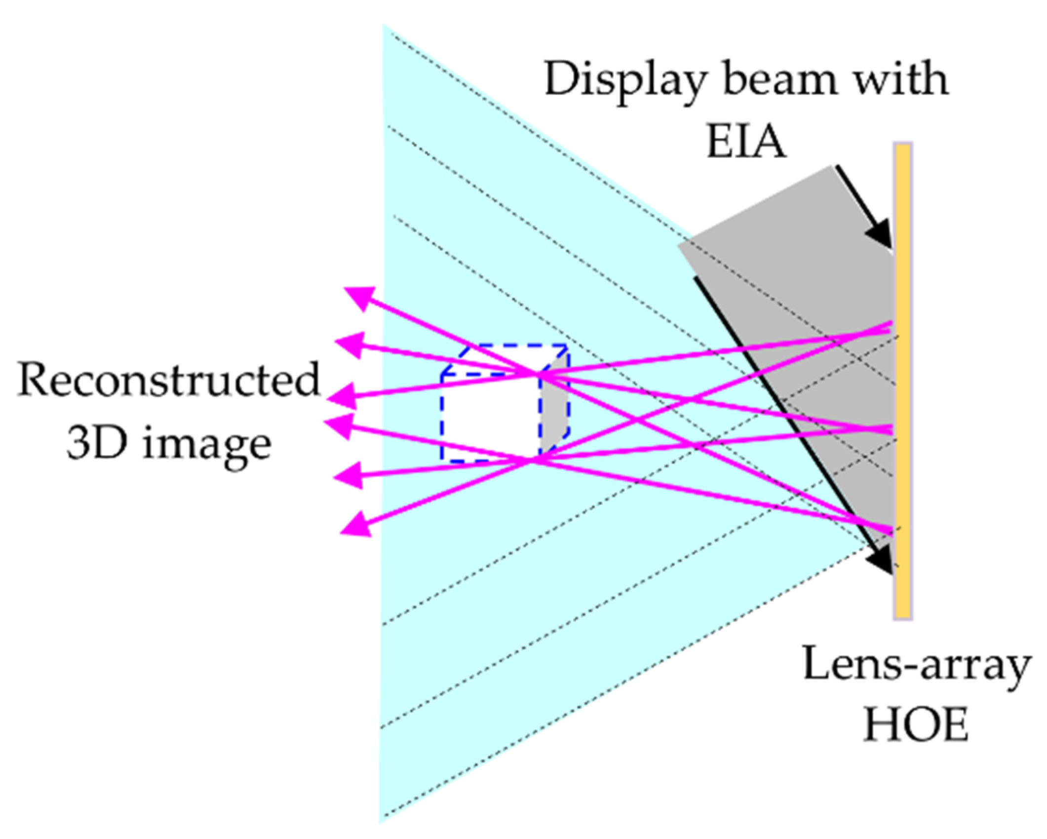
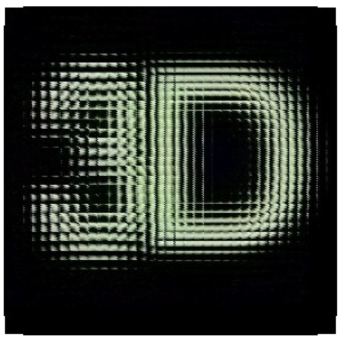
2.2. Reconstruction Principle of 3D Images

The reconstruction principle of 3D images using the lens-array HOE is shown in Figure 3. The lens-array is used as an image combiner in the proposed aerial projection 3D display. The lens-array HOE has the optical properties of a micro-lens array when the Bragg condition is satisfied. The projection beams from the projector are collimated by the relay optics and the telecentric lens. The projection beam is called a display beam when the display beams are projected onto the lens-array HOE with the angle θ, and then the Bragg condition is satisfied. The spherical wavefront array is reconstructed, so the lens-array HOE has the optical properties of a micro-lens array, which is generally used in the integral imaging 3D display [27,37]. When the display beams of EIA are projected onto the lens-array HOE with the angle θ, the 3D images are reconstructed in front of the lens-array HOE. The lens-array HOE also has the advantage of a see-through display.
The viewing angle of the reconstructed 3D images in Figure 3 can be expressed as
α = 2 arctan ( d 2 f )
where d is the diameter of the elemental holographic lens recorded on the holographic plate, and f is the focal length of the elemental holographic lens. The resolution of the 3D image is equal to the number of the elemental holographic lenses recorded on the holographic plate.

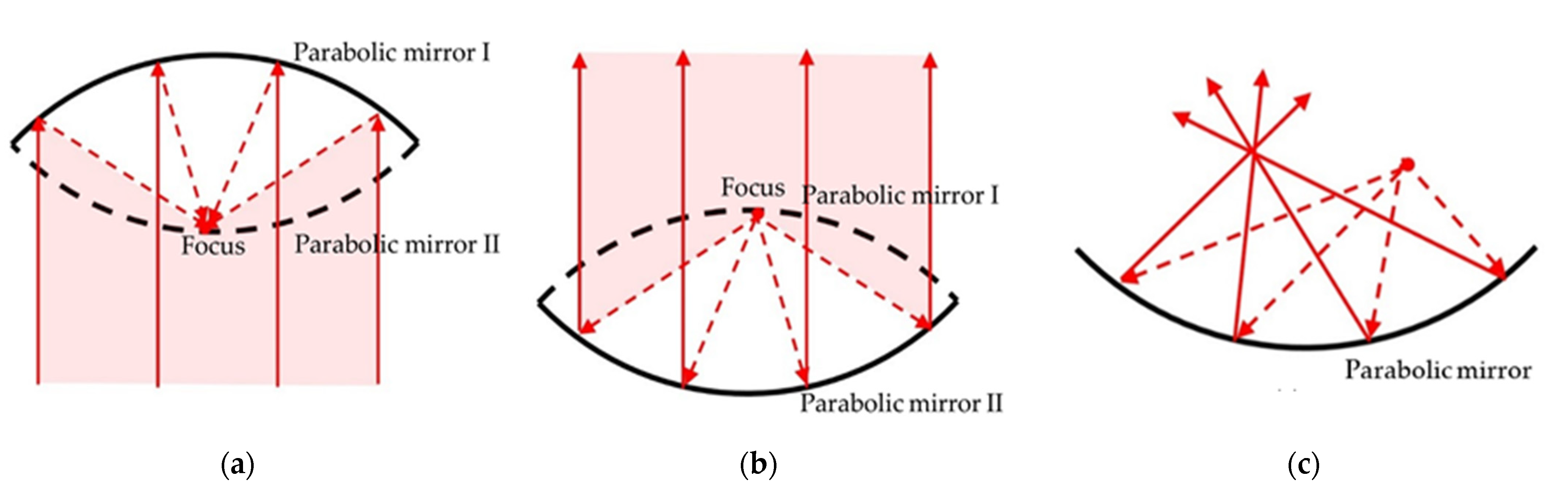
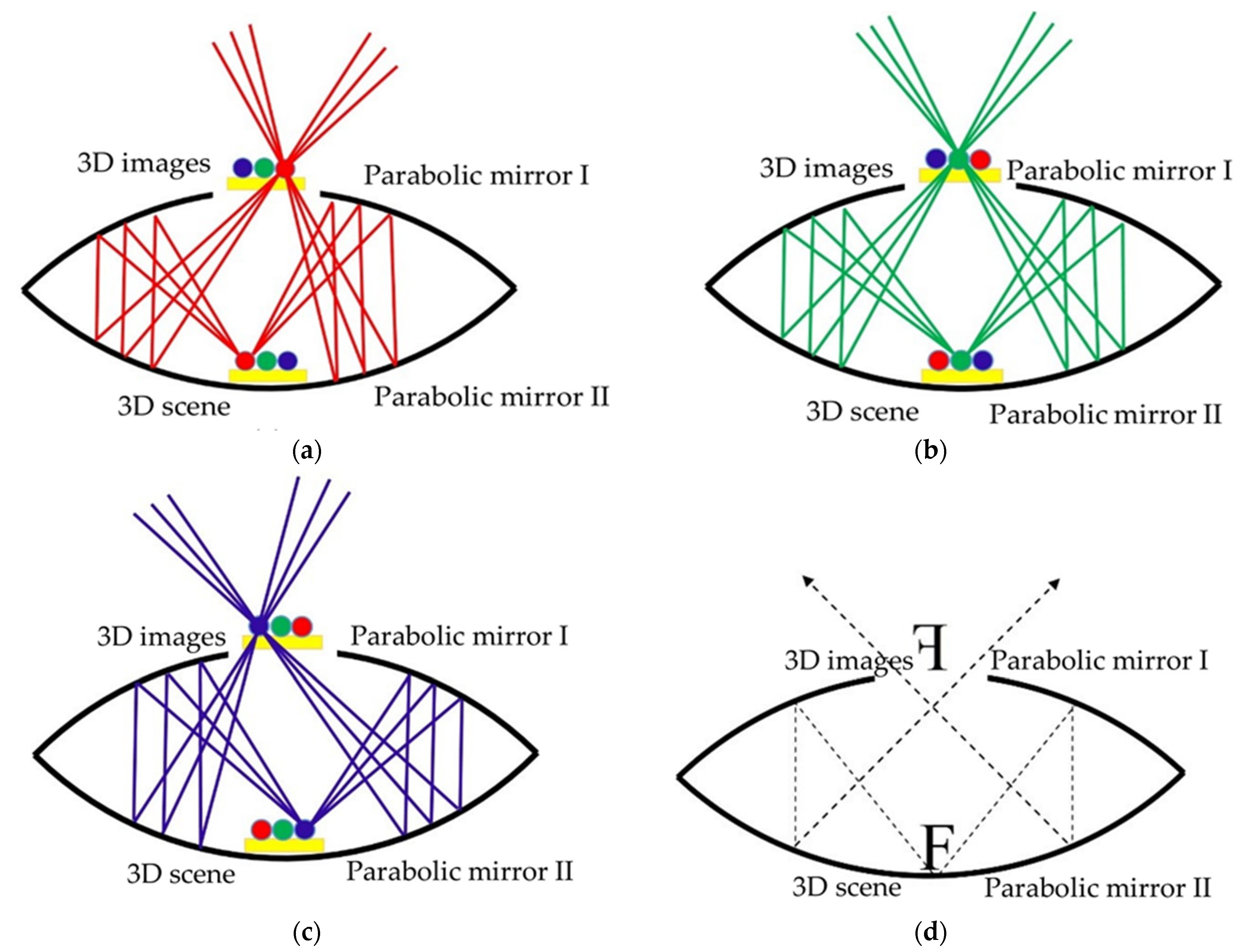
2.3. Imaging Principle of the Parabolic Mirrors

Parabolic mirrors are used for the aerial projection holographic 3D display many times. The parabolic mirrors imaging system is composed of two identical parabolic mirrors, and the reflective surfaces of these mirrors are on the concave side of the parabolic, as shown in Figure 4. The parabolic mirrors must satisfy the following two conditions: when a parallel beam is incident perpendicular to parabolic mirror I, the focus point is at the apex of parabolic mirror II, as shown in Figure 4a, and when the light source at the apex of parabolic mirror I passes to parabolic mirror II, the light rays become parallel beams, as shown in Figure 4b.
To meet the above conditions, parabolic mirror I has to meet the condition of the focal point at the vertex of parabolic mirror II, and parabolic mirror II also needs to satisfy the same conditions. To meet this condition, the focal point “f” is two times the “y” value at the extreme right (or extreme left) side of the parabola, because the double parabolic mirrors will be the same. The parabola profile of parallel mirrors I and II can be expressed as
y = x2/4f
f = 2y
where “f” is the characteristic value of the parabola, and “x” is the value at the extreme right of the parabola. The other parabolic mirror has the same characteristics, the light rays emitted by the point source on the right side are reflected by the parabolic mirror, and the light rays are focused on the left side of the parabolic mirror, as shown in Figure 4c.
The imaging principle of the parabolic mirrors is shown in Figure 5. One of the parabolic mirrors has an opening at the vertex of the parabola; when setting one parabolic mirror in front of the other, the focal point of one parabolic mirror is located at the vertex of the other parabolic mirror and vice versa. The 3D scene contains three balls: red, green, and blue, as shown in Figure 5a–c. The 3D scene is located at the vertex of parabolic mirror I, the light rays are emitted by the red ball by parabolic mirrors I and II, and finally, the light rays are reconstructed in the upper right side of parabolic mirror II, as shown in Figure 5a. The light rays are emitted by the red ball at the left side of the 3D scene and are equivalent to that emitted by a virtual red ball at the upper left side of parabolic mirror II. Therefore, through the reflection of parabolic mirrors I and II, the light rays are reconstructed in the upper right side of parabolic mirror II. The light rays emitted by the green ball at the center of the 3D scene are reflected by parabolic mirrors I and II, and a green ball is reconstructed at the vertex of parabolic mirror II, as shown in Figure 5b. The light rays emitted by the green ball in the 3D scene are reflected by parabolic mirror II into a parallel beam, and the parallel beam is concentrated at the apex of parabolic mirror II, which is reflected by parabolic mirror I. The light rays emitted by the blue ball in the 3D scene are reflected by parabolic mirrors I and II, which are reconstructed in the upper left side of parabolic mirror II, as shown in Figure 5c. The light rays emitted by the green ball at the right side of the 3D scene are equivalent to that emitted by a virtual green ball at the upper right side of parabolic mirror II. Therefore, through the reflection of parabolic mirrors I and II, the light rays are reconstructed in the upper left side of parabolic mirror II. Therefore, the 3D images reconstructed by the double parabolic mirrors are inverted in the left and right spaces, and the upper and lower spaces are not inverted, as shown in Figure 5d.

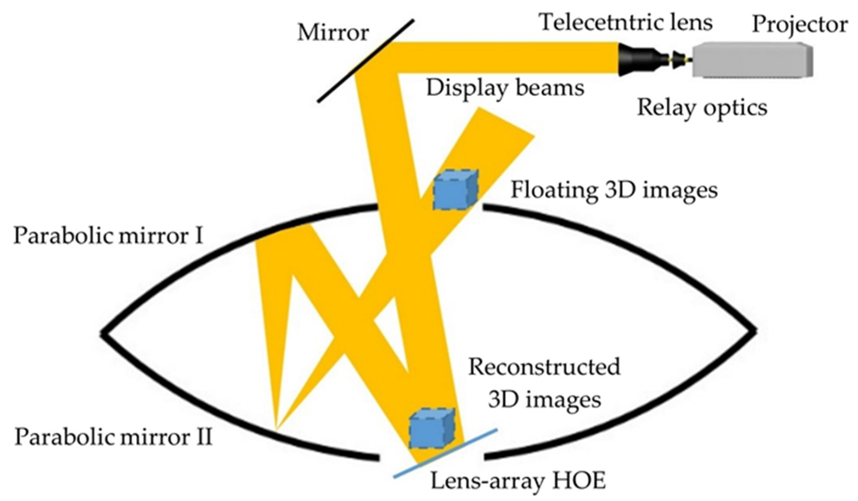
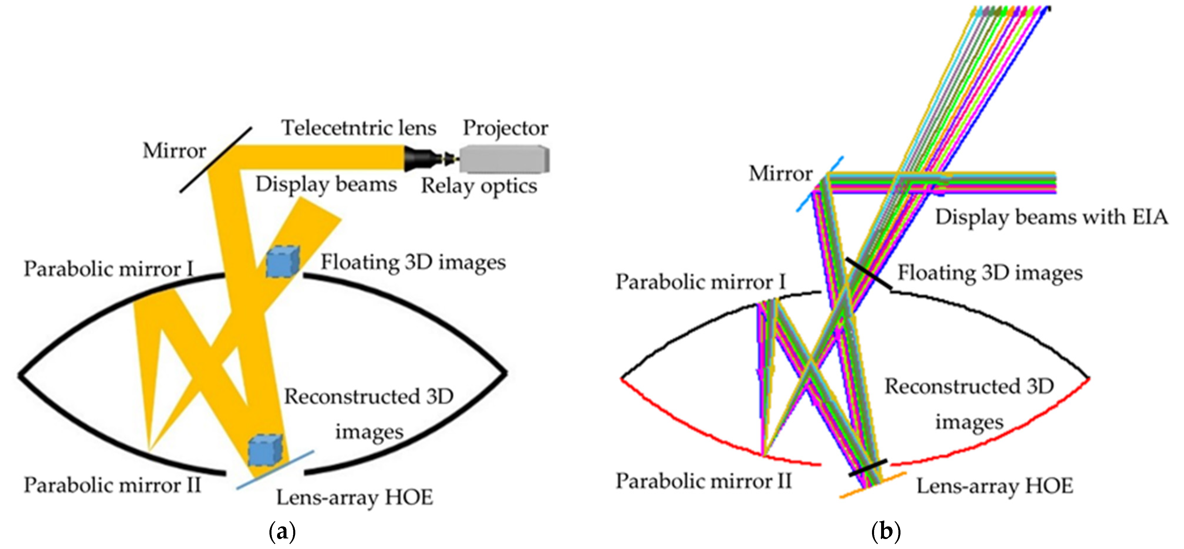
2.4. Imaging Principle of the Aerial Projection 3D Display

The imaging principle of the double parabolic mirrors is shown in Figure 5, which has been used for tabletop holographic display [20,21,22,23]. The double parabolic mirrors can output the 3D images at the bottom of parabolic mirror I to the top of parabolic mirror II. The distance between parabolic mirrors I and II is their focal length, and the imaging plane of the output images is at the top of parabolic mirror II; the output 3D images are inverted in the right and left spaces. Based on the imaging principle of the double parabolic mirrors, the aerial projection 3D display is designed, as shown in Figure 6. The aerial projection 3D display is composed of a projector, a lens-array HOE, and double parabolic mirrors, as shown in Figure 6a.
The ray-tracing analysis of the aerial projection 3D display is shown in Figure 6b. The display beams with EIA are projected onto the lens-array HOE, and the display beam satisfies the Bragg condition by the mirror. The image plane of integral imaging 3D image is reconstructed in front of the lens-array HOE. The reconstructed 3D image by the lens-array HOE is reflected by parabolic mirrors I and II, and then the aerial projection 3D image is presented in the air. The Bragg-unmatched light just passes through the lens-array HOE. Therefore, a 3D image is projected through the parabolic mirrors in the air and seems to float without any medium.

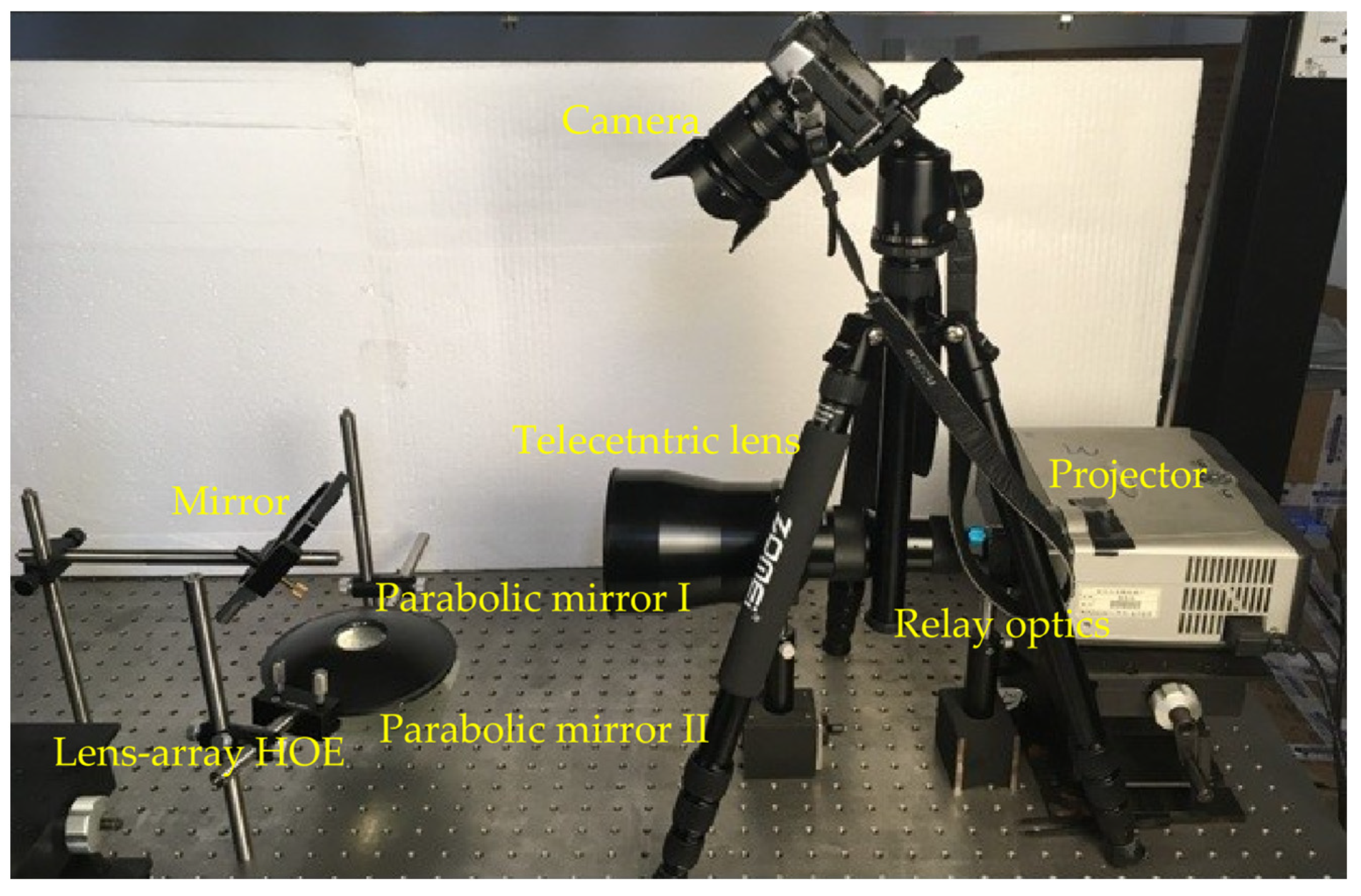
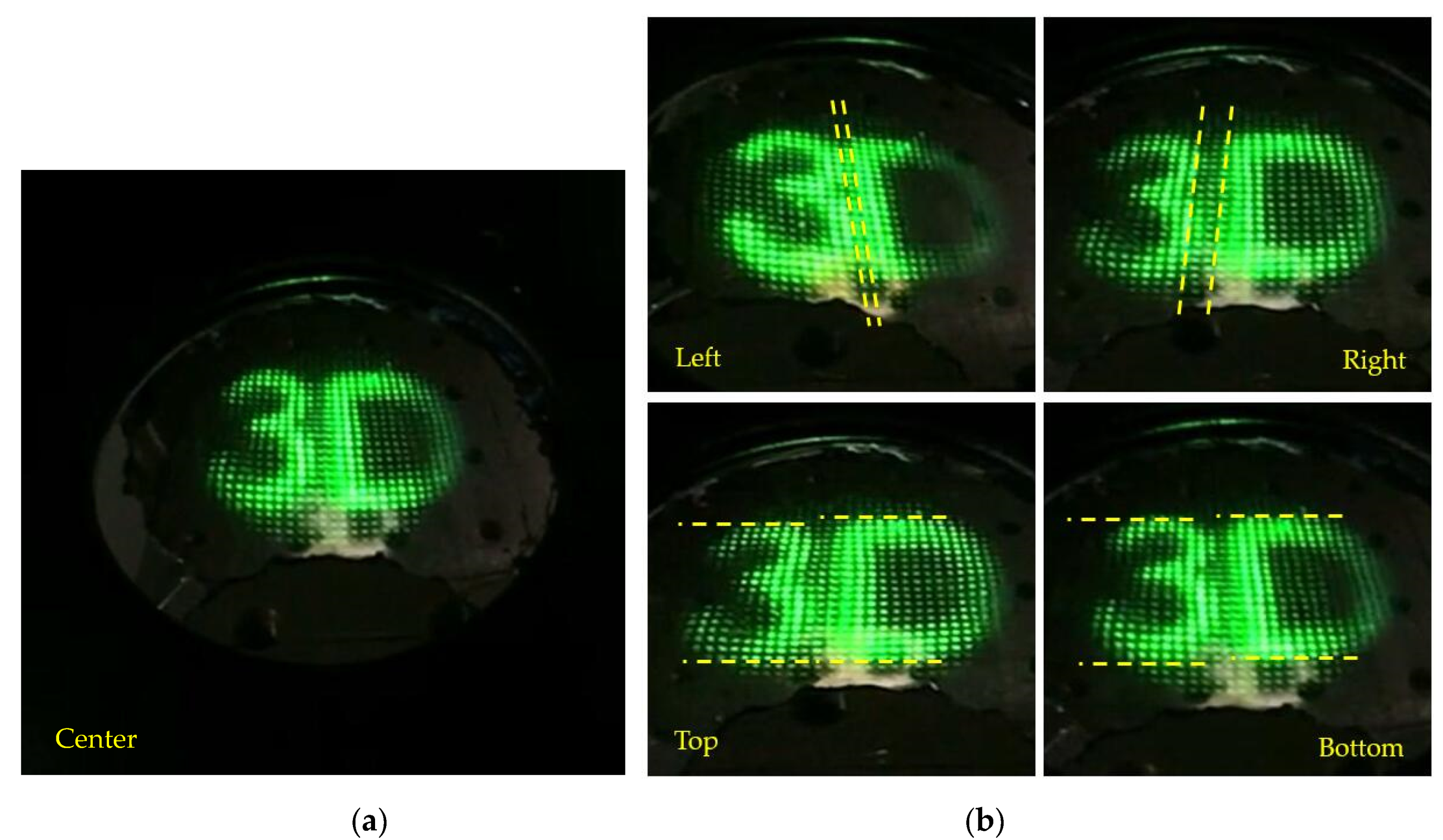
3. Experimental Results

The experimental setup of aerial projection 3D display based on lens-array HOE and parabolic mirrors is shown in Figure 7. The lens-array HOE was fabricated by the green-sensitive photopolymer material. The focal length of the elemental lens is 3.3 mm, and the pitch of the elemental lens is 1 mm. A monochrome lens-array HOE with a size of 50 mm × 50 mm was made. The diffraction efficiency of the lens-array HOE is 86%, and the transmittance of the lens-array HOE is 84%. The diameter and the height of each parabolic mirror are 150 mm, 25 mm, respectively. The inner diameter is 40 mm of the parabolic mirror. The projector (BenQ MX518F) was used to project the display beam with EIA information. The horizontal scanning frequency is 102 kHz, and the vertical scanning frequency is 120 Hz. The resolution of the projector is 1600 × 1200. The display beam projected by the projector is collimated through the relay optics and the telecentric lens. The display beam is reflected by the mirror and projected onto the lens-array HOE. When the display beam with EIA is projected onto the lens-array HOE, then the display beam satisfies the Bragg condition, and the 3D image can be reconstructed. When the reconstructed 3D image by the lens-array HOE is reflected by the parabolic mirrors, the aerial projection 3D image is presented in the air. The detailed parameters of the optical devices in the experiment are listed in Table 1.
The effective display size is only 35 mm × 35 mm. Only 35 × 35 micro-lenses were used to reconstruct 3D images. The resolution of the projector is 1600 × 1200. The 1200 pixels are divided into 35 micro-lens, and the number of pixels covered under each micro-lens is rounded to 34. The EIA was generated by computer computation. The 3D scene was built by 3D max software, the coordinates of “3” and “D” were (−12, −15, 15) and (12, 15, −15), and the font size of “3” and “D” was 40 mm. The distance between “3” and “D” was 30 mm, as shown in Figure 8. Then, the virtual camera array was used to acquire the parallax images of the 3D scene, and the number of cameras in the virtual camera is 34 × 34. Finally, the pixel mapping algorithm [38] was used to calculate the parallax image to obtain the EIA. Since the number of pixels covered under each micro-lens is 34 × 34, the resolution of EIA is 1190 × 1190, as shown in Figure 9. The pitch of the micro-lens is 1 mm, and its focal length is 3.3 mm. The viewing angle of 3D images in the experiment is about 10.2°. This is because the EIA and LAHOE cannot be accurately coupled, resulting in crosstalk in the reconstructed 3D images.
The experimental results of aerial projection 3D display based on lens-array HOE and parabolic mirrors are shown in Figure 10. The images of five viewpoints, including left, center, right, top, and bottom, were obtained. The 3D image is reconstructed in the air and can be seen as a floating image. When the display beams of EIA are projected on the lens-array HOE, the 3D image is reconstructed. The 3D image is reconstructed on a transparent display screen. Therefore, the 3D image is projected through the parabolic mirrors and seen as though floating in the air without any medium. The image of the center view of the aerial projection 3D display is shown in Figure 10a. By comparing the images of the left and right viewpoints, we find that the aerial projection 3D image has horizontal viewing parallax. By comparing the images of the top and bottom viewpoints, the vertical viewing parallax is found in the aerial projection 3D image, as shown in Figure 10b. The horizontal and vertical viewing parallaxes of the aerial projection 3D image are clearly shown in Visualization 1. The display size is 35 mm × 35 mm, so the resolution of the aerial projection 3D image is also 35 × 35. The experiment result confirms that the aerial projection 3D display in the air is realized.

4. Conclusions

We proposed an aerial projection 3D display based on integral imaging. It is composed of a projector, a lens-array HOE, and two parabolic mirrors. The lens-array HOE has the optical properties of a micro-lens array when the Bragg condition is satisfied. When the display beams with EIA are projected onto the lens-array HOE, the 3D image can be reconstructed. The two parabolic mirrors can project floating 3D images formed by the lens-array HOE. The prototype of the aerial projection 3D display was built. The experimental results prove that our proposed aerial projection 3D display is realized.

Author Contributions

Conceptualization, W.-X.Z. and H.-L.Z.; methodology, W.-X.Z. and H.-L.Z.; software, W.-X.Z.; H.-L.Z.; Q.-L.J.; H.D. and D.-H.L.; data curation and writing—original draft preparation, W.-X.Z. and H.-L.Z.; writing—review and editing, H.D. and D.-H.L. All authors have read and agreed to the published version of the manuscript.

Funding

This research is supported by the China Postdoctoral Science Foundation under Grant No.2021M690287, Applied Basic Research Program of Sichuan Province under Grant No. 2021YJ0094, and National Natural Science Foundation of China under Grant No.U20A20215.

Institutional Review Board Statement

Not applicable.

Informed Consent Statement

Not applicable.

Data Availability Statement

Data is contained within the article.

Conflicts of Interest

The authors declare no conflict of interest.

References

  1. Chou, P.Y.; Wu, J.Y.; Hsieh, P.Y.; Chen, C.H.; Yu, Z.S.; Tai, C.H.; Huang, Y.P. A toroidal-lens designed structure for static type table-top floating image system with horizontal parallax function. J. Soc. Inf. Disp. 2017, 25, 421–433. [Google Scholar] [CrossRef]
  2. Yoshida, S. 360-degree viewable glasses-free tabletop 3d display composed of conical screen and modular projector arrays. Opt. Express 2016, 24, 13194–13203. [Google Scholar] [CrossRef]
  3. Yoshida, S.; Yano, S.; Ando, H. Prototyping of glasses-free table-style 3D display for tabletop tasks. Sid Symp. Dig. Tech. Pap. 2010, 41, 211–214. [Google Scholar] [CrossRef]
  4. Xia, X.; Liu, X.; Li, H.; Zheng, Z.; Wang, H.; Peng, Y. A 360-degree floating 3d display based on light field regeneration. Opt. Express 2013, 21, 11237–11247. [Google Scholar] [CrossRef] [PubMed]
  5. Daisuke, M.; Kensuke, S.; Koji, S.; Kenji, M. Volumetric display system based on three-dimensional scanning of inclined optical image. Opt. Express 2006, 14, 12760–12769. [Google Scholar]
  6. Jia, J.; Chen, J.; Yao, J.; Chu, D. A scalable diffraction-based scanning 3D colour video display as demonstrated by using tiled gratings and a vertical diffuser. Sci. Rep. 2017, 7, 44656. [Google Scholar] [CrossRef] [PubMed] [Green Version]
  7. Su, C.; Zhou, X.; Li, H.; Yang, Q.; Liu, X. 360 Deg full-parallax light-field display using panoramic camera. Appl. Opt. 2016, 55, 4729–4735. [Google Scholar] [CrossRef]
  8. Takaki, Y.; Uchida, S. Table screen 360-degree three-dimensional display using a small array of high-speed projectors. Opt. Express 2012, 20, 8848–8861. [Google Scholar] [CrossRef]
  9. Maeda, Y.; Miyazaki, D.; Mukai, T.; Maekawa, S. Volumetric display using rotating prism sheets arranged in a symmetrical configuration. Opt. Express 2013, 21, 27074–27086. [Google Scholar] [CrossRef]
  10. Baasantseren, G.; Park, J.H.; Byeon, J.; Kwon, K.C.; Yoo, K.H.; Erdenebat, M.U. Integral-floating display with 360-degree horizontal viewing angle. J. Opt. Soc. Korea 2012, 16, 365–371. [Google Scholar]
  11. Hayan, K.; Keehoon, H.; Yongjun, L.; Hyon-Gon, C.; Jinwoong, K. Continuous viewing window formation for 360-degree holographic display. Digit. Hologr. Three-Dimens. Imaging 2017, W2A.22. [Google Scholar] [CrossRef]
  12. Kota, K.; Hasegawa, S.; Hayasaki, Y. Volumetric bubble display. Optica 2017, 4, 298–302. [Google Scholar]
  13. Kota, K.; Yoshio, H. Updatable bubble display. Digit. Hologr. Three-Dimens. Imaging 2017, M2B.4. [Google Scholar] [CrossRef]
  14. Patel, S.; Cao, J.; Lippert, A. A volumetric three-dimensional digital light photoactivatable dye display. Nat. Commun. 2017, 8, 15239. [Google Scholar] [CrossRef]
  15. Zhu, B.; Qian, B.; Liu, Y.; Xu, C.; Liu, C.; Chen, Q. A volumetric full-color display realized by frequency upconversion of a transparent composite incorporating dispersed nonlinear optical crystals. Npg Asia Mater. 2017, 9, E394. [Google Scholar] [CrossRef] [Green Version]
  16. Hirayama, R.; Naruse, M.; Nakayama, H.; Tate, N.; Shiraki, A.; Kakue, T. Design, implementation and characterization of a quantum-dot-based volumetric display. Sci. Rep. 2015, 5, 8472. [Google Scholar] [CrossRef] [Green Version]
  17. Asuka, Y.; Masataka, I.; Yoshihiro, K.; Osamu, O. 360-degree fog projection interactive display. ACM SIGGRAPH Asia Emerg. Technol. 2011, 19. [Google Scholar] [CrossRef]
  18. Sand, A.; Rakkolainen, I. A hand-held immaterial volumetric display. Stereoscopic Displays and Applications XXV. Int. Soc. Opt. Photonics 2014, 9011, 90110Q-7. [Google Scholar]
  19. Barnum, P.C.; Narasimhan, S.G.; Kanade, T. A multi-layered display with water drops. ACM Trans. Graph. 2010, 29, 1–7. [Google Scholar] [CrossRef]
  20. Kim, J.; Lim, Y.; Hong, K.; Chang, E.; Choo, H. 360-degree tabletop color holographic display. Digit. Hologr. Three-Dimens. Imaging 2017, W3A.1. [Google Scholar] [CrossRef]
  21. Lim, Y.; Hong, K.; Kim, H.; Kim, H.E.; Hahn, J. 360-degree tabletop electronic holographic display. Opt. Express 2016, 24, 24999–25009. [Google Scholar] [CrossRef] [Green Version]
  22. Kakue, T.; Nishitsuji, T.; Kawashima, T.; Suzuki, K.; Shimobaba, T.; Ito, T. Aerial projection of three-dimensional motion pictures by electro-holography and parabolic mirrors. Sci. Rep. 2015, 5, 11750. [Google Scholar] [CrossRef] [PubMed] [Green Version]
  23. Onural, L. Design of a 360-degree holographic 3D video display using commonly available display panels and a paraboloid mirror. SPIE OPTO 2017, 101260I. [Google Scholar]
  24. Hsu, C.H.; Cheng, W.H.; Hua, K.L. Holotabletop: An anamorphic illusion interactive holographic-like tabletop system. Multimed. Tools Appl. 2017, 76, 9245–9264. [Google Scholar] [CrossRef]
  25. Lim, Y.; Hong, K.; Kim, H.; Choo, H.; Park, M.; Kim, J. An optical method for compensating phase discontinuity in a 360-degree viewable tabletop digital holographic display system. SPIE Digit. Opt. Technol. 2017, 10335, 1033510. [Google Scholar]
  26. Chang, E.Y.; Choi, J.; Lee, S.; Kwon, S.; Yoo, J.; Choo, H.G. 360-degree Color Hologram Generation for Real 3-D Object. Digit. Hologr. Three-Dimens. Imaging 2017, W2A.28. [Google Scholar] [CrossRef]
  27. Zhang, H.; Deng, H.; Yu, W.; He, M.; Li, D.; Wang, Q. Tabletop augmented reality 3d display system based on integral imaging. J. Opt. Soc. Am. B 2017, 34, B16. [Google Scholar] [CrossRef]
  28. Shih, C.; Wang, J.; Ting, C.; Huang, Y. Floating 3d image for high resolution portable device using integral photography theory. SID Symp. Dig. Tech. Pap. 2015, 46, 354–357. [Google Scholar] [CrossRef]
  29. Miyazaki, D.; Maeda, Y. Floating three-dimensional display viewable from 360 degrees. SPIE-Int. Soc. Opt. Eng. 2012, 8288, 822881H. [Google Scholar]
  30. Hong, J.Y.; Yeom, J.; Jeong, Y.; Kim, J.; Park, S.G.; Hong, K. Table-top display using integral floating display. In Proceedings of the 2013 International Conference on 3D Imaging, Liege, Belgium, 3–5 December 2013; pp. 1–5. [Google Scholar]
  31. Zhao, D.; Su, B.; Chen, G.; Liao, H. 360-degree viewable floating autostereoscopic display using integral photography and multiple semitransparent mirrors. Opt. Express 2015, 23, 9812–9823. [Google Scholar] [CrossRef]
  32. Zhao, D.; Ma, L.; Ma, C.; Tang, J.; Liao, H. Floating autostereoscopic 3D display with multidimensional images for tele surgical visualization. Int. J. Comput. Assist. Radiol. Surg. 2016, 11, 207–215. [Google Scholar] [CrossRef]
  33. Wang, Z.; Wang, A.; Ma, X.; Liu, B.; Ma, F.; Ming, H. Integral floating 3d display using two retro-reflector arrays. IEEE Photonics J. 2017, 9, 7000108. [Google Scholar]
  34. Yoshimoto, K.; Takahashi, H.; Yamada, K. 360-degree three-dimensional flat panel display using holographic optical elements. SPIE/IST Electron. Imaging 2015, 9391, 93910M. [Google Scholar]
  35. Yu, X.; Sang, X.; Gao, X.; Yang, S.; Liu, B.; Chen, D. Floating aerial 3d display based on the freeform-mirror and the improved integral imaging system. Opt. Commun. 2018, 423, 162–166. [Google Scholar] [CrossRef]
  36. Wang, Y.; Ren, Z.Q.; Zhang, L.; Li, D.H.; Li, X.W. 3D image hiding using deep demosaicking and computational integral imaging. Opt. Lasers Eng. 2022, 148, 106772. [Google Scholar] [CrossRef]
  37. He, M.Y.; Zhang, H.L.; Deng, H.; Li, D.H.; Wang, Q.H. Dual-view-zone tabletop 3D display system based on integral imaging. Appl. Opt. 2018, 57, 952–958. [Google Scholar] [CrossRef]
  38. Li, S.L.; Wang, Q.H.; Xiong, Z.L.; Deng, H.; Ji, C.C. Multiple orthographic frustum combing for real-time computer generated integral imaging system. J. Disp. Technol. 2014, 10, 704–709. [Google Scholar] [CrossRef]
Figure 1. Principle diagram of the aerial projection 3D display based on a lens-array HOE and a pair of parabolic mirrors.
Photonics 08 00381 g001
Figure 2. Fabrication principle of the lens-array HOE.
Photonics 08 00381 g002
Figure 3. Reconstruction principle of a 3D image using the lens-array HOE.
Photonics 08 00381 g003
Figure 4. (a) The track of the light rays that focuses on the focus; (b) the track of the light rays reflected from the focus; (c) the track of the light rays from a source on the right side focusing on the left.
Photonics 08 00381 g004
Figure 5. The imaging principle of the parabolic mirrors: (a) the red ball reconstructed in the right side of parabolic mirror II; (b) the green ball reconstructed in the center of parabolic mirror II; (c) the blue ball reconstructed in the right side of parabolic mirror II; (d) the reconstructed image inverted in the left and right spaces.
Photonics 08 00381 g005
Figure 6. (a) The imaging principle of the aerial projection 3D display; (b) the simulation results of ray tracing for aerial projection 3D display.
Photonics 08 00381 g006
Figure 7. Experimental setup of the aerial projection 3D display based on lens-array HOE and parabolic mirrors.
Photonics 08 00381 g007
Figure 8. Schematic diagram of EIA acquisition: (a) side view and (b) top plan view.
Photonics 08 00381 g008
Figure 9. Elemental image array for reconstruction 3D image.
Photonics 08 00381 g009
Figure 10. Experimental results of aerial projection 3D display based on lens-array HOE and parabolic mirrors (a) in the center and (b) in the left, right, top, and bottom (see Visualization 1).
Photonics 08 00381 g010
Table 1. Parameters of the optical devices in the experiments.
ComponentsParametersValues
Photopolymer materialThickness15 ± 1 μm
Resolutionline/mm
Sensitive wavelength532 nm
Sensitivity10 mJ/cm2
Refractive index modulation>0.02
Averaged Refractive Index1.47
Lens-arrayPitch1 mm
Focal length3.3 mm
ProjectorModelMX518 F
Resolution1600 × 1200
Parabolic mirrorDiameter150 mm
Height25 mm
Inner diameter40 mm
Publisher’s Note: MDPI stays neutral with regard to jurisdictional claims in published maps and institutional affiliations.

