Article

Multi-View 3D Integral Imaging Systems Using Projectors and Mobile Devices

1
Scientific and Technological Center of Unique Instrumentation of the Russian Academy of Sciences, 15 Butlerova Str., 117342 Moscow, Russia
2
All-Russia Research Institute of Physical-Technical and Radio Measurements (VNIIFTRI), 141570 Moscow, Russia
*
Author to whom correspondence should be addressed.
Photonics 2021, 8(8), 331; https://doi.org/10.3390/photonics8080331
Submission received: 10 July 2021 / Revised: 8 August 2021 / Accepted: 10 August 2021 / Published: 13 August 2021
(This article belongs to the Special Issue Holography)

Abstract

:
Glassless 3D displays using projectors and mobile phones based on integral imaging technology have been developed. Three-dimensional image files are created from the 2D images captured by a conventional camera. Large size 3D images using four HD and Ultra HD 4K projectors are created with a viewing angle of 35 degrees and a large depth. Three-dimensional images are demonstrated using optimized lenticular lenses and mobile smartphones, such as LG and Samsung with resolution 2560 × 1440, and 4K Sony with resolution 3840 × 2160.

1. Introduction

The real 3D display systems of various types, including integral imaging and holographic and multi-view methods are available at present [1,2,3]. In [4], a detailed overview of some studies in the field of integral imaging, including sensing of 3D scenes, processing of captured information, and 3D display and visualization of information is presented. Integral imaging has significant advantages over other methods, namely, the absence of a complex mechanical and optical system, the use of inexpensive materials in production, and the possibility of simultaneous vision by several viewers. However, there are limitations on the current display methods. They consist of a small viewing angle, a small depth of the image, and the presence of sharp edges when switching between adjacent viewing zones.
Multi-projection systems can be used to increase the resolution and the image size [5,6,7,8,9]. In [10], a multi-view multi-projection system using multiple flat-panel 3D displays was proposed. In [11], a 14.4-inch large-screen 3D display system using the four projectors was realized. In [12], a multi-projection 3D display using 300 projectors was developed. In [13], two micro-lens arrays (MLAs) with different focal lengths for capturing and displaying, respectively, are proposed to increase the resolution. In [14,15] preliminary designs of the 3D systems based on multi-projectors and mobile phones were carried out. In [16], multiple projectors were used to enlarge the viewing zone of an integral 3D image. Three-dimensional display system using a conventional mobile phone is analyzed in [17]. In [18], 3D integral imaging display with a smartphone was demonstrated. Currently, new types of high-resolution projectors and mobile phones have appeared on the market, including ultra-HD 4K projectors, so it is of practical interest to use them to increase the resolution, viewing angle, depth, and image size.
In this paper, the multi-view 3D display systems using the HD 4K projectors and mobile phones are developed. It is shown that a simple algorithm can be applied to create 3D image files when a rotating platform is used to capture images. Three-dimensional images are demonstrated using optimized lenticular lens sheets and mobile smartphones. Compared to a system of four projectors, here we used an ultra HD 4K projector instead of high-definition projectors. This allowed us to demonstrate 4K 3D images without having to solve the problems of boundary and colors alignment. A new design of the display screen was proposed and 3D images were demonstrated using mobile smartphone devices, which allowed us to solve the problem of aligning the display pixels with an array of lenses. Next-generation 3D display technologies are discussed in the Discussion section.

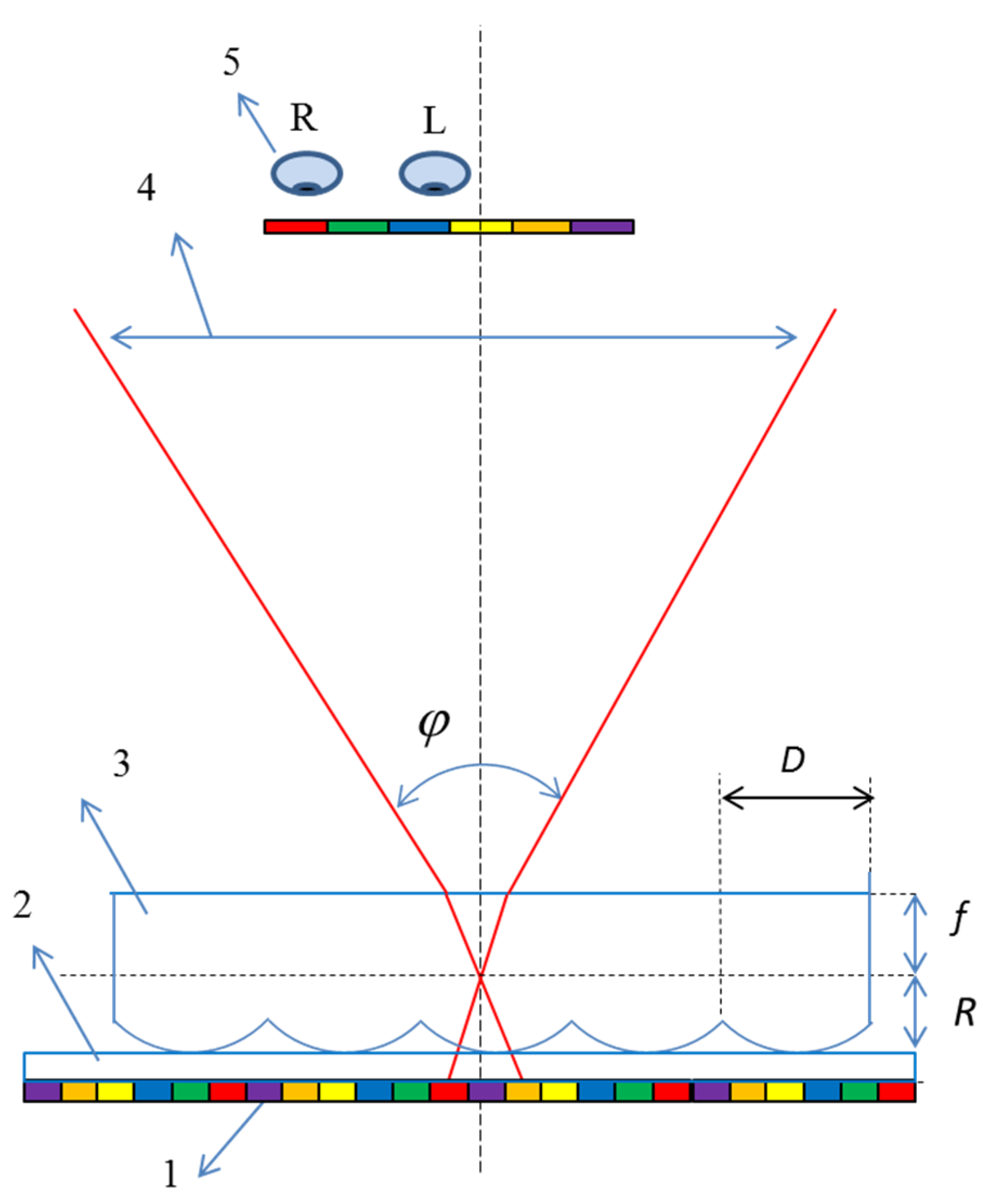
2. Multi-View Projector-Based Display System

The principle of autostereoscopic 3D displays is that 3D optics controls the direction of the light rays of each pixel in such a way that different views are projected onto our left and right eyes. Usually, a lenticular array of lenses and parallax or slit barriers are used to control the light rays from pixels in displays.
Our multi-view system consists of a projector, diffuser layer, and lenticular lens (Figure 1). The viewpoints for observers are created by the light rays from a display element of the projector which are incident on a screen.
The pitch size of the lenticular lens array and the focal length of the elemental lens define the viewing angle:
φ = 2 arctan ( D 2 f ) = 2 arctan ( D 2 ( h R ) )
where D is the pitch of the lens array, h = f + R is the total thickness of the lenticular layer, R is the curvature radius of the individual lens in the lenticular layer, and f is the focal length.
The generation of an optical field on the display screen can be described by equations based on both geometric optics and wave optics approaches [19,20,21]. In [21], an analysis of the Wigner distribution function for a 3D-projection-type display is proposed. Recently, the diffraction of partially coherent light beams by microlens array was studied in [22]. Here we mainly focus on the experimental demonstration of 3D images using projectors and mobile devices.

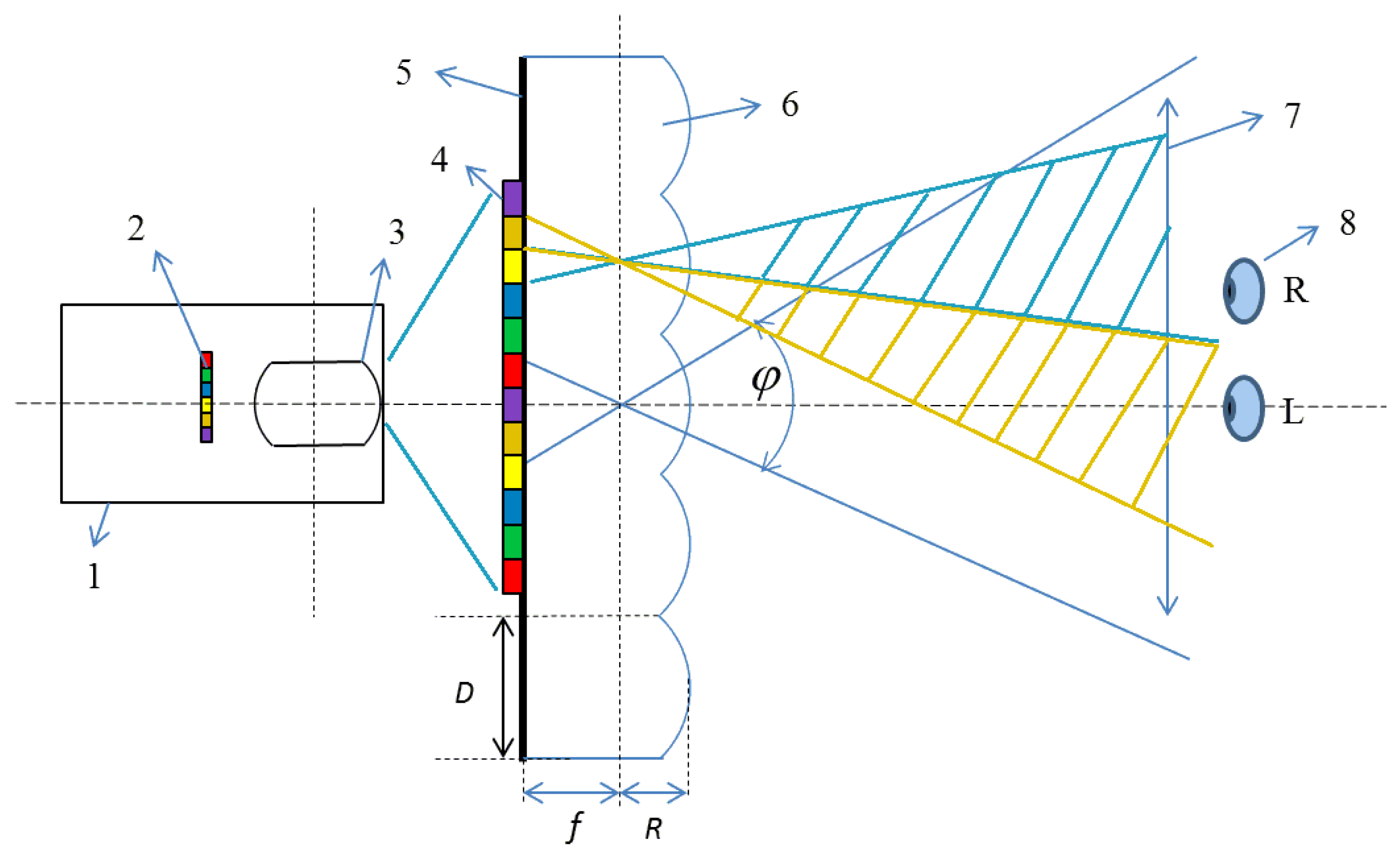
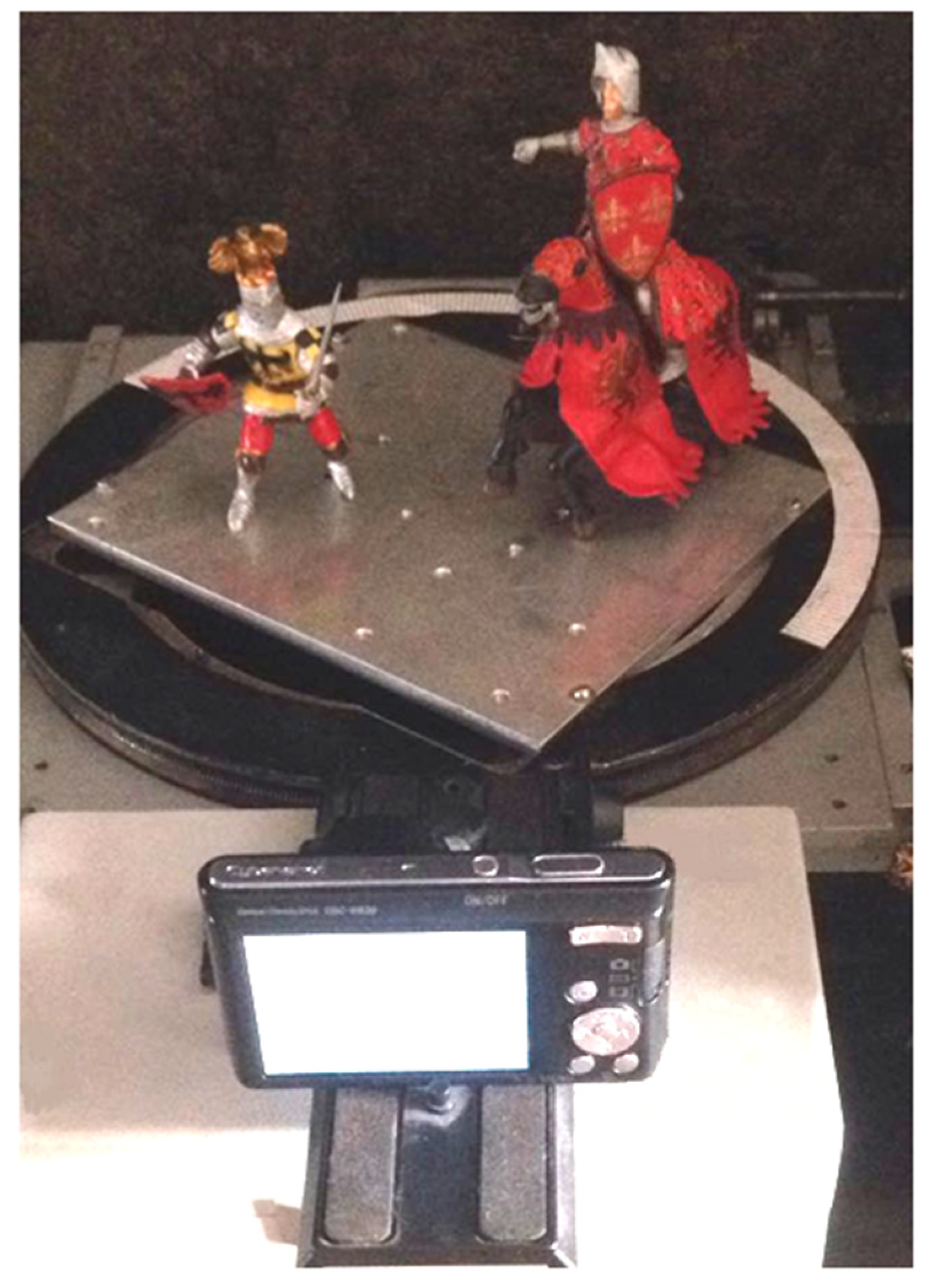
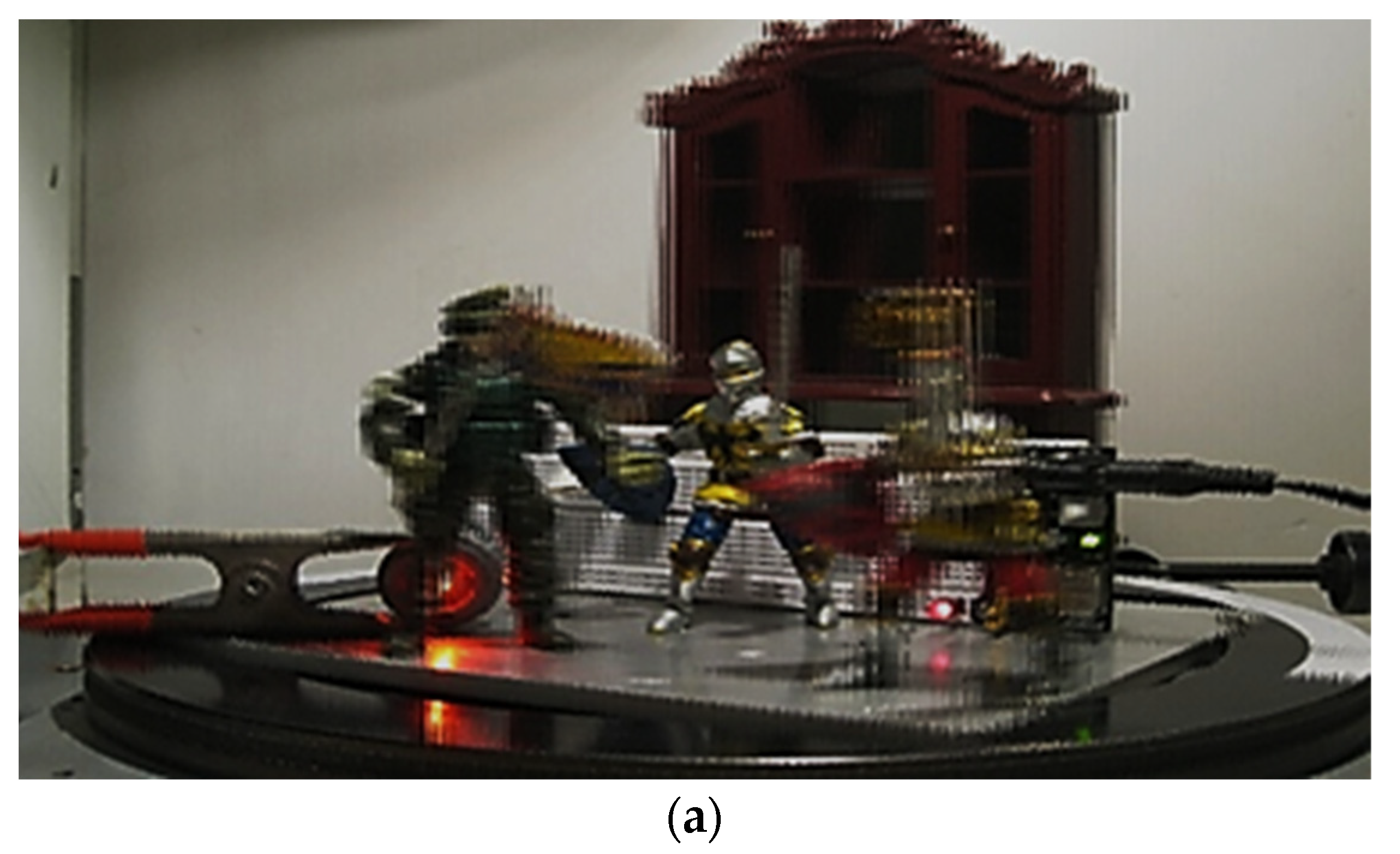
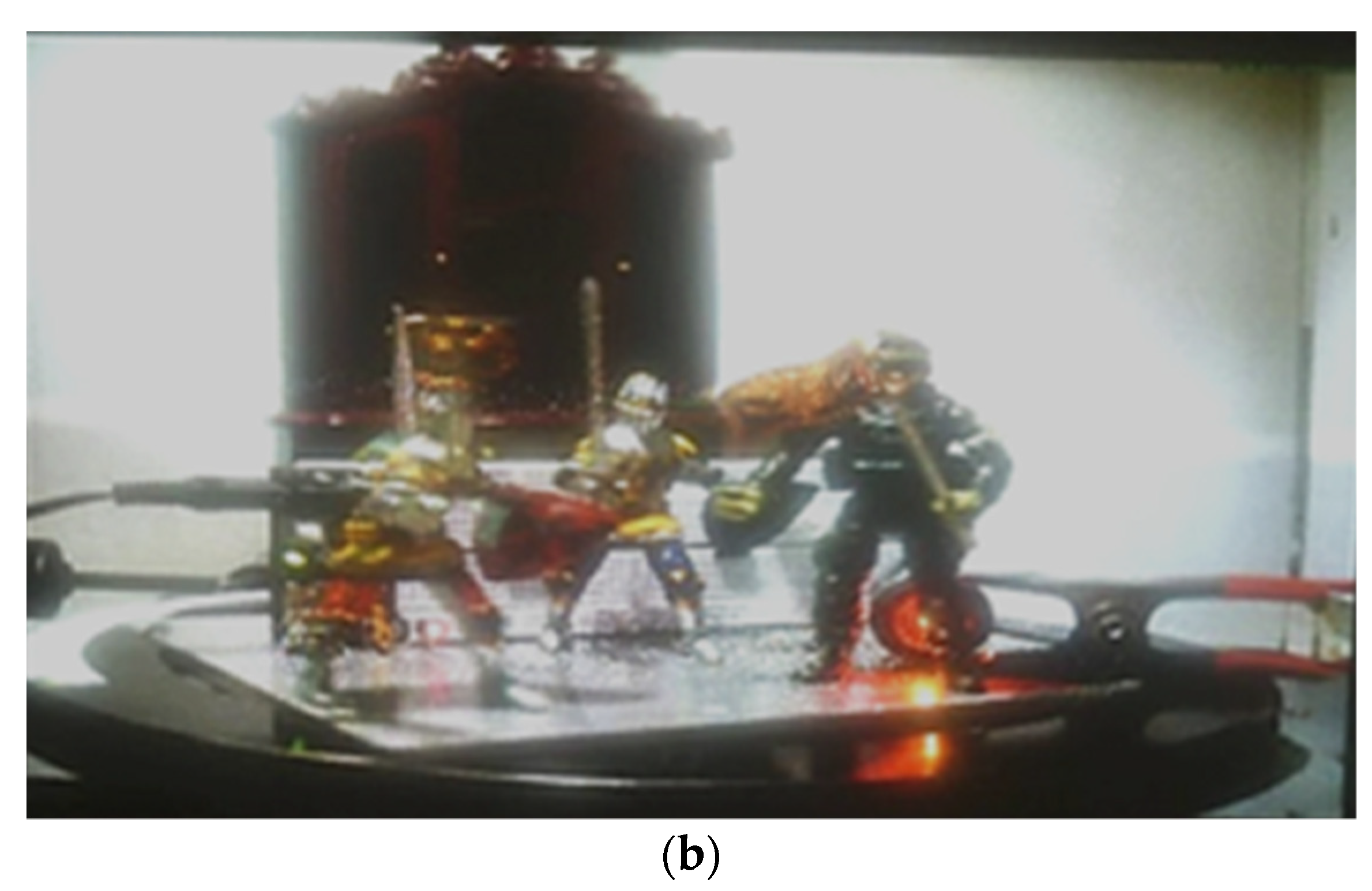
2.1. Image Capturing of 3D Object

The disadvantage of the integral imaging method [1,2] for capturing is the small image depth. Here we captured the object from different angles using a rotating table and a conventional camera. This allowed us to obtain a higher image depth (Figure 2). We shot 2D images using a rotating table at different viewing angles with an interval of 1 or 2 degrees. Capturing with a conventional camera and a rotating table simplifies the mathematical model for creating 3D image files. There is an alternative method based on the computational generation of the 3D image files. However, this requires the use of the complex geometrical transformations of the 2D images.
The rotation angles of the camera can affect the 3D image depth. When the angle between two adjacent 2D images increases, the depth of the 3D image also increases. However, this leads to the decrease of the angular resolution of the image. To obtain images, a Sony w830 camera was used, the CCD matrix of which has a resolution of 5152 × 3864 with a pixel size of 1.2 microns. The focal length was 25 mm with a viewing angle of 80 degrees. The camera was located at a distance of 30 cm from the object. With the help of a turntable, the object was captured through 1 or 2 degrees, and the necessary number of images (8–15) was obtained to create a 3D image file.

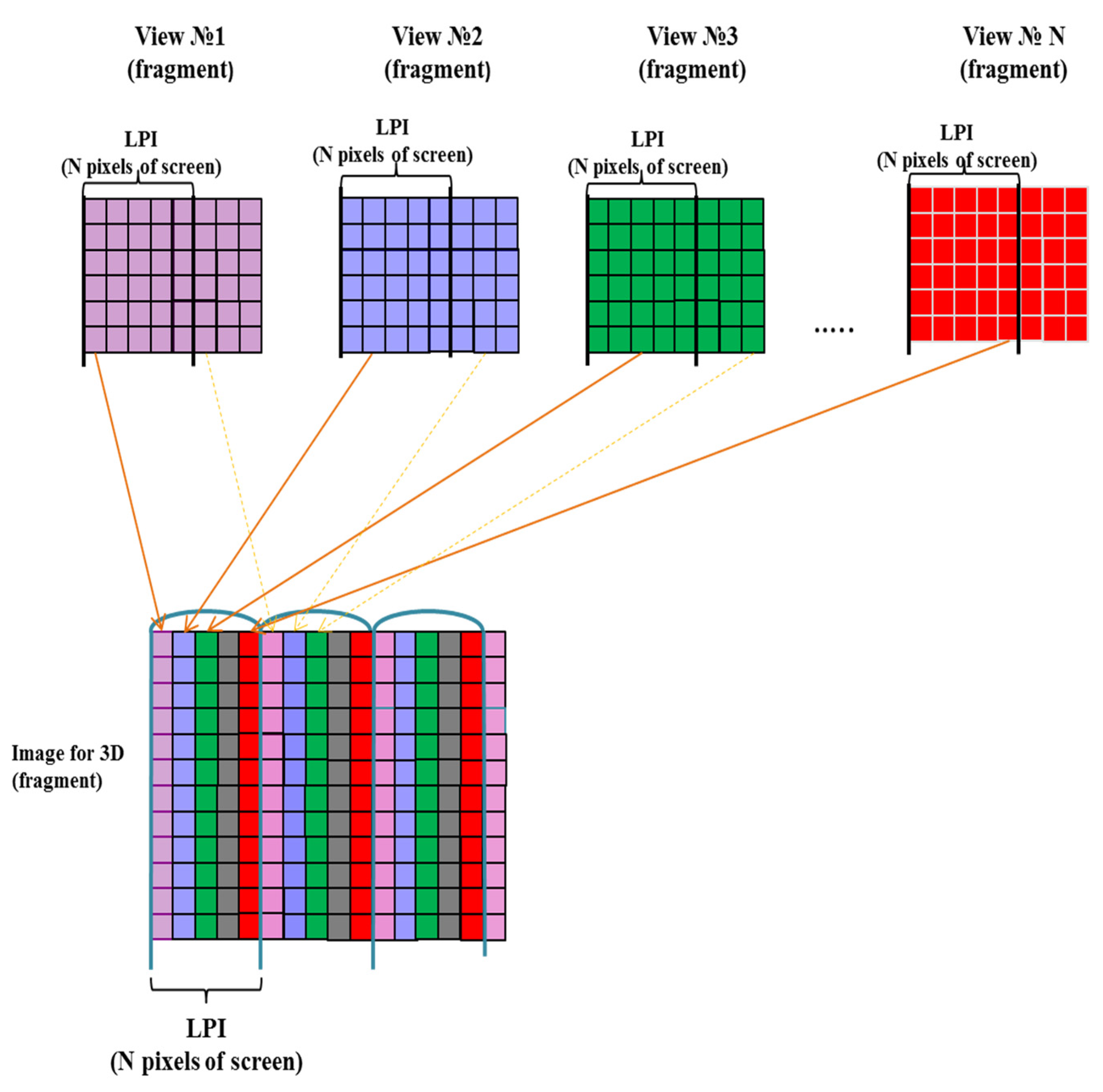
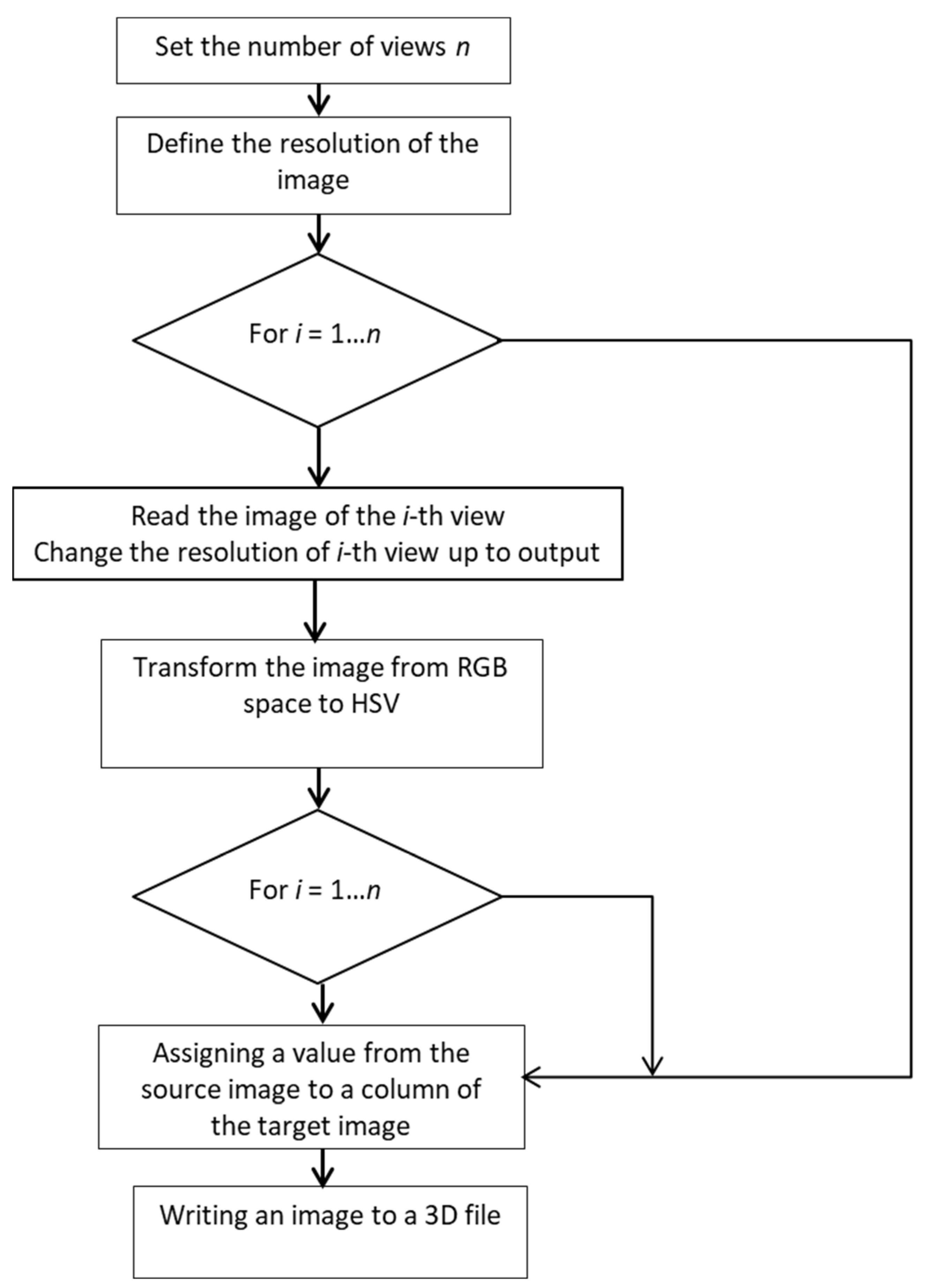
2.2. D Image Files Creation

A schematic representation of the method for creating a 3D image file is shown in Figure 3. First, we need to prepare the original 2D images, the number of which is equal to the number of views. The original image is converted into a matrix with a specified number of pixels (Figure 3).
A part of each view is placed under each lens of the lenticular sheet to be able to see each view from a strictly defined angle. One strip from each view is placed under one vertical cylindrical lens, i.e., the vertical columns of pixels are aligned with the lenticular lenses. A column of pixels is assigned to one view for each of the N columns. More detailed description is presented in [15]. Codes for integration of images captured at different angles into one common 3D file are created in MatLab. A flowchart of the 3D image file creation is shown in Figure 4.
An example of the created 3D image file is shown in Figure 5a. Note that the vertical stripes are observed in the image. In Figure 5b the 3D image with lens array is shown. It is seen that the quality of image with lens array is higher.

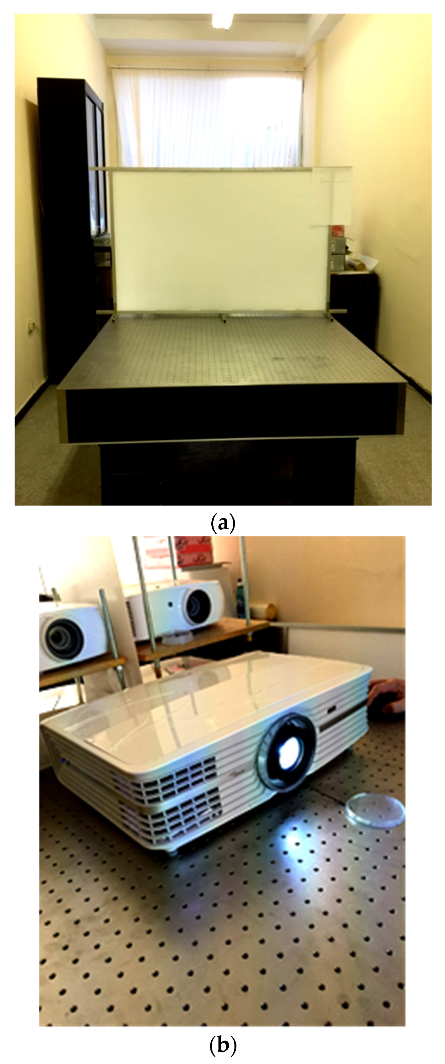
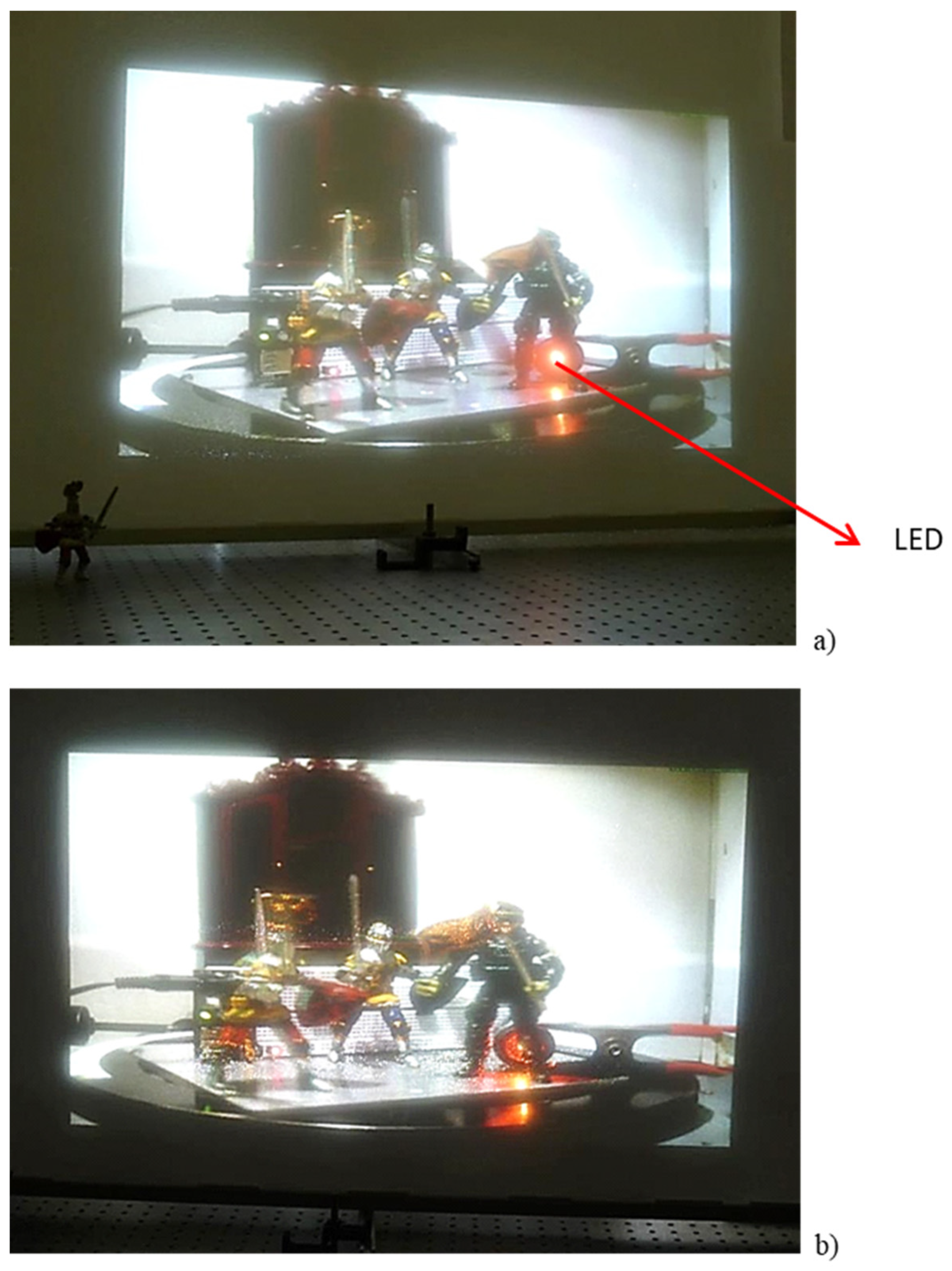
2.3. Experimental System

The designed and constructed experimental display system is shown in Figure 6. Four full HD digital light processing (DLP) projectors with a 4K equivalent resolution were arranged in a 2 × 2 array. The display screen consists of a diffuser layer scattering uniformly and a lenticular sheet. The projectors and screen are adjusted on the optical table with a simple pitch test method. Gap distance between the projectors and screen depends on the pitch size of the lenticular lens and number of viewpoints. This distance is equal to 50 cm for the lenticular sheet with the pitch D = 1.27 mm (20 lpi) and number of viewpoints N = 6.
Images were corrected by the image processing to compensate for the increased brightness at the intersection of the images of adjacent projectors. The brightness of the entire image can be smoothed by reducing the brightness of the pixels corresponding to the overlapping parts. Detailed description of a system of four projectors is presented in [15]. Here we use an Ultra HD 4K projector with a resolution of 3840 × 2160 pixels. Unlike using four HD projectors, here we do not need to solve the problems of alignment of boundaries and colors [15].
Three-dimensional image size depends on the display matrix of the projector and the number of view N. The image size in the horizontal direction can be estimated as
      L = n N D
where N is the view number, n is the pixels number of the projector’s display matrix, and D is the pitch size of the lenticular sheet.
It follows from (2), that the image size L = 542 mm for the number of views N = 9 and L = 406 mm when N = 12 for the lenticular sheet with 20 lpi and projector’s display matrix with n = 3840.
The distance between the screen and projector is determined by the parameters of the projector, lenticular sheet, and view numbers. Three-dimensional images with a viewing angle of 35 degrees and a large depth are demonstrated for the lenticular array parameters presented in Table 1.

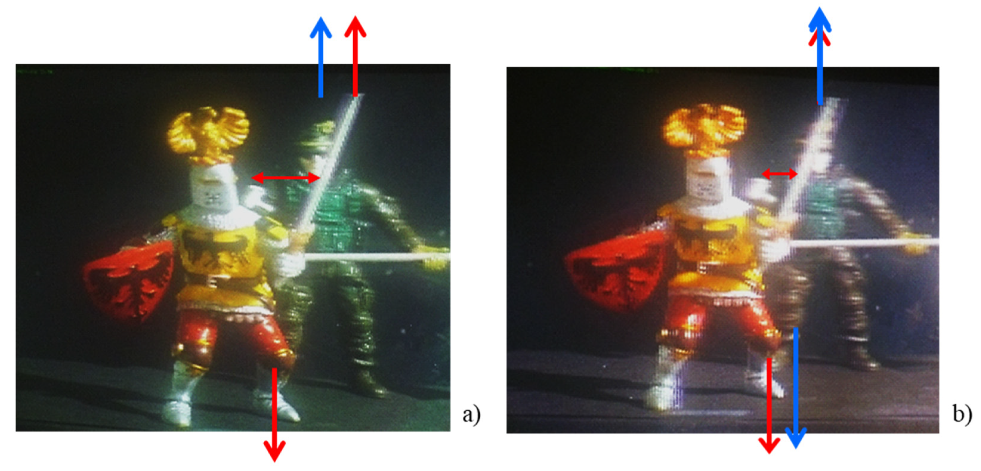
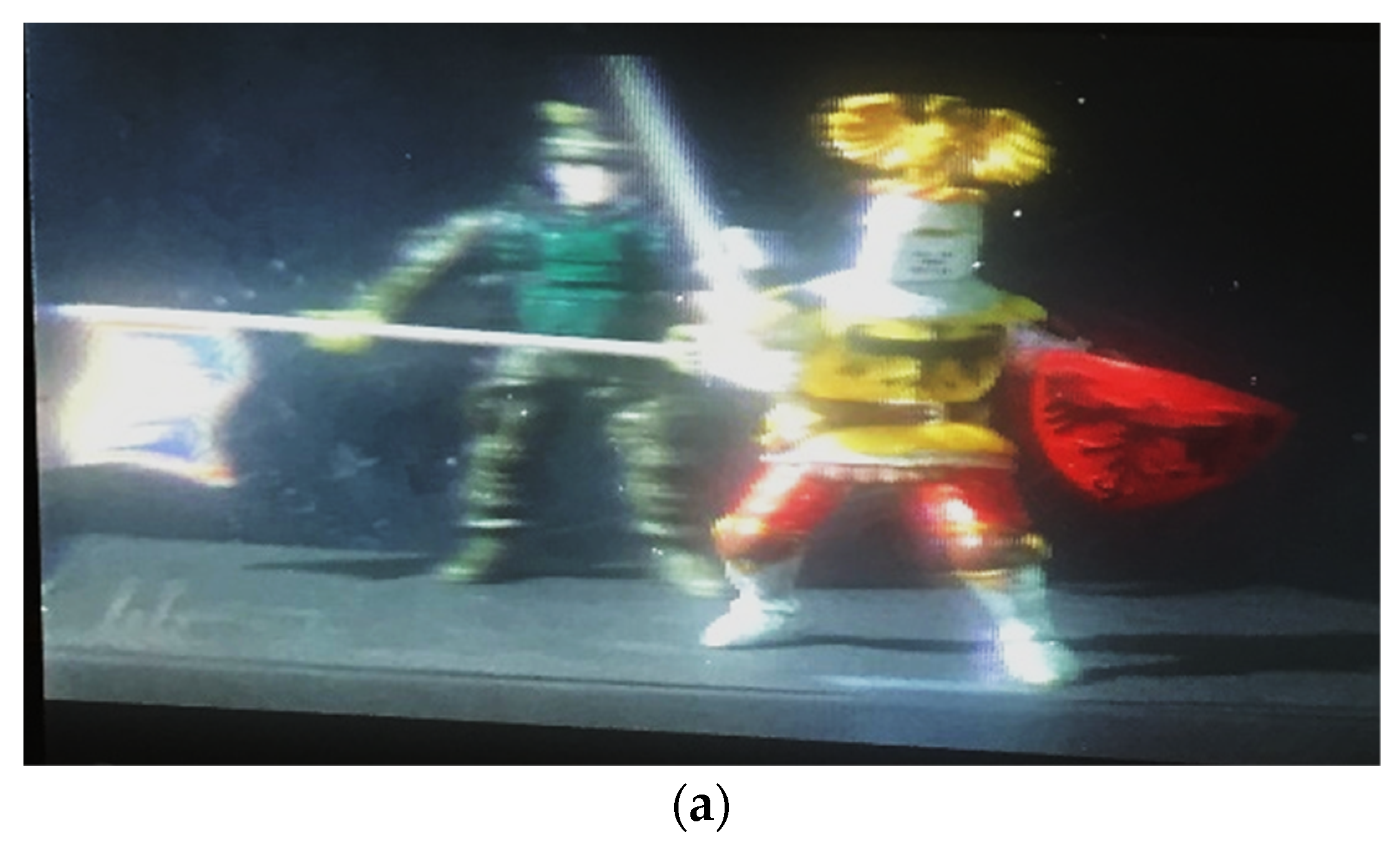
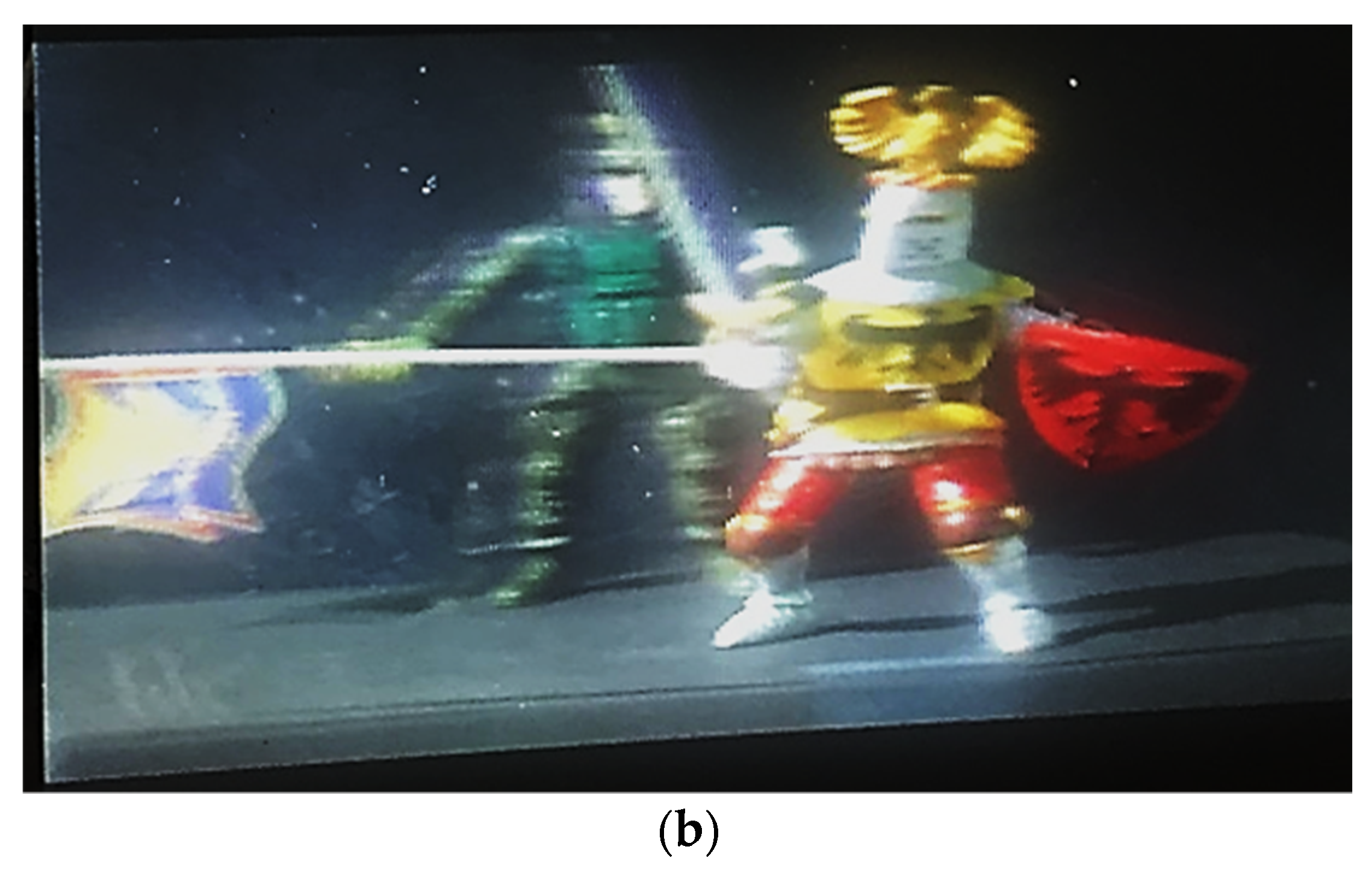
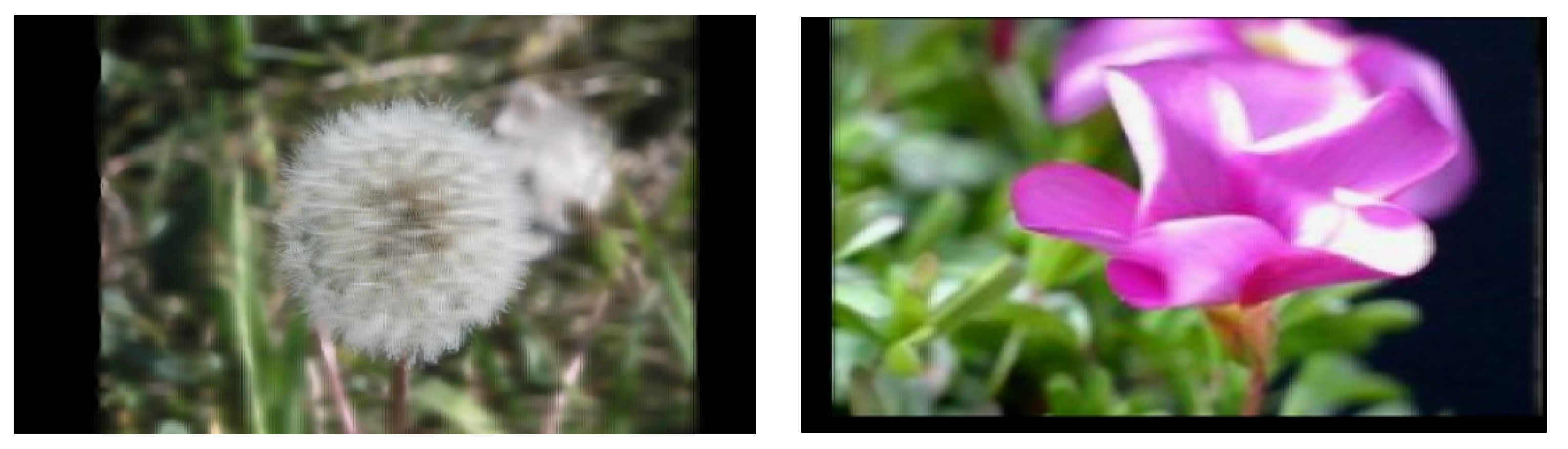
3. 3D Image Displaying: Experimental Results

In Figure 7, the images using the BENQ full HD projector with resolution 1920 × 1080 pixels from different viewing directions are presented. It is seen that the objects become visible at a given viewing angle which are hidden from view in another viewing angle.
In Figure 8, the images of 34-inches size obtained using four full HD projectors from different viewing angles are shown. It follows from the experiments that the viewing angle increases when the depth range decreases. The lenticular arrays with aspheric surface profiles should be used in order to increase the image depth.
In Figure 9, images at different observation angles using Ultra HD 4K projector with resolution 3840 × 2160 pixels are presented. Unlike the use of four HD projectors, here we do not have to solve problems of alignment of boundaries and colors.

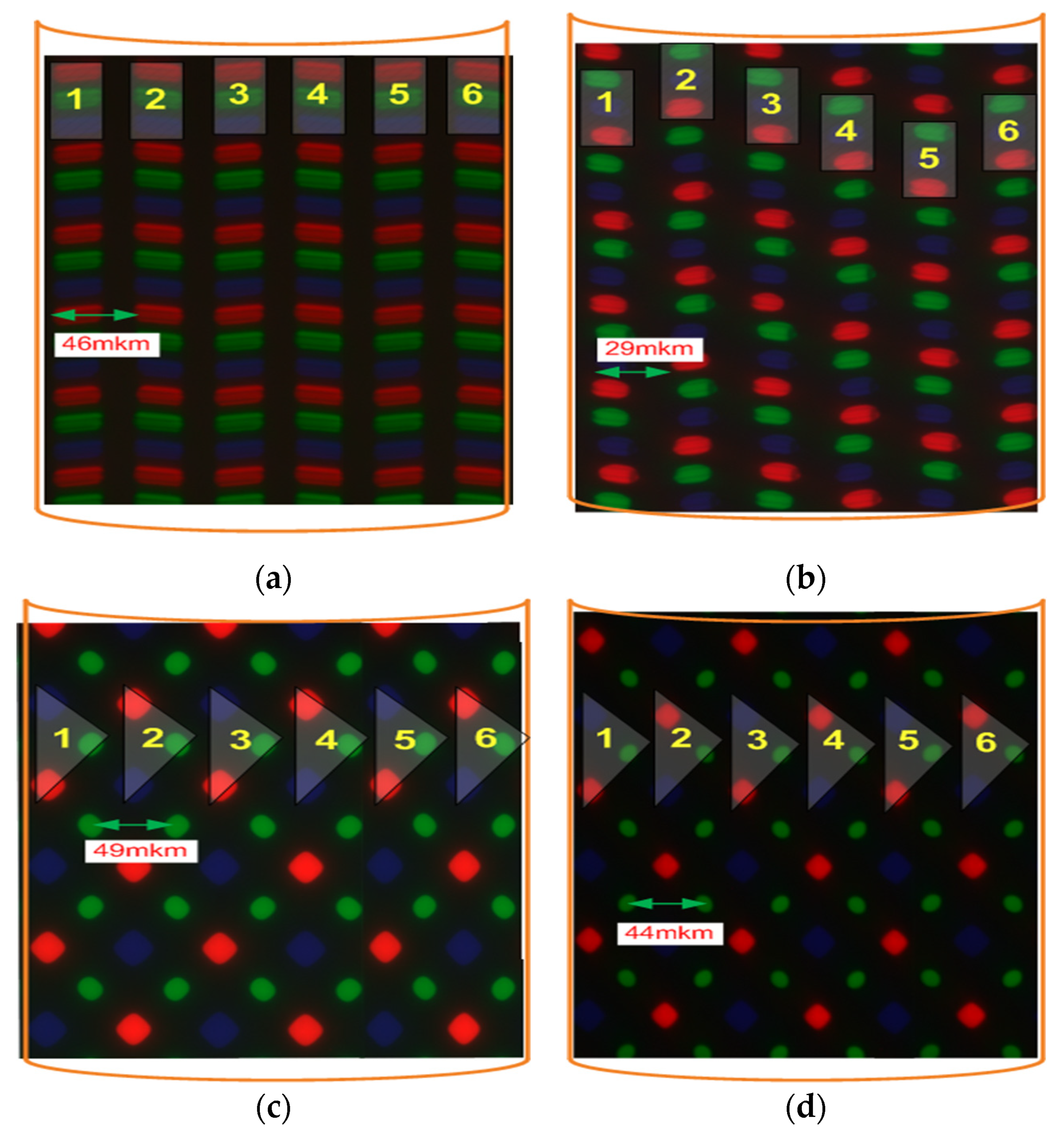
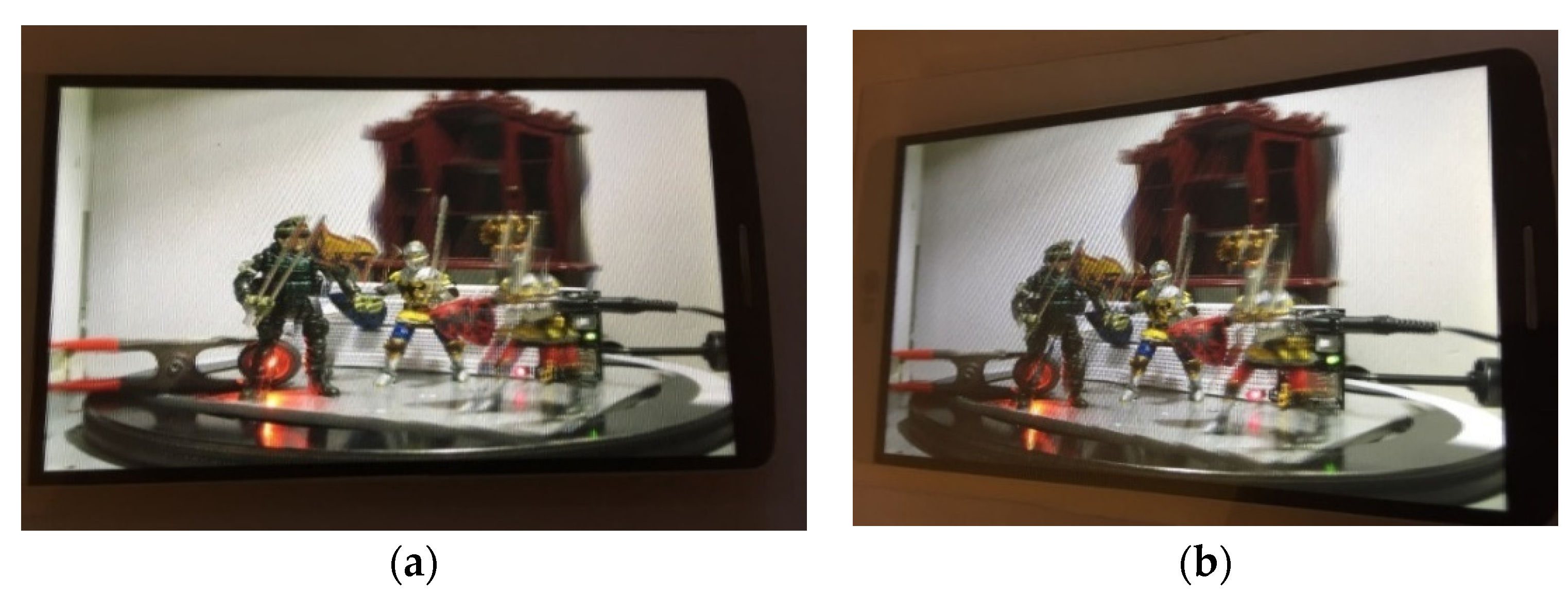
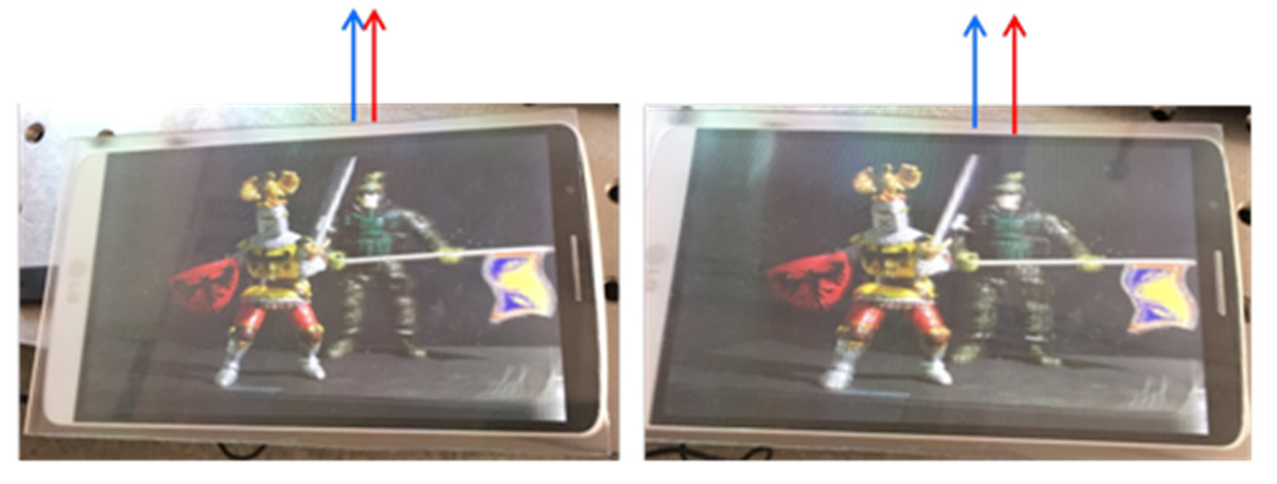
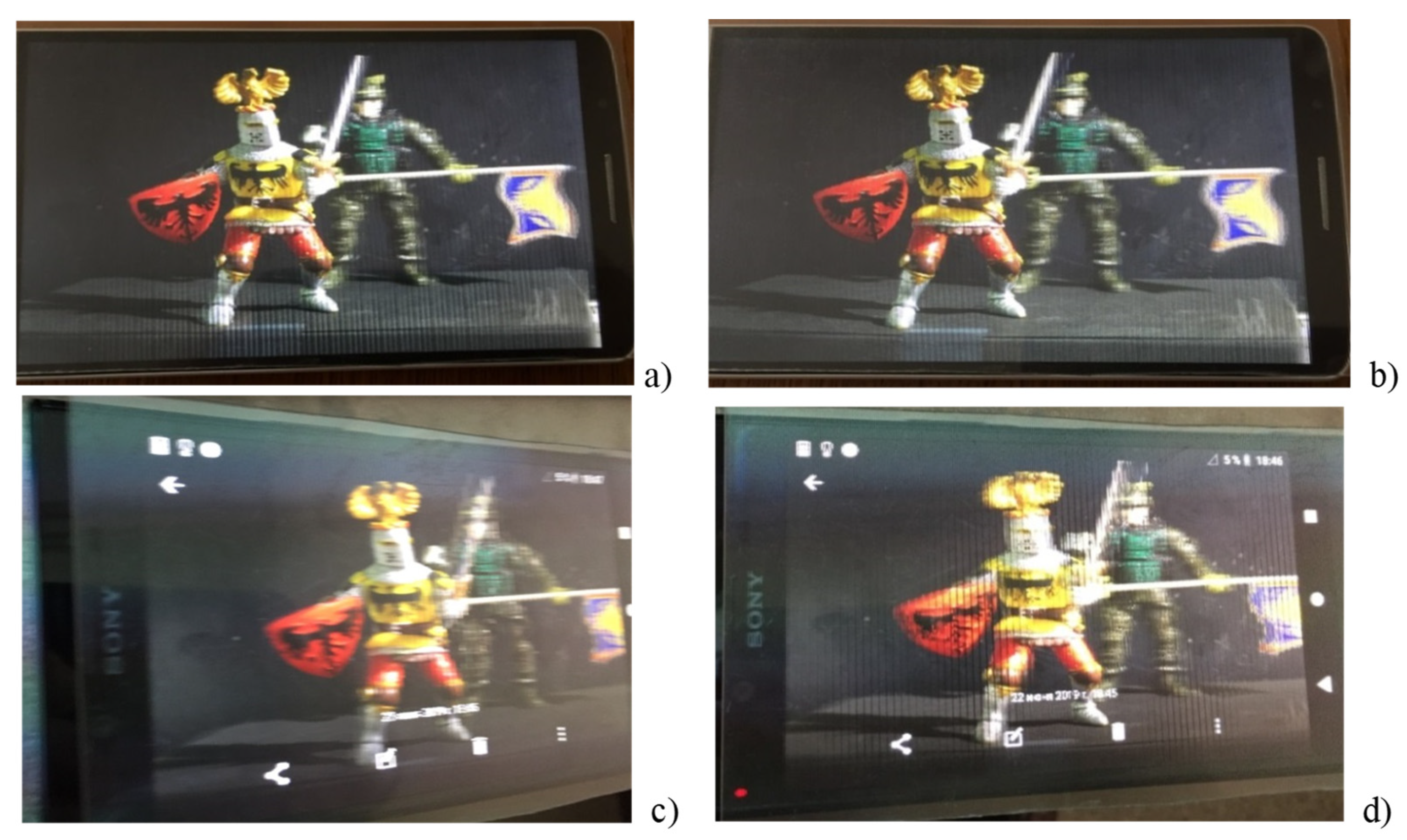
4. Mobile 3D Display

The design of the system consisting of a mobile phone screen and a lenticular lens is shown in Figure 10. Light rays from the mobile phone display element are incident on a lenticular screen, which creates viewing points for observations. The viewing angle can be increased if a lenticular sheet is placed on the surface of a mobile phone, as shown in Figure 10. It can be seen that, unlike a 3D system based on projectors, we do not use a diffuser layer on the screen here. In addition, the lens array is located on the mobile phone screen in such a way that the surfaces of the elementary lenses directly touch the phone screen. This allows us to increase the viewing angle and image depth.
Mobile 3D display consists of a commercial mobile phone 2D display and a lenticular lens array. We used smartphones with different pixel structures (Figure 11): 4K Sony (resolution 3840 × 2160) and Samsung and LG (resolution 2560 × 1440). Specifications are presented in Table 2.

Experimental Results

Below, the images using mobile phones 4K Sony and LG with IPS LCD displays are presented. Lenticular sheets with 40 LPI and 70 LPI of different thicknesses were used in the experiments (Figure 12).
An important step is a pitch test. The need for the pitch test is to avoid misalignment between the lenticular sheet and the image that is prepared for displaying.
Below, 3D images obtained using mobile devices are presented. A system consisting of a mobile phone with IPS LCD display matrix and a lenticular lens sheet with 70 LPI (lens pitch is 363 μm) has been developed. Note that a 3D display system using a mobile phone with a diamond pentile OLED display panel has been demonstrated in [23]. In [24] the 3D display consisting of a 2D OLED display panel, a pixel mask, and a lenticular lens was proposed.
In Figure 13 and Figure 14 the images from different viewing directions are shown. Here we used LG G3 mobile phone (resolution 2560 × 1440 pixels). Three-dimensional images with eight views were created. Three-dimensional image has the ability to “look around”. It is seen that the LED source, which is hidden for viewing in the image on the right, become visible from a different angle of view (left image).
In Figure 15, the images using an LG G3 (2560 × 1440 pixels) mobile phone and a 4K Sony Xperia XZ Premium (3840 × 2160 pixels) mobile phone and lenticular lens with 70 LPI are presented. Three-dimensional images with eight and twelve views were created.
Although the resolution of 4K Sony mobile phone is higher than LG G3 phone, the picture quality is better when using the LG phone. This is because the number of views under each lenticular lens for the LG phone (N = lens pitch/pixel size = 7.9) is closer to an integer value than for the 4K Sony phone (N = 12.5).

5. Discussion

Thus, the possibility of design of 3D image systems using low-cost devices and materials is demonstrated. Lenticular lens arrays were used in the experiments to control the light rays. Diffraction gratings and microstructures can also be used to control the direction of propagation of light rays in 3D displays [25,26,27]. Recently, a diffraction-grating-based 3D display was designed using a multi-view concept [28]. In [29], an optimum design is proposed for diffraction-grating 3D displays. It is known that rainbow holograms are based on first-order diffraction gratings which may generate 3D colored images in reflection [30]. In [31], the novel type of diffraction gratings with periods supporting first-order diffraction in the visible wavelength range was proposed. These gratings show coloring of the transmitted zeroth order due to excitation of surface plasmons. Two-dimensional free-form lens arrays and holographic diffusers can also be used to increase the view angle, depth range, and resolution [32,33].
Crosstalk (ghosting) is the main problem of perception in the 3D display system [34,35,36]. Crosstalk usually occurs at large viewing angles. Crosstalk can be reduced by optimizing the view distribution in the 3D image file [24]. In [37], an accurate 3D autostereoscopic display method using optimized parameters by quantitative calibration is proposed. Crosstalk can also be eliminated if a lens array with aspherical surfaces is used [38]. Low crosstalk was obtained in [39] using dynamically tuned directional backlight. Future developments are considered in the creation of 3D display architecture based on the use of orbital angular momentum (OAM)-carrying light beams [40,41]. This could lead to the next generation of multi-view 3D display technologies. It is shown in [35] that in the choice of encoding/decoding modes, Laguerre–Gauss (LG) modes will allow the reduction of crosstalk in the restored images. Note that the LG modes are the solutions of the Maxwell equations in graded-index optical fibers [42,43]. This compatibility between OAM-based 3D display and data communication using optical fiber may provide the possibility for all-optical collection, transmission, and rendering of 3D information.
A new method of visualization of 3D objects is the correlation method of obtaining images (ghost imaging) [44]. The ghost image uses optical correlations, i.e., even if the information from any of the detectors used to create the image does not create an image, the image can be obtained using optical correlations. This visualization process does not use optical lenses, and the image itself does not contain distortion.
The concept of a three-dimensional image in the time domain is also of practical interest. Usually in temporal optics, signals are treated similarly to objects in spatial optics and temporal visualization is based on the analogy of two-dimensional spatial image schemes [45].
One of the important tasks is to transfer 3D images to remote distances from the focusing system or to obtain images from hard-to-reach areas. Traditional methods do not allow images to be obtained at large distances from the imaging optical system. We have previously discovered the effect of periodic revival of the spatial distribution of the intensity of the wave packet at large distances during non-paraxial propagation in a graded-index optical fiber due to interference between the waveguide modes [43,46]. It has been shown that a strongly focused beam of light can be efficiently transmitted over a long distance in optical fiber with a revival period. This demonstrates the possibility of transmitting an image over an optical waveguide over long distances from the object.

6. Conclusions

Thus, the possibility of performing optical design of 3D display systems based on projectors and mobile devices is demonstrated. It is shown that a simple algorithm can be applied to create 3D image files when a rotating platform is used to capture images. Using projectors has a number of advantages, including accurate alignment of the screen with the image pixels. Three-dimensional images with smooth motion parallax are demonstrated at a viewing angle of 35 degrees. The image depth corresponds to the actual depth of the captured 3D scene. The ability to “look around” the object is experimentally shown. The use of Ultra HD 4K projectors allowed us to demonstrate 4K 3D images without having to solve the problems of boundary and color. A new design of the display screen for mobile phones is proposed, which allowed us to solve the problem of aligning the display pixels with the lens array. For the experimental demonstration of high-resolution 3D images, the optimal lens array and the type of display matrix were selected. This allowed us to increase the viewing angle and image depth. It is shown that if it is necessary to use a diffuser layer in the case of projectors, then such a layer is not needed for mobile phones. The proposed displays have a wide range of potential applications, including 3D TVs and projection systems, mobile phones, technologies for applications in the field of information transmission, processing, and storage, as well as systems for use in video conferencing and in medicine.

Author Contributions

Conceptualization, N.P.; design of the experiments, N.P., M.K. and Y.S.; image capturing, Y.S.; creation of 3D image files, M.K. and Y.S.; performing the experiments, M.K. and Y.S.; writing the paper, N.P.; supervision, N.P. All authors have read and agreed to the published version of the manuscript.

Funding

This research was funded by the Ministry of Science and Higher Education of the Russian Federation under the State contract No. 0069-2019-0006 and by the Russian Foundation for Basic Research, project number 19-29-11026.

Conflicts of Interest

The authors declare no conflict of interest.

References

  1. Geng, J. Three-dimensional display technologies. Adv. Opt. Photonics 2013, 5, 456–535. [Google Scholar] [CrossRef] [Green Version]
  2. Hong, J.; Kim, Y.; Choi, H.J.; Hahn, J.; Park, J.H.; Kim, H.; Min, S.W.; Chen, N.; Lee, B. Three-dimensional display technologies of recent interest: Principles, status, and issues. Appl. Opt. 2011, 50, 87–115. [Google Scholar] [CrossRef] [Green Version]
  3. Lueder, E. 3D Displays; John Wiley & Sons: Chichester, UK, 2012. [Google Scholar]
  4. Javidi, B.; Carnicer, A.; Arai, J.; Fudjii, T.; Hua, H.; Liao, H.; Martínez-Corral, M.; Pla, F.; Stern, A.; Waller, L.; et al. Roadmap on 3D integral imaging: Sensing, processing, and display. Opt. Express 2020, 28, 32266–32293. [Google Scholar] [CrossRef] [PubMed]
  5. Jang, J.S.; Javidi, B. Real-time all-optical three-dimensional integral imaging projector. Appl. Opt. 2002, 41, 4866–4869. [Google Scholar] [CrossRef] [PubMed]
  6. Liao, H.; Iwahara, M.; Hata, N.; Dohi, T. High-quality integral videography using a multiprojector. Opt. Express 2004, 12, 1067–1076. [Google Scholar] [CrossRef]
  7. Jang, J.S.; Javidi, B. Three-dimensional projection integral imaging using micro-convex-mirror arrays. Opt. Express 2004, 12, 1077–1083. [Google Scholar] [CrossRef]
  8. Kim, Y.; Park, S.G.; Min, S.W.; Lee, B. Projection-type integral imaging system using multiple elemental image layers. Appl. Opt. 2011, 50, B18–B24. [Google Scholar] [CrossRef] [PubMed]
  9. Jang, J.Y.; Shin, D.; Lee, B.G.; Kim, E.S. Multi-projection integral imaging by use of a convex mirror array. Opt. Lett. 2014, 39, 2853–2856. [Google Scholar] [CrossRef]
  10. Takaki, Y.; Nago, N. Multi-projection of lenticular displays to construct a 256-view super multi-view display. Opt. Express 2010, 18, 8824–8835. [Google Scholar] [CrossRef]
  11. Takaki, Y.; Takenaka, H.; Morimoto, Y.; Konuma, O.; Hirabayashi, K. Multi-view display module employing MEMS projector array. Opt. Express 2012, 20, 28257–28266. [Google Scholar] [CrossRef]
  12. Lee, J.H.; Park, J.; Nam, D.; Choi, S.Y.; Park, D.S.; Kim, C.Y. Optimal projector configuration design for 300-Mpixel multi-projection 3D display. Opt. Express 2013, 21, 26820–26835. [Google Scholar] [CrossRef]
  13. Wang, Z.; Wang, A.; Wang, S.; Ma, X.; Ming, H. Resolution-enhanced integral imaging using two micro-lens arrays with different focal lengths for capturing and display. Opt. Express 2015, 23, 28970–28977. [Google Scholar] [CrossRef] [Green Version]
  14. Petrov, N.I.; Khromov, M.N.; Nikitin, V.G.; Sokolov, Y.M. 3D imaging systems based on projectors and mobile phones. In Proceedings of the SPIE Digital Optical Technologies, Munich, Germany, 24–27 June 2019; Volume 11062, p. 110620N. [Google Scholar]
  15. Petrov, N.I.; Khromov, M.N.; Sokolov, Y.M. Large-screen multi-view 3D display. OSA Contin. 2019, 2, 2601–2613. [Google Scholar] [CrossRef]
  16. Okaichi, N.; Miura, M.; Sasaki, H.; Watanabe, H.; Arai, J.; Kawakita, M.; Mishina, T. Continuous combination of viewing zones in integral three-dimensional display using multiple projectors. Opt. Eng. 2018, 57, 061611. [Google Scholar]
  17. Kim, J.; Lee, C.K.; Jeong, Y.; Jang, C.; Hong, J.Y.; Lee, W.; Shin, Y.C.; Yoon, J.H.; Lee, B. Crosstalk-reduced dual-mode mobile 3D display. J. Disp. Technol. 2015, 11, 97–103. [Google Scholar] [CrossRef]
  18. Markman, A.; Wang, J.; Javidi, B. Three-dimensional integral imaging displays using a quick-response encoded elemental image array. Optica 2014, 1, 332–335. [Google Scholar] [CrossRef]
  19. Jung, S.M.; Kang, I.B. Three-dimensional modeling of light rays on the surface of a slanted lenticular array for autostereoscopic displays. Appl. Opt. 2013, 52, 5591–5599. [Google Scholar] [CrossRef]
  20. Kim, H.; Hahn, J.; Choi, H.J. Numerical investigation on the viewing angle of a lenticular three-dimensional display with a triplet lens array. Appl. Opt. 2011, 50, 1534–1540. [Google Scholar] [CrossRef]
  21. Jang, J.; Hong, J.; Kim, H.; Hahn, J. Light-folded projection three-dimensional display. Appl. Opt. 2013, 52, 2162–2168. [Google Scholar] [CrossRef] [PubMed] [Green Version]
  22. Petrov, N.I.; Petrova, G.N. Diffraction of partially-coherent light beams by microlens arrays. Opt. Express 2017, 25, 22545–22564. [Google Scholar] [CrossRef]
  23. Algorri, J.F.; Pozo, V.U.; Sanchez-Pena, J.M.; Oton, J.M. An autostereoscopic device for mobile applications based on a liquid crystal microlens array and an OLED display. J. Disp. Technol. 2014, 10, 713–720. [Google Scholar] [CrossRef] [Green Version]
  24. Lv, G.J.; Zhao, B.C.; Wu, F.; Wang, Q.H. Three-dimensional display with optimized view distribution. Opt. Eng. 2019, 58, 023108. [Google Scholar] [CrossRef]
  25. Kulick, J.H.; Nordin, G.P.; Parker, A.; Kowel, S.T.; Lindquist, R.G.; Jones, M.; Nasiatka, P. Partial pixels: A three-dimensional diffractive display architecture. J. Opt. Soc. Am. A 1995, 12, 73–83. [Google Scholar] [CrossRef]
  26. Petrov, N.I. Splitting the bandwidth of a frustrated total internal reflection filter with nanoparticle inclusions. OSA Contin. 2020, 3, 2591–2601. [Google Scholar] [CrossRef]
  27. Petrov, N.I.; Danilov, V.A.; Popov, V.V.; Usievich, B.A. Large positive and negative Goos-Hänchen shifts near the surface plasmon resonance in subwavelength grating. Opt. Express 2020, 28, 7552–7564. [Google Scholar] [CrossRef]
  28. Fattal, D.; Peng, Z.; Tran, T.; Vo, S.; Fiorentino, M.; Brug, J.; Beausoleil, R.G. A multi-directional backlight for a wide-angle, glasses free three-dimensional display. Nature 2013, 495, 348–351. [Google Scholar] [CrossRef]
  29. Jeong, Y.J. Diffraction grating 3D display optimization. Appl. Opt. 2019, 58, A21–A25. [Google Scholar] [CrossRef] [PubMed]
  30. Denisyuk, Y.N. Three-dimensional and pseudodeep holograms. J. Opt. Soc. Am. A 1992, 9, 1141–1147. [Google Scholar] [CrossRef]
  31. Lochbihler, H.; Kleemann, B.H. Semi-permeable resonant aluminum gratings for structural coloration in transmission. Opt. Lett. 2021, 48, 2200–2203. [Google Scholar] [CrossRef]
  32. Petrov, N.I. Design of free-form surface backlight unit for displays. In Proceedings of the SPIE Digital Optical Technologies, Munich, Germany, 24–27 June 2019; Volume 11062, p. 1106206. [Google Scholar]
  33. Petrov, N.I. Holographic diffuser with controlled scattering indicatrix. Comput. Opt. 2017, 41, 831–836. [Google Scholar] [CrossRef] [Green Version]
  34. Woods, A.J. Crosstalk in stereoscopic displays: A review. J. Electron. Imaging 2012, 21, 040902. [Google Scholar] [CrossRef]
  35. Woods, A.J.; Harris, C.R.; Leggo, D.B.; Rourke, T.M. Characterizing and reducing crosstalk in printed anaglyph stereoscopic 3D images. Opt. Eng. 2013, 52, 043203. [Google Scholar] [CrossRef] [Green Version]
  36. Son, J.Y.; Lee, B.R.; Park, M.C.; Leportier, T. Crosstalk in multiview 3-D images. In Proceedings of the SPIE Sensing Technology + Applications, Baltimore, MD, USA, 20–24 April 2015; Volume 9495, p. 94950P. [Google Scholar]
  37. Fan, Z.; Chen, G.; Xia, Y.; Huang, T.; Liao, H. Accurate 3D autostereoscopic display using optimized parameters through quantitative calibration. J. Opt. Soc. Am. A 2017, 34, 804–812. [Google Scholar] [CrossRef]
  38. Yang, S.; Sang, X.; Xu, X.; Gao, X.; Liu, L.; Liu, B.; Yang, L. 162-inch 3D light field display based on aspheric lens array and holographic functional screen. Opt. Express 2018, 26, 33013–33021. [Google Scholar] [CrossRef]
  39. Li, X.; Ding, J.; Zhang, H.; Chen, M.; Liang, W.; Wang, S.; Fan, H.; Li, K.; Zhou, J. Adaptive glasses-free 3D display with extended continuous viewing volume by dynamically configured directional backlight. OSA Contin. 2020, 3, 1555–1567. [Google Scholar] [CrossRef]
  40. Li, X.; Chu, J.; Smithwick, Q.; Chu, D. Automultiscopic displays based on orbital angular momentum of light. J. Opt. 2016, 18, 085608. [Google Scholar] [CrossRef] [Green Version]
  41. Chu, J.; Chu, D.; Smithwick, Q. Off-axis points encoding/decoding with orbital angular momentum spectrum. Sci. Rep. 2017, 7, 43757. [Google Scholar] [CrossRef] [Green Version]
  42. Petrov, N.I. Vector Laguerre–Gauss beams with polarization-orbital angular momentum entanglement in a graded-index medium. J. Opt. Soc. Am. A 2016, 33, 1363–1369. [Google Scholar] [CrossRef] [PubMed] [Green Version]
  43. Petrov, N.I. Depolarization of light in optical fibers: Effects of diffraction and spin-orbit interaction. Fibers 2021, 9, 34. [Google Scholar] [CrossRef]
  44. Liu, J.T.; Li, J.; Huang, J.B.; Cai, X.M.; Deng, X.; Zhang, D.J. Single-pixel ghost imaging based on mobile phones. Opt. Eng. 2019, 58, 023106. [Google Scholar] [CrossRef]
  45. Klein, A.; Yaron, T.; Preter, E.; Duadi, H.; Fridman, M. Temporal depth imaging. Optica 2017, 4, 502–506. [Google Scholar] [CrossRef]
  46. Petrov, N.I. Macroscopic quantum effects for classical light. Phys. Rev. A 2014, 90, 043814. [Google Scholar] [CrossRef] [Green Version]
Figure 1. Schematic view of projector-based 3D display system: 1—projector; 2—display element; 3—projection lens; 4—elemental image; 5—diffuser layer; 6—lenticular lens; 7—viewing zone; 8—observer. The shaded areas show different areas of vision. Adapted from [15].
Photonics 08 00331 g001
Figure 2. Two-dimensional image capturing by a camera.
Photonics 08 00331 g002
Figure 3. Schematic representation of 3D image file creation method. Adapted from [15].
Photonics 08 00331 g003
Figure 4. Flowchart of the 3D image files creation method.
Photonics 08 00331 g004
Figure 5. (a) Example of 3D image file created in MatLab; (b) 3D image with lens array.
Photonics 08 00331 g005aPhotonics 08 00331 g005b
Figure 6. (a) Rear view of multi-projector 3D imaging system; (b) 4K projector in the front and four full HD projectors in the background.
Photonics 08 00331 g006
Figure 7. Images at different viewing directions. (a) The face of the green warrior is not covered by the sword; (b) the face of the warrior is covered by the sword. Displacements of different parts of fighters are shown by arrows.
Photonics 08 00331 g007
Figure 8. Images at different viewing angles: red LED is seen in the picture (a); LED light is covered with a foot of the warrior (b).
Photonics 08 00331 g008
Figure 9. Forty inch 3D images using 4K ultra HD projector. (a) View from the left; (b) view from the right.
Photonics 08 00331 g009aPhotonics 08 00331 g009b
Figure 10. Schematic view of the mobile 3D display. 1—Display element; 2—glass plate; 3—lenticular lens; 4—viewing zone; 5—observer; φ—viewing angle; D—lens-pitch; f—focal length; and R—curvature radius of the elemental lens.
Photonics 08 00331 g010
Figure 11. Images of pixel structures: (a) LG G3—IPS; (b) 4K Sony Xperia—IPS; (c) Samsung Galaxy Note 4—diamond pixel structure; (d) Samsung Galaxy S7—diamond pixel structure. Numbers from 1 to 6 correspond to the view numbers.
Photonics 08 00331 g011
Figure 12. Three-dimensional image files with 40 LPI (left) and 70 LPI (right) lenticular screens.
Photonics 08 00331 g012
Figure 13. Images on the mobile phone screen from different viewing angles. (a) view from the center; (b) view from the right.
Photonics 08 00331 g013
Figure 14. Three-dimensional images on the screen from different viewing directions. Relative displacements of different parts of fighters are shown by the arrows.
Photonics 08 00331 g014
Figure 15. Three-dimensional images on the LG G3 (a,b) and 4K Sony (c,d) mobile phones from different viewing directions.
Photonics 08 00331 g015
Table 1. Parameters of the lenticular array and projector.
Lenticular ArrayPitch1.27 mm (20 lpi)
Focal length
Thickness
2.04 mm
3.25 mm
ProjectorResolution1920 × 1080
3840 × 2160
3D imageResolution
Viewing angle
1920 × 1080
3840 × 2160
35
Table 2. Characteristics of mobile phones.
Mobile DeviceDisplay Screen Size, inDisplay Resolution,
Pixel Size
Display Matrix Type
LG G35.522560 × 1440
534 ppi
46 μm
IPS LCD
4K Sony Xperia XZ 3840 × 2160
5.46807 ppi
29 μm
IPS LCD
Samsung Galaxy Note 4 2560 × 1440
5.7515 ppiOLED Diamond
49 μm
Samsung Galaxy S7 2560 × 1440
5.1577 ppi
44 μm
OLED Diamond
Publisher’s Note: MDPI stays neutral with regard to jurisdictional claims in published maps and institutional affiliations.

