1. Introduction
In optical packet switching (OPS) [
1,
2,
3], contention resolution has great importance for packet processing in storage, switching, synchronization, and congestion management. Packet buffering is a fundamental approach for dealing with contentions. Implementing a buffer in the network node reduces the probability of congestions resulting from the simultaneously received packets directed to the same output port. All-optical buffering has low processing delay and power consumption. The avoidance of switching signals between the optical and electrical domains in all-optical buffering achieves a released limitation on the signal bandwidth. However, the challenges regarding the buffer scalability and flexibility in such systems are still not adequately addressed, although several impressive results have been presented in [
4,
5,
6].
Electrical technologies are included in optical packet queuing to support relatively large capacity and random access. Some representative examples can be found in [
7,
8,
9], where a forwarding node based on the switching fabric structure provides the received signals with two possible operations. One action is to send the packets directly through the switch, while the other is to address the packets to the buffering block. The node architecture executes the packets in the optical domain to reduce optical-electronic-optical (OEO) conversions and the processing latency when the traffic intensity is low. If the traffic volume is so high that the pure optical switching cannot be supported for all arrivals, packet buffering, including optical and electrical signal processing, is activated.
In the scenarios mentioned above, the packets propagating in a single fiber are carried by a single carrier or different wavelengths. Only a single-wavelength or a wavelength-division multiplexing (WDM) system is considered. Recent advances in all-optical codecs provide an incentive to queue packets via optical code processing. Code-switching models, which possess similar characteristics in block probabilities of the general buffering schemes [
10,
11,
12], have been implemented in OPS for contention resolution. Using optical codes in buffering adopts the concept of an optical multiplexing technique known as optical code-division multiple access (OCDMA), where multiple data streams are modulated onto different coded carriers. The system capacity of OCDMA is increased as the coded signals are allowed to be transmitted simultaneously in a single channel with some error probabilities. In optical code-based buffering, a light code is denoted as a packet label, and the buffering process includes inscribing and extracting a header into and from an optical packet. Note that the label processing can be executed in the time, wavelength domain, or the combination of both. However, the existing scenarios used the existing code-words. As the code properties dominate OCDMA performance [
13], it is expected to improve the buffering efficiency through modifying the code structure.
In this paper, an optical buffering solution based on label switching of pseudo-orthogonal codes is proposed. The buffer overflow occurs when label switching fails to perform on the buffered packets due to the insufficient labels. Assigning an increased code number to the buffer could reduce the overflow effect, but the efficiency of this solution is mitigated by the decoder noise. Therefore, we study a noise-immune labeling method of residual function by advancing the correlation properties of the existing codes. Compared with the input code-words, the residual function output has a slightly shorter code length and a lower average cross-correlation value. Previous studies have shown compelling evidence that employing low-cross-correlation codes results in a low photocurrent variance at the photo-detector output [
14,
15]. Therefore, the label-switching buffer based on the proposed codes is more resilient to decoder noises. The buffering efficiency is evaluated in terms of code-error probability, which considers two physical-layer indices of packet blocking probability and label-error rate. The proposed label-switching scheme improves the solution efficiency to buffer overflow as a lower code-error probability can be reached.
Another contribution of this paper is that we extend the optical and electrical combined structure in a forwarding node [
7,
8,
9] to generate and process the residual-coded labels of spectral amplitude coding (SAC) [
16,
17,
18]. A SAC signal is expressed by a set of optical wavelengths, which commonly come from filtering and slicing the light source spectrum by fiber Bragg gratings (FBGs). We have demonstrated that the codec structure of the residual coded labels has a saved component number and an increased efficiency in power utilization.
2. Materials and Methods
This section introduces the execution of residual function [
19] on the code processing for generating the desired labels for packet buffering. A family of stuffed quadratic congruence (SQC) codes [
16] is taken as the function input in the following exemplar demonstration. These codes have the correlation properties of (
N,
ω,
λ) = (
p2 +
p + 1,
p + 1, 1), where
N is the code length,
ω is the code weight,
λ is the in-phase cross-correlation, and
p is a positive prime number. The steps of constructing a family of residual SQC (RSQC) codes are listed as follows. First, define a matrix
S(N−1)×N that includes
N − 1 row vectors, with each of them corresponding to a distinctive SQC code-word. Second, select one of the row vectors
si = [
si(1),
si(2), …,
si(
N)] in
S and delete the matrix columns corresponding to the positions of chips “1” in
si (
si(
j) = 1), where 1 ≤
i,
j ≤
N. After step 2 is performed, the matrix size shrinks from (
N − 1) ×
N to (
N − 1) × (
N − p − 1). Finally, remove the selected row vector
si from the matrix of step 2. The processed code matrix is denoted as
R(N−1)×(N−p−1), which includes
N − 1 row vectors of RSQC code-words of code weight
p and code length
p2.
Table 1 shows the RSQC matrix derived from processing the SQC codes of (13, 4, 1) and
p = 3. The central part of this table is a list of 12 SQC codes with the length of 13. Each SQC vector is denoted as
si shown in the right-most column, where 1 ≤
i ≤ 12. The two parameters,
m and
n, in the left two columns are the indices of the RSQC code vectors
rmn, where 1 ≤
m ≤ 4 and 1 ≤
n ≤ 3. In this example,
s1 = (100 001 100 0100) is selected as the deleted code-word. As chips “1” are at the 1st, 6th, 7th, and 11th positions in
s1, the corresponding four columns are deleted from the original matrix
S12×13. After removing
s1, a matrix of RSQC codes with weight 4 and length 9 is constructed. In this table, the permutation of row vectors is based on the cross-correlations values between code-words. Any two codes with an identical index
m have the
λ of 0, while the two with different indices
m have 1. The deleted rows and columns are marked with single-line strikethrough, and the generated RSQC codes are marked in red. Based on the above discussion, the correlation equation of RSQC codes is deducted as follows:
The final row vector is not a conventional SQC code-word, but it still fits the corresponding correlation properties. Therefore, it can be treated as an extra RSQC code-word after the code processing. Based on
Table 1, despite a shorter code length for a given
p, RSQC codes have the same code cardinality or the available code number as SQC.
Figure 1 shows the three-dimension bar charts of the code correlations of RSQC and SQC for
p = 3. The former values can be derived from substituting the code parameter of RSQC (
p = 3) into (1), while the latter ones come from substituting
p = 3 into the correlation properties of SQC codes (
ω =
p + 1,
λ = 1). We simplify the denotation of RSQC code
rmn as
ri, where
i = (
m − 1)
p +
n. The heights of the diagonal bars represent the autocorrelation values, while the non-diagonal ones represent the cross-correlations. One can find the RSQC’s cross-correlations are less than or equal to SQC’s. Previous results have shown that codes with a low
λ are superior in suppressing the decoder noise in the coding schemes of SAC [
18,
19,
20]. Therefore, an increased signal-to-noise ratio (SNR) of the decoded signals is expected when RSQC codes are used as the packet labels for buffering.
In core routers in the optical packet-switched network (OPS), the received packets can be directly switched to the desired paths if no competitions for the same path occur. If multiple packets are simultaneously sent to a router output without processing, the collisions make packets missing. In the proposed buffering scheme, the buffered packets are marked with different label codes. The collisions can be avoided by using the detection scheme based on the correlation properties of the label codes. An individual packet can be identified from the multiplexed signals without interferences. To perform the above buffering function, routers must implement decoders to read the packets’ label information. If the packets having the same destination carry an identical label, they are switched to different encoders for label renewing. Therefore, label identification, switching, and label generation are required to be implemented in the router structure to support the buffering service.
The node architecture that supports buffering the residual-coded packets is shown in
Figure 2. There are
F input fibers and a single output fiber in this exemplar diagram, while the architecture is scalable to arbitrary numbers of outputs. Each fiber can carry at most
C packets simultaneously, where
C is the code cardinality or the code number for a given length. The received packets are primarily proceeded to obtain their destination information. The node architecture includes switching and buffering blocks, respectively depicted in the upper and lower node structures. If the simultaneously received packets do not have a common destination port, packet congestion will not occur so that the buffering service is not required. As there are no blocking connections, simply the switching service is sufficient for guiding the packets to the desired outputs. Those packets directly leave the node from the upper
F output ports of the
F × 2
F optical cross-connect (OXC).
Packets having the same destination cannot be directly switched as collisions will occur at the destined output port. Therefore, after port determination, they are set to the buffering block based on label switching from the lower F paths of the OXC. Each received signal at one of F buffer’s inputs is broadcast to C decoders to retrieve their label information and determine the code occupancies. The carried labels must be kept different to avoid confusion when packets are routed to the buffer output. Therefore, for the packets having an identical label, their labels are firstly removed by the decoders. Then the electrical switch sets up connections to route the decoded electrical payloads to the unused encoders for label renewing. Note that the electrical switch would not set up any connections if the unoccupied codes are unavailable. In this case, the packet is seen as blocked as it does not go through a complete label-switching process.
To conclude the buffer’s characteristics, it has a fixed size of K, where K is the encoder number. Although deploying more encoders enlarges the buffer size, the increased cost and component number should be considered. Another notable characteristic is that in such buffer at most K queued packets can be multiplexed in a shared time duration of T, where T is the packet length, assuming that all packets are synchronized and have the same length. The reason is that interference-free decoding can be realized by employing the balanced detection scheme based on the labels’ pseudo-orthogonal property. If several packets are competing for a common output port, they can be forwarded to the destination simultaneously without spreading them over different periods. It is allowable that the packets overlap in the time domain without worrying about the collisions or interferences because they are respectively marked with different label codes. On the other hand, the existing fiber delay line (FDL) buffers suffer from less time efficiency as at least KT time resources are required for storing all packets.
Considering the detailed codec structure in the buffering block, we design two encoders for generating SAC signals of RSQC and SQC codes. SAC is a widespread coding scheme of OCDMA systems due to its low cost and system complexity. The presences and absences of wavelengths in SAC represent the chips “1” and “0” in a code sequence, respectively. The major components in SAC encoders are FBGs, which are employed to filter out the desired wavelengths from a light source’s spectrum.
Figure 3a shows the FBG-based encoder array of three RSQC codes,
r11,
r12, and
r13, with
N = 9. The first FBG group reflects three wavelengths, λ
4, λ
5, and λ
7, to generate the corresponding SAC label of
r11 = (000110100). As the three labels do not have any common wavelengths, the remaining components can still be employed to generate the next coded label after removing the ones mapping the previous code-word. Therefore, a single light source is sufficient for performing the optical encoding of a group of RSQC codes having zero cross-correlation. On the other hand, generating another RSQC group requires an extra encoder, as two labels belonging to different groups cannot share a common source due to the overlapping wavelengths.
Figure 3b shows the encoder array of three SQC codes with
N = 13. Based on the correlation properties of SQC codes, any two labels have a common position of chip “1”. Therefore, multiple SQC signals in SAC must be generated from distinct sources to avoid two signals contending for a common wavelength. Due to the extra power requirement, the SQC system suffers a lower power efficiency than the RSQC one. Moreover, efficient utilization in bandwidth is achieved in RSQC as well, as a given number of labeled packets can be multiplexed with a reduced number of wavelengths.
In an FBG encoder, the wavelength components of a given label code have slightly different time delays. Taking r11 as an example, according to the grating permutation in the array, λ5 travels a longer distance than λ4 before the second FBG bounces it back. Similarly, compared with the two wavelengths mentioned earlier, λ7 has the greatest delay. The time difference between chips can be compensated by connecting an extra FBG group with precisely the same grating components that placed in a reverse order. In this way, the time-synchronization among chips is achieved as different wavelengths can be simultaneously incorporated into a coded pulse.
3. Results
This section analyzes the buffering performance based on the proposed label switching of residual codes. Previous studies have shown that the packet traffic for a code-switching model can be well approximated by a queuing system [
10]. Therefore, we derive the performance measures by characterizing the proposed buffer structure as the Erlang model. Note that only the packets receiving the buffering service are considered. The buffer, label-switching process, and packet entry are seen as the service center, provided service, and customers, respectively. In the buffering process based on label switching, a queued packet’s previous label code is replaced by a new one when leaving from the buffer output. Label renewing is performed whenever an available encoder is found, and multiple encoders are allowed to work simultaneously. An individual encoder is effectively treated as a unit-capacity server because only up to one code can be generated in a given time frame.
We have modeled the proposed buffering block consisting of
K encoders as an M/M/
K/
K system based on the above features. A single-input structure is considered (
F = 1) in the following analysis, while the method can be scaled to the buffer structures with arbitrary inputs. The M/M/
K/
K system is better suited to approximate the proposed buffering block since the buffer space is finite. The arrival rates of packets entering the decoder array are assumed to be the random variables following a Poisson distribution with mean
γ. The service rates, including the reciprocals of the packet processing times of decoding, switching, and encoding, are assumed to be the random variables following an exponential distribution with mean
μ. This assumption fits the common property of a Markov system with the birth/death process, where at any time point, a packet stays in a state either being the arrival or the completion of buffering. Moreover, the definition of a Markov chain well models the realistic incoming and ongoing traffics of the buffering block. The steady-state probability of exact
i packets in the buffer
P(
i) is given as [
21].
where 0 ≤
i ≤
K and
P(0) denotes the probability of the buffer state being empty, which is expressed as
In (2), P(K) is defined as the packet-blocking probability. In a label-switching buffer based on optical codes, at least one code must be available for label renewing to perform label switching successfully. A packet is blocked if K codes are all distributed, or K packets have already existed in the buffer.
Except for
P(
K), label-error rate (LER) should be considered for performance evaluation. In the proposed scheme, multiple encoders are allowed to simultaneously send the coded packets to a shared output. Although the output signals occupy the same time resource, the balanced detection [
16] can still perform good decoding without multiple-access interference (MAI). Although the proposed code labels merit the similar orthogonal property to the wavelength ones, a code-specific issue known as phase-intensity induced noise (PIIN) dominates the system performance. The non-coherent property of the employed light source raises PIIN when a SAC decoder performs the optical-to-electrical conversion on a labeled packet. As a result, the photocurrent at the decoder output does not correctly reflect the power variations of the received optical signals. This effect is described by the performance measure of LER.
In the following numerical analysis of LER, the buffered packets are treated as bit-synchronizing for simplicity, although this requirement is not essential for executing a successful buffering process. Another assumption is that the light source is un-polarized, and its spectrum is flat over the coded bandwidth. The intensity fluctuation in a practical light source scenario is modeled as the effect of PIIN that causes current variations at the decoder. When the modulation scheme of two-code keying is employed [
12], the decoded photocurrents of the RSQC and SQC-coded packets are respectively given as
where
R is the responsivity of the photodiodes and
Psr is the effective optical power. As for noise sources, PIIN variance can be derived from analyzing the power spectral density (PSD) [
16] of the multiplexed coded signals. When
i buffered packets are simultaneously decoded, the PIIN expression raises at the decoder is expressed as
where ∆
v is the spectrum width of the light source and
B is the noise-equivalent bandwidth of the photo-detector. The symbol of
└┘ denotes the floor function. Both SQC and RSQC variances are increased with
i, but the increment for RSQC is less as it includes several zero-cross-correlation codes which do not contribute to any noise variance. Thermal noise is another main noise factor in SAC decoding with the variance expressed as follows.
where
Sth is the PSD of thermal noise. Finally, the overall LER is expressed as the following formula.
In the above analysis, the power of optical sources is fixed to (p + 1)Psr, and the exact LER(i) values of RSQC and SQC labels can be, respectively, calculated by substituting the code parameters (N, w) = (p2, p) and (p2 + p + 1, p + 1) into (7).
To adequately evaluate the buffering performance based on the proposed label switching of residual codes, a performance measure that considers the combining effect of packet blocking and label error must be investigated. Packet blocking may occur when a packet enters the buffer. If all
K codes have been used, the buffer fails to perform label-switching as the arriving packet’s label cannot be converted to any optical codes. If at least one of the optical codes is available for packet encoding, the packet is not blocked and is successfully buffered. When leaving the buffer, multiple coded packets are multiplexed in the output link. Label error is induced in identifying a specific packet from the multiplexed signals due to the presence of noise sources at decoders. The probability of incorrect decoding is called LER. Overall, in the physical-layer level, a packet is successfully buffered if neither blocked nor incorrectly decoded. Code-error rate is used to quantify the adequate performance by considering both packet-blocking probability and LER effects, which is expressed as
4. Discussion
Figure 4 shows the functions from traffic intensities
ρ to code-error rates for
K = 6 and 8, where
ρ is defined as
γ/
μ. Other function parameters are set to
R = 0.95 W/A,
Psr = −14 dBm, ∆
v = 3.75 THz,
B = 1.25 GHz, and
p = 3. For both labels, code-error rates get higher values when
ρ grows, as an arriving packet has a higher chance of being blocked due to the accelerating packet-filling process. For the RSQC-coded packets, increasing the assigned code number
K results in an improved
Pc(
i) due to the enlarged buffer space. However, this solution is less efficient for the SQC-coded packets due to the significant LER contributing to
Pc(
i). Even if an SQC-coded packet successfully enters the buffer, incorrect decoding still may occur given the low-intensity traffic. This error comes from the large PIIN variance induced by the imperfect correlation properties of SQC codes.
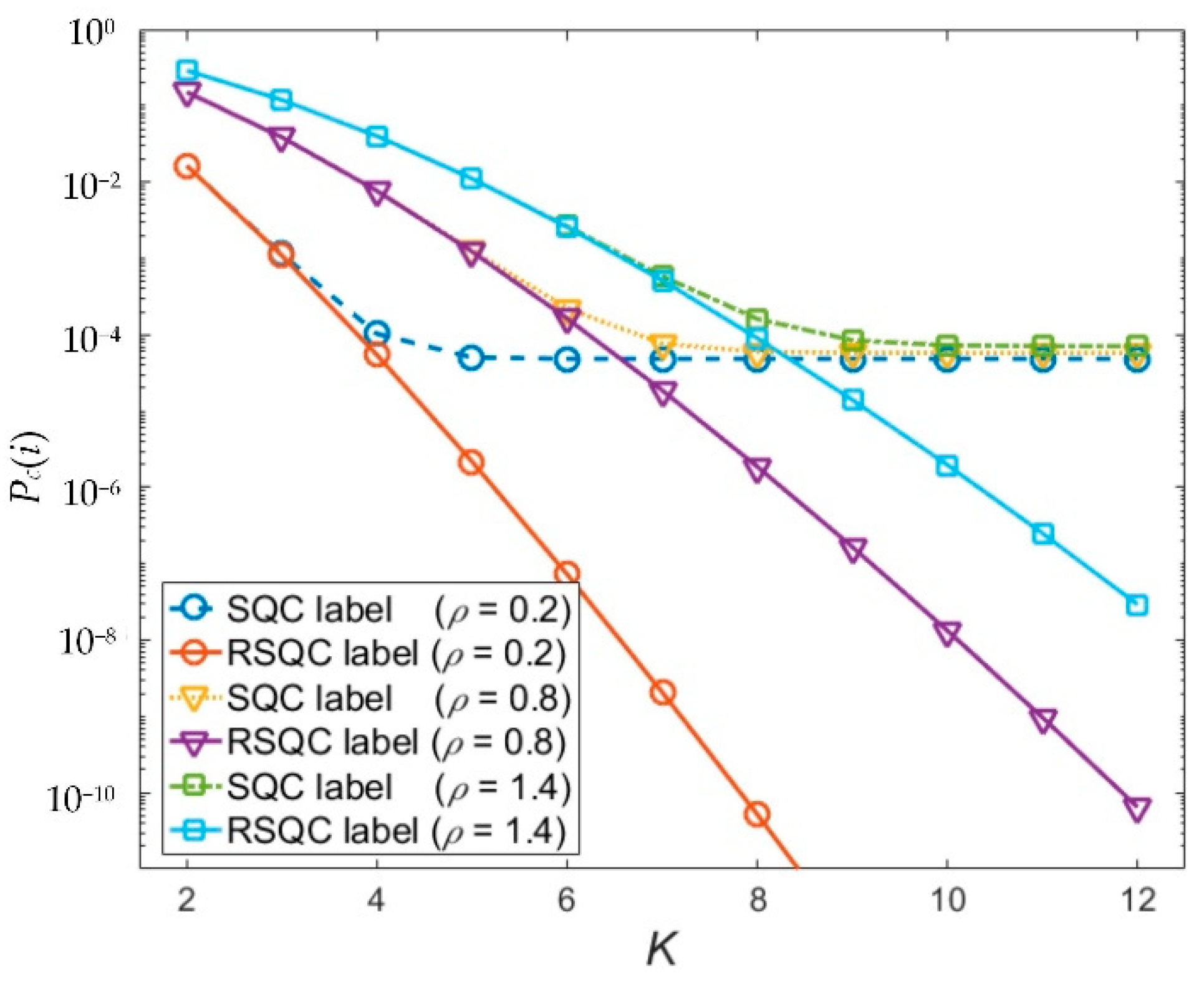
Figure 5 shows the functions that associate the assigned code numbers
K to code-error rates. Both packet-blocking probability and LER are considered in
Pc(
i). The code-error rates of RSQC labels are mainly determined by
P(
K) and
ρ, so merely increasing
K is sufficient for effectively improving the buffering performance. This merit comes from that LER has a relatively negligible effect in
Pc(
i) for RSQC due to its noise-immune characteristic. On the other hand, a large
K does not always indicate a low code-error rate for SQC because LER raising from the increased noise power still remains dominant.
Figure 6 shows the relations between the effective optical power
Psr and
Pc(
i). When
Psr increases, the code-error rates of both labels decrease as a sufficiently large signal power can be measured at the decoder output. Before reaching a common lower bound of
Pc(
i), RSQC labels outperform SQC ones for the following two reasons. First, the input power at the RSQC encoders is larger than the SQC ones for a given source power in the buffer, since the former structure has a lower splitting loss. Second, the noise increment of RSQC labels is less severe when
Psr grows, which results in a higher signal-to-noise ratio (SNR) measured at the decoder. If
Psr is relatively large (>−10 dBm), the noise sources have little to no impact on BER, and the dominant factor becomes
P(
K). In this case,
Pc(
i) performance is irrelevant to
Psr as
P(
K) is primarily determined by
K and
ρ.


