Article

Selective Couplers Based on Multiplexed Volume Holographic Gratings for Waveguide Displays

1
Laser and Optoelectronic Systems Department, Bauman State Technical University, 105005 Moscow, Russia
2
Laser Measurement and Navigation Systems Department, St. Petersburg State Electrotechnical University LETI, 197376 Saint Petersburg, Russia
3
Quantum Electronics Department, Faculty of Physics, St. Petersburg State University, 199034 Saint Petersburg, Russia
*
Author to whom correspondence should be addressed.
Photonics 2021, 8(7), 232; https://doi.org/10.3390/photonics8070232
Submission received: 24 May 2021 / Revised: 17 June 2021 / Accepted: 19 June 2021 / Published: 22 June 2021
(This article belongs to the Special Issue Holography)

Abstract

:
Diffraction waveguides are widely used in augmented reality devices as information display systems for the introduction of data into the human visual field in order to supplement information about the world around us. This paper formulates the principles of radiation conversion in diffraction waveguides made of photo-thermo-refractive glass on the basis of multiplexed volume holographic gratings, and the advantages and disadvantages of high spectral-angular selectivity are analyzed. In the optical scheme, each of the superimposed volume holographic gratings in the diffraction waveguide forms a corresponding part of the composite angular field of view of the augmented reality device. A proposed mathematical model based on angular multiplexing made it possible to synthesize the diffraction optical element for a new type of diffraction waveguide made from photo-thermo-refractive glass and to create a prototype with an angular resolution of at least 3.0 ± 0.5′, with a brightness change in the image of less than 20% and with a composite angular field of view of 32°.

1. Introduction

Augmented reality devices are widely used as information display systems with an aim of introducing into the human visual field any data that complements the information about the world around us. Such devices are necessary for supplying visual instructions during manual operations in medicine, construction and education, as well as in everyday life for expanding smartphone functionality. Diffraction waveguides are commonly used for implementation of augmented reality head-mounted displays [1,2]. Most of these are glass plane-parallel plates where radiation propagates by total internal reflection (TIR), and diffraction gratings are used as couplers to input, redirect and output the light. Diffraction waveguides have low weight (<150 g) and provide an angular field of view at 30–60°, transmittance at 85–90%, and an eyebox of 20–30 mm [3]. Diffraction waveguides can be classified by the diffraction mode of the couplers: based on surface or volume diffraction gratings. Slanted surface gratings [4] are implemented into augmented reality displays by Microsoft HoloLens, Magic Leap, WaveOptics, and Dispelix and they can have a diffraction efficiency up to 80%, but the manufacturing requires a complex and expensive technological process.
Modern mass-produced augmented reality devices based on diffraction waveguides use various photosensitive media (photopolymers, UV-curable polymer compositions, liquid crystal polymer compositions, photoresists, etc.) as materials for phase relief formation, which are sensitive to environmental parameters (humidity, temperature, pressure) and, therefore, must be sealed with cover glass [4,5,6,7]. In particular, volume photosensitive media (for example, silver halide materials and dichromated gelatin) have shrinkage due to their conversion during photochemical processes. Non-optimal operating conditions can lead to a change in the grating parameters and, consequently, to a deterioration in the characteristics and parameters of the image in the augmented reality device. Photo-thermo-refractive (PTR) glass is an alternative to the commonly used photosensitive materials. Its optical properties are equal to the properties of BK7 glass; it has no shrinkage and is not sensitive to temperature changes in the range from −20 °C to +100 °C or ambient humidity [8,9,10]. Thus, volume diffraction optical elements (DOE) made of PTR glass are protected from possible destruction during operation and do not require additional safety glass to ensure safe contact with the waveguide. PTR glass is useful for augmented reality devices because it can serve as a waveguide material as well as a photosensitive media where DOE is formed, thus allowing manufacturers to fully integrate DOE into the waveguide in the implementation.
PTR glass is a volume photosensitive media and is suitable for recording three-dimensional DOEs with high diffraction efficiency and high spectral-angular selectivity. This means that the diffraction gratings formed in the layer (plate) of PTR glass allow us to couple radiation in a narrow spectral band and in a narrow angular field. The application of selective diffraction elements will improve the spectral and angular resolution provided by diffraction waveguides. Therefore, to form a composite field of view above 30° with the help of such selective DOEs, one would need angular multiplexing in order to combine volume holographic gratings (VHG) in one glass region by superimposing the recorded diffraction gratings. Spectral and angular optical couplers based on multiplexed volume holographic gratings (MVHGs) can solve different beam combining and redirection problems: each grating on the DOE transforms its parts of the angular field of view in a certain wavelength band. Modeling the formation of the composite angular field of view according to the selective properties of MVHGs made of PTR glass is the subject of the presented research.

2. Materials and Methods

The mathematical description of a diffraction waveguide containing MVHGs includes two main stages:
  • design of the MVHGs configuration inside the diffraction waveguide, calculation of the geometry by TIR propagation, calculation of the composite field of view and replication of the output pupil;
  • modeling local interaction of electromagnetic light with DOE structure for the prediction of the diffraction efficiency characteristics.
The first stage is based on Bragg’s law and geometric optics, as 
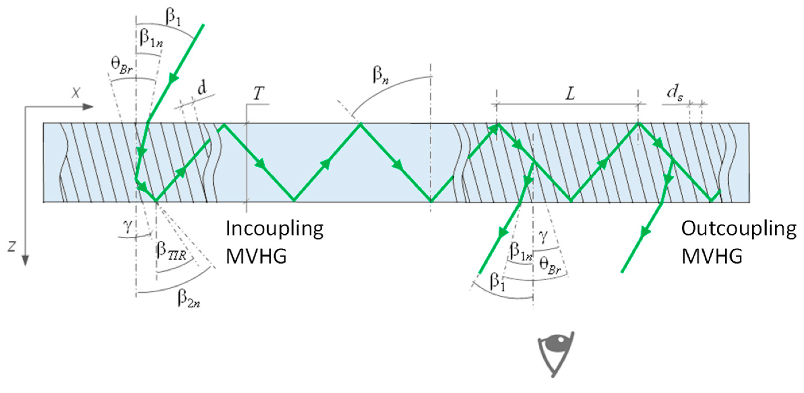
Figure 1 illustrates. In contrast to most of the solutions suggested in literature, in the case of MVHGs, the slant angle of volume diffraction gratings must be considered. Figure 1 shows the coupling conditions for incident and propagated radiation for a single MVHG forming part of the angular field of view when working in the transmission mode. The image, generated after the projector, is represented by a set of plane waves incident on the input coupler. A pair of incoupling and outcoupling MVHGs have the same phase profile geometry.
The incoupling and outcoupling DOE made of MVHGs have the same configuration for each of the MVHGs with number m, i.e., the same grating periods d1m = d2m and grating slant angles γ1m = γ2m. Along with the image output function, the output MVHGs expand the output pupil in the horizontal direction. Each pair of incoupling and outcoupling MVHGs is responsible for a part of the field of view in accordance with its angular selectivity. The incident field must locally satisfy the Bragg condition for each VHG according to the spectral-angular selectivity contour. The relationship between the specified direction of propagation of radiation inside the waveguide can be chosen arbitrarily, but for proper field composition for a certain spectral range, transmission MVHGs must have same surface periodicity; ds: the period of volume diffraction gratings in the plane of the surface of the waveguide—ds must be the same for the entire transformed angular field. Due to these conditions, it is convenient to record the diffraction gratings using a phase mask in the form of a relief-phase diffraction grating with a period ds. In this case, the interference volume pattern is created by the interference of beams that diffracted on the phase mask [11,12]. Thus, the recording angles are the diffraction angles of the recording beam on the phase mask. The method of angular multiplexing using a phase mask is described in detail in [11]. From the Bragg condition and the cosine connection of the VHG period d and the phase mask period ds, the following expressions are correct
{ sin ( γ β 1 n ) = λ G 2 d n = sin ( β 1 n + β 2 n 2 β 1 n ) = sin β 2 n β 1 n 2 ; d = d s cos γ = d s cos β 1 n + β 2 n 2 = λ G 2 n sin β 2 n β 1 n 2 .
Thus, the radiation propagation angle β2n in the waveguide plate corresponds to the diffraction equation of radiation on the phase mask
β 2 n = arcsin ( sin β 1 λ G / d s n ) = arcsin ( sin β 1 n λ G n d s ) .
The propagation angle in the waveguide plate is limited by the TIR condition for one edge of the field and the slide angle for the second edge of the field: βslide < β2n < βTIR. For the edge of the field bounded by the sliding angle βslide ≈ 90°, it is important to meet this condition so that the gaps between the TIR points were not too large when converting the output MVHG. The critical TIR angle is equal to βTIR = arcsin(1/n). The period of the phase mask is determined by the median condition for the angles of propagation and coordinates the directions of radiation propagation in the waveguide
d s λ n sin β 2 n
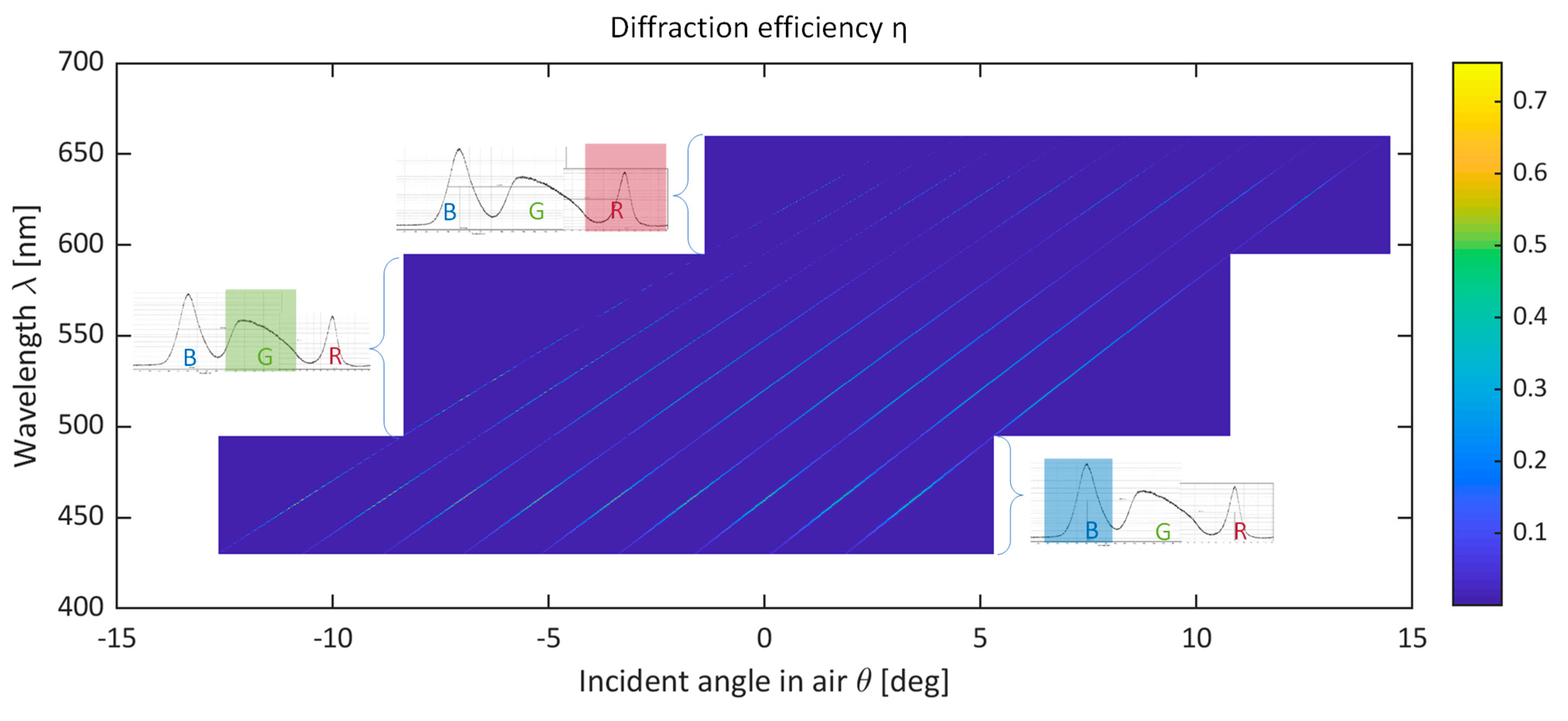
The spectral-angular bandwidth of the incoupling and outcoupling MVHGs determines the angular multiplexing step during the DOE recording. In turn, the spectral-angular selectivity of MVHGs in a wide spectral-angular range is affected by the width of the spectrum of the radiation source. 
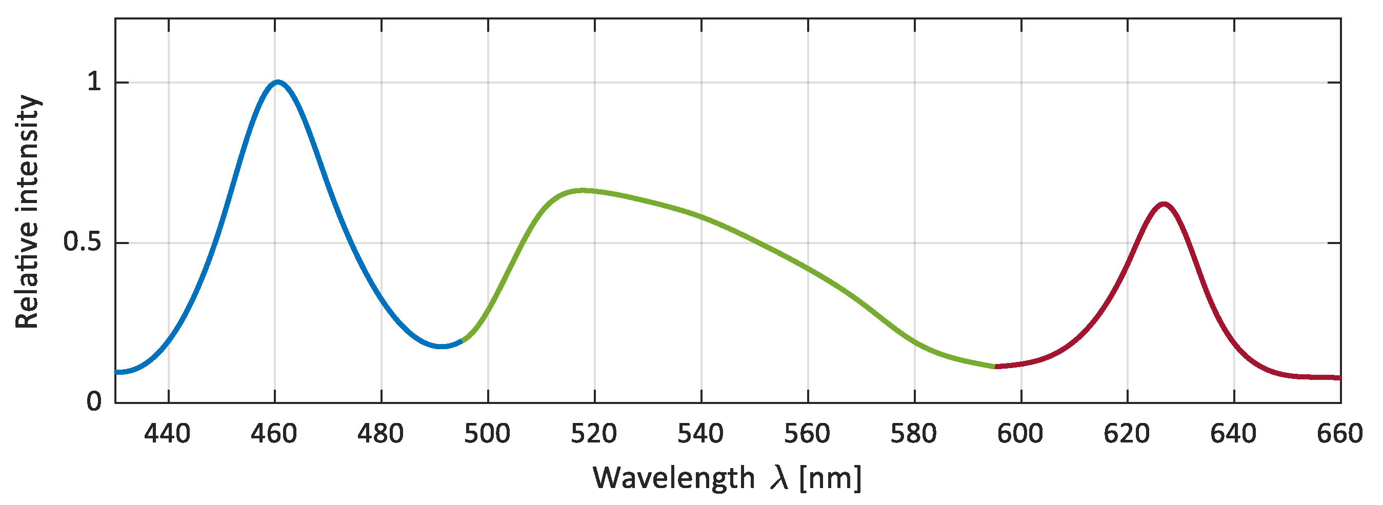
Figure 2 shows an example of the spectral characteristics of MiniRay projector used as a light source. Periods of phase masks for red (R), green (G) and blue (B) spectral ranges according to expression (3) are: ds R = 484 nm, ds G = 400 nm, ds B = 346 nm. The wider the spectral band in a particular spectral R/G/B channel is the larger the angular multiplexing step would be. The second condition that determines the angular multiplexing step is the allowable non-uniformity of the brightness of the image composed in the field of view. Main part of the research presented in the paper is about field of view composing for green spectral channel; the calculated parameters of corresponding MVHGs are in Appendix A.
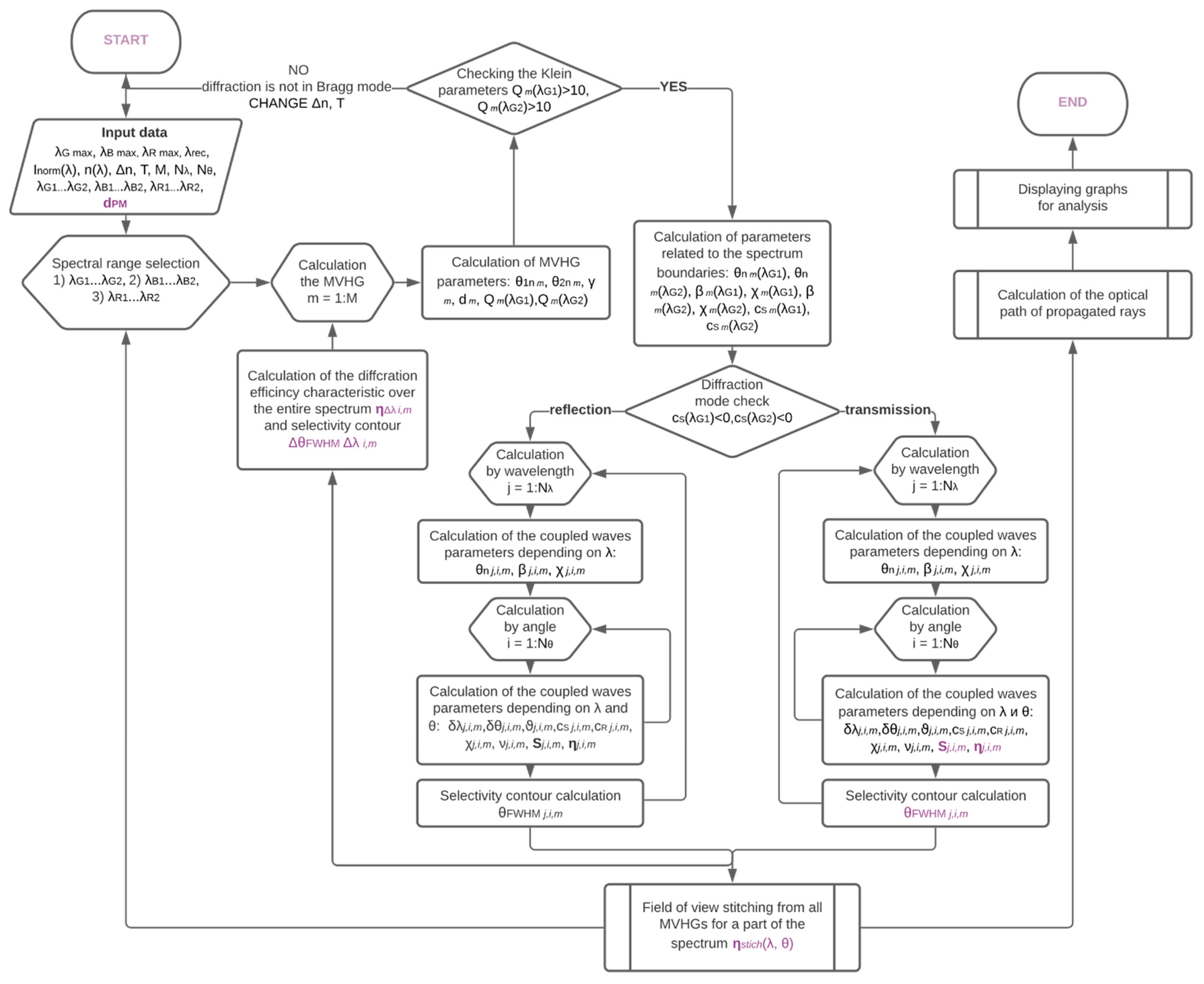
The second stage for prediction of the diffraction efficiency relations requires solving the diffraction problem on a volume periodic structure. Mathematical model of the diffraction on MVHGs is based on the Kogelnik coupled wave theory [13] and solves the problem of the field of view composition by a series of MVHGs. The calculation sequence is in Appendix B. Depending on the coupling conditions, diffraction gratings can operate in transmission or reflection modes. If the diffracted wave vector, projected onto a line containing the vector of the incident wave, is codirectional with the incident wave vector, then the grating is in a transmission mode. If they have opposite directions, the grating is reflective. Diffraction waveguide configuration under study utilizes transmission grating according to Equation (2). Diffraction efficiency of lossless transmission volume grating is defined by
η = sin 2 ( ν 2 + ξ 2 ) 1 + ξ 2 / ν 2 ;   ν = π n M T λ c R c S ,   ξ = ϑ T 2 c S ,
where ξ—the mismatch parameter (characterizes the selective properties of Bragg diffraction gratings); ν—the modulation parameter (characterizes the change in the parameters of the medium in the recording area, which forms the diffraction grating); cR = cosθM; cS = cosθM—K·cosγ; β—the angular coefficients; nN—modulation of the refractive index for an MVHG with number N; ϑ—the dephasing measure.
The modeling of multiplexing of elementary diffraction gratings should be corresponded to effective use of the refractive index modulation ∆n, which is responsible for the entire dynamic range of PTR glass. It is distributed by N-multiplexing to n1, n2,…, nN. The modulation of the refractive index is distributed according to the linear part of the exposure characteristics for the photosensitive material. Recommendations for the multiplexing procedure of the dynamic range are given in [14,15]. In particular, PTR glass has a wide quasilinear part of the exposure characteristics [11] and is suitable for multiplexing. The implemented mathematical model solves the diffraction problem for MVHGs with the arbitrary geometry and the sinusoidal phase profile and creates optical spectral or angular couplers.

3. Results

3.1. Diffraction Analysis for Green Light

This section considers MVHGs calculated for the image formation in the green part of the spectrum. The parameters for each MVHG are optimized for the calculated propagation direction responsible for the certain section of the angular field. The simulation result, which characterizes the DOE of the nine transmission MVHGs for nine-fold multiplexing, is shown in Figure 3. The angular multiplexing step for the illumination angle of the phase mask in the air was chosen to be Δθ ≈ 2.5°, which corresponds to the fulfillment of the Bragg condition for the spectral range boundaries while providing a relative brightness difference of up to 20%. The thickness of the waveguide was 2 mm, the full refractive index modulation was ∆n = 5 × 10⁻⁴, the dispersion characteristics were n(λ) = 4332*λ−2 + 1.48. Figure 3a shows the spectral-angular diagram, each bright selectivity line corresponds to the transformation of a part of the angular field. The angular selectivity contour for transmission gratings is a function of the sine square according to the coupled waves theory.
Diffraction efficiency is closely related to angular and spectral selectivity in Bragg diffraction: if there is a slight mismatch of a wavelength or an angle of incidence, the diffraction efficiency decreases rapidly according to the selectivity contour, as shown in Figure 3b, which shows a horizontal section of the spectral-angular diagram in Figure 3a. The selectivity contour changes from one multiplexed grating to another and becomes wider as the incident angles increase. When using a laser (spectrum width < 1 nm) as a hypothetical radiation source for mapping, the formed field of view by full width half maximum (FWHM) is ΔθFWHM(λ = 520nm) ≈ 0.03°. The angular band varies more than four times from 32″ to 2′24″ from the first to the last of the MVHGs. In this case, the diffraction efficiency ηmax decreases from 68% to 47% while the contour is widened. Increase in the number of multiplexing steps leads to a decrease in the diffraction efficiency while maintaining the thickness of the photosensitive layer (the thickness of the PTR plate), because less refractive index modulation is used to create one MVHG.
However, when using the same color evolved by a LED source with a band of about 40 nm (Figure 2), the angular band increases up to ΔθFWHM ≈ 3°, as shown in Figure 3c, which represents the diagonal cross section of the diagram shown in Figure 3a. Thus, a 100-fold increase in the field of view without changing the refractive index of the waveguide or the refractive index modulation ability provides a wide spectral characteristic. However, this occurs with loss of color uniformity: lower angles (left side of the field of view) contribute to the lower wavelength limit formation (500 nm), and higher angles (right side of the field of view) contribute to the upper wavelength limit formation (560 nm). This color inhomogeneity in the field of view is a disadvantage of the proposed solution based on selective MVHGs.

3.2. Diffraction Analysis for White Light

This section considers the transformation of blue and red light by means of DOE designed for the green light. Analysis, similar to that represented in Figure 3, is shown in Figure 4. For both blue and red spectrum regions, there is an increase in the non-uniformity of the diffraction efficiency due to the narrow spectral characteristic (Figure 2) compared to the non-uniformity for green light at the selected multiplexing step. For the green part of the spectrum, the non-uniformity at the selected angular multiplexing step is about 20%, the greatest non-uniformity in the composed field of view is observed for the blue part of the spectrum and is about 50%. In the case of ensuring uniformity for secondary spectrum parts, it is necessary to reduce the multiplexing step by up to 3 times.
Figure 5 illustrates the combined spectral-angular diagram for white light from three spectral channels of the MiniRay projector. The continuation of the diffraction bands at the junction of the spectral ranges confirms the field composition correctness of the MVHGs transfer functions. When forming an image, a shift of the blue spectral part towards negative radiation incidence angles could be expected alongside a shift of the red region towards the positive angles. When creating augmented reality displays based on MVHGs, it is recommended to choose LED sources with a wide spectral band, which is confirmed by the simulation results.

4. Discussion

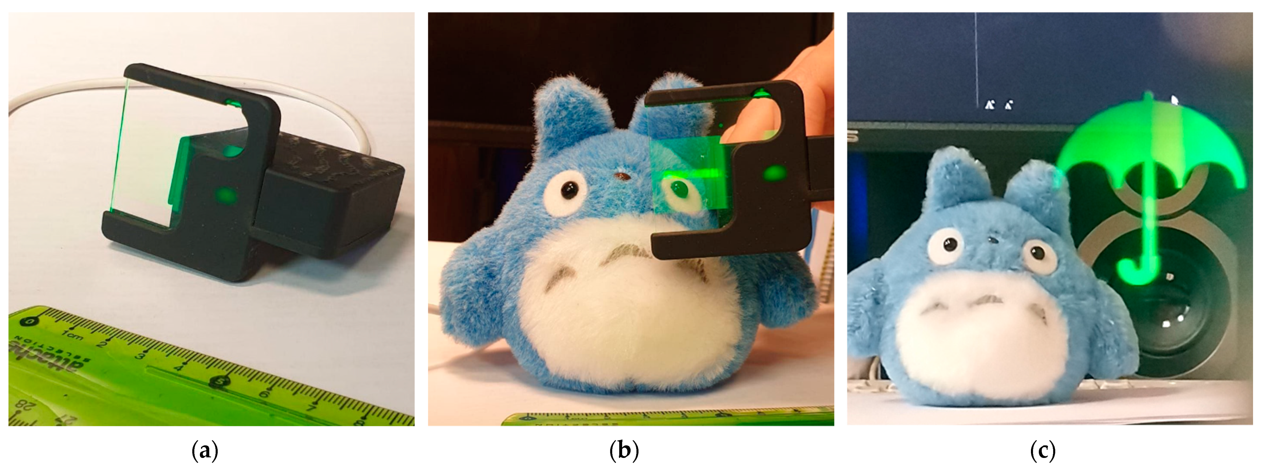
To test the abovementioned methods, a prototype of augmented reality monocular was manufactured. 
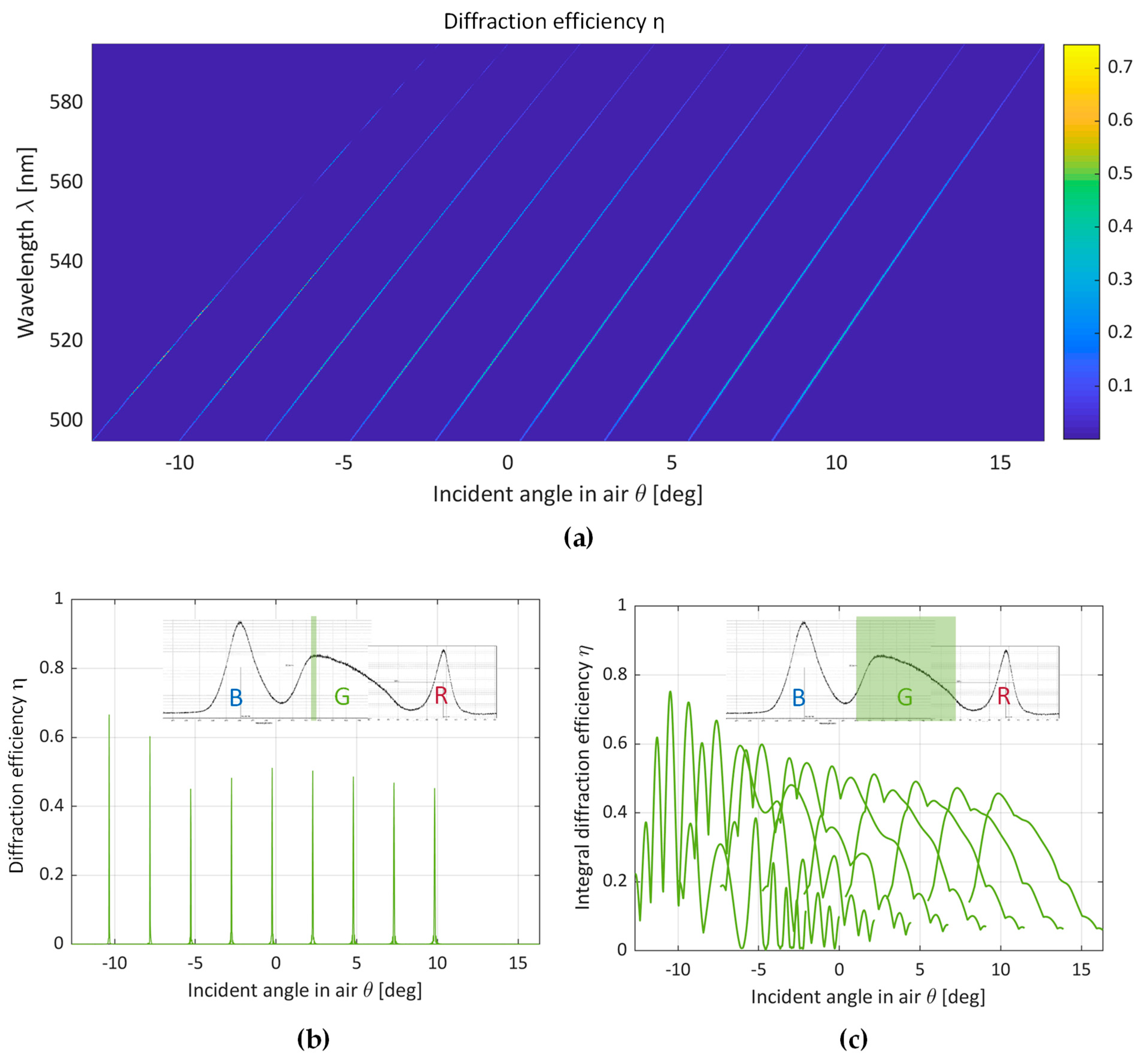
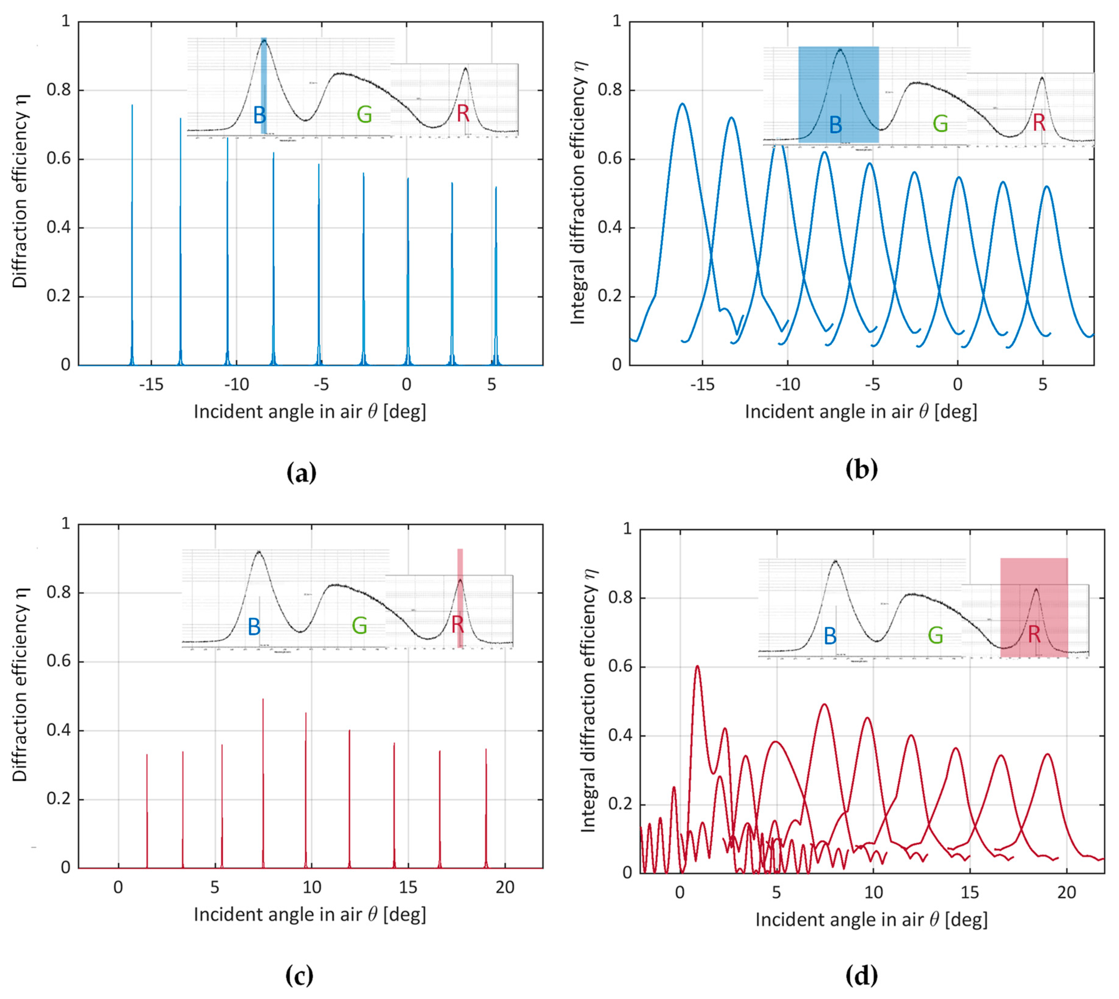
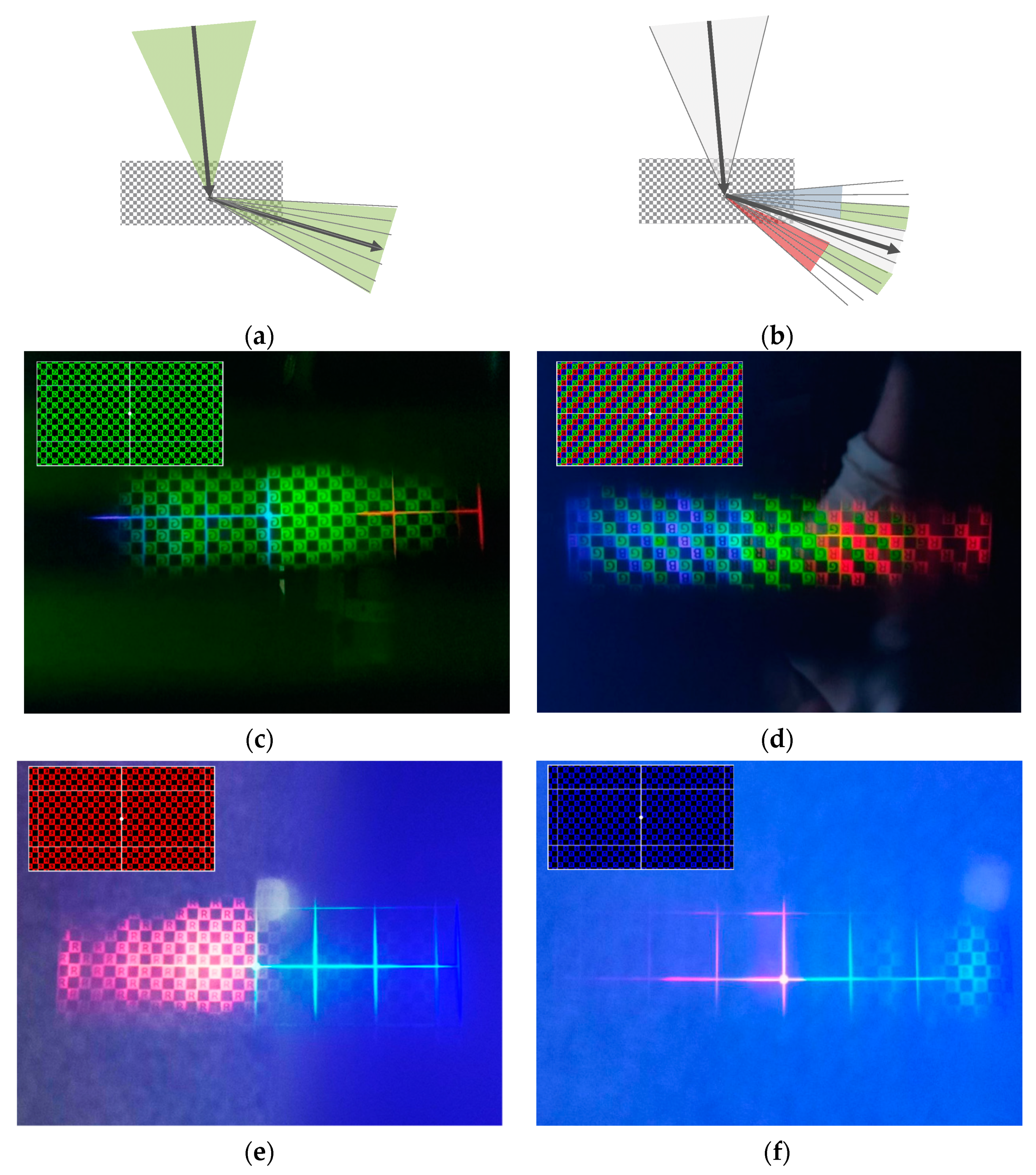
Figure 6 illustrates the prototype. When using volume diffraction gratings in PTR glass, only angular multiplexing allows expansion of the effective angular field of view provided by a single diffraction grating, as shown in Figure 7a,b for monochrome green and multicolor implementation, respectively. The action of each sequential MVHG can be interpreted as a static implementation of the “rolling K-vector” conditions used in switchable DOEs [7]. The parameters of the MVHG structure are optimized for rotation of the diffraction angle, which results in transformation of the angular selectivity contour of each subsequent MVHG. The optical system of the prototype contains a single-layer diffraction waveguide made of PTR glass with integrated volume DOE formed by MVHGs. The diffraction waveguide was made by a two-stage recording method by angular multiplexing in PTR glass using a phase mask. In the first stage, a phase mask in the form of the relief-phase diffraction grating in a photoresist was applied to the waveguide; in the second stage, phase volume DOE was obtained in the bulk of the waveguide in the form of superimposed MVHGs by angular multiplexing through the phase mask with UV radiation that was actinic for PTR glass.
The prototype uses the compact commercial projector MiniRay as an image generation module (Figure 2). Figure 7c,d show images of technical tables illustrating the composed angular field of 23° and 32°, respectively. Images of red and blue technical tables in a brighter environment are presented in Figure 7e,f. The angular bandwidth provided by the selectivity contours for a particular wavelength determines the angular resolution limit for the generated image, and also sets requirements for the waveguide wedge. The total angular shift in the plate by TIR propagation from the incoupling DOE to the outcoupling DOE should not exceed a half of the width of the diffraction band. There is a tendency to compensate for the number of reflections (TIR): the ΔθFWHM band is wider for rays propagating in the substrate at smaller angles having a larger number of reflections.
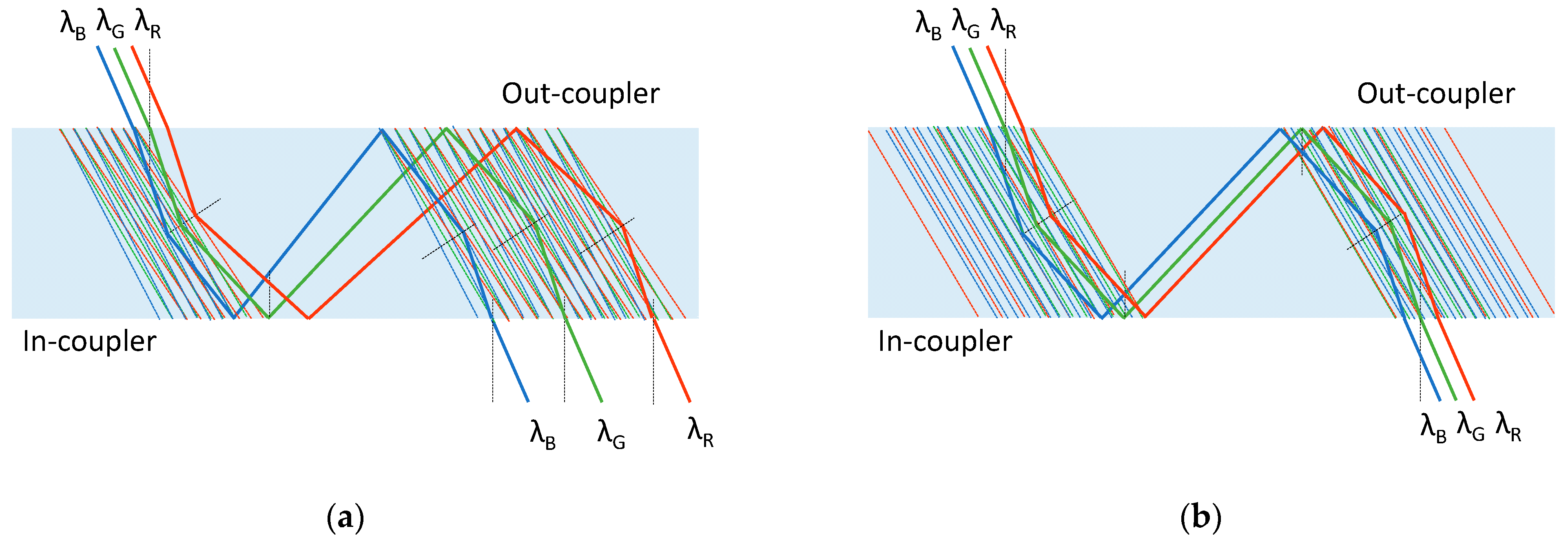
Figure 8a shows the formation of a color point by MVHGs based on one surface periodicity calculated for one spectral wavelength: rays of different spectral channels enter the waveguide at different propagation angles. Prospects for the use of integrated diffraction waveguides based on selective MVHGs are in the implementation of a full-color diffractive waveguide with eliminated chromatism, shown in Figure 8b. To form a full-color image, it is necessary to form diffraction elements that coordinate the light-guiding directions by the field of view parts and by the spectrum. The filtering properties of MVHGs can eliminate chromatism in the image of an augmented reality device, limiting its bandwidth to the spectral selectivity contour to 10 nm.
The non-uniformity and angular field of view of the projected image is regulated by the parameters of angular multiplexing that are chosen in accordance with the spectral-angular selectivity of MVHGs. At the same time, the contours of spectral and angular selectivity affect the resolution both in terms of the spectrum and the angle.

Author Contributions

Conceptualization, methodology, resources S.O. and V.V.; resources, phase mask recording, investigation and formal analysis D.L.; multiplexed volume holographic grating recording, software, investigation and data curation M.S. and A.Z.; investigation and visualization Y.K.; writing—original draft preparation M.S.; formal analysis, supervision, project administration, and funding acquisition S.O.; writing—review and editing, validation V.V. All authors have read and agreed to the published version of the manuscript.

Funding

This research received no external funding.

Institutional Review Board Statement

Not applicable.

Informed Consent Statement

Informed consent was obtained from all subjects involved in the study.

Data Availability Statement

The data presented in this study are available on request from the corresponding author. The data are not publicly available due to future anti-plagiarism check during thesis defense.

Acknowledgments

The authors acknowledge the support by Vladimir Markin for the investigation process, Dmitrii Kuzmin, Pavel Khanevich and Ekaterina Drozdova for their help in technical issues. The authors thank Nikolay Nikonorov and Sergey Ivanov for valid consultations on photo-thermo-refractive glass.

Conflicts of Interest

The authors declare no conflict of interest.

Appendix A

Table A1 presents the parameters of the MVHGs and their recording angles, which are used for image formation in the green spectral channel. For structures with these parameters, the diffraction problem was solved and experiments on angular multiplexing were performed.

Appendix B

The calculation sequence for the mathematical model is shown in Figure A1. The mathematical model presented in this paper solves the diffraction problem for composing angular field of view by reflection or transmission MVHGs. The diffraction mode is determined from the given conditions for incidence and propagation direction coordinated by the surface periodicities of MVHGs.
Table A1. Calculation results for MVHGs used in green spectral channel in diffraction waveguide.

m
Incident Angle β1 [deg]Propagation Angle β2n [deg]Grating Slant Angle γ [deg]Volume Period d, [μm]TIR Step L [mm]Optical Path in TIR Step X [mm]Recording Angles of UV Beams after the Phase MaskRecording Angle of UV Beam α1 [deg]
α1n [deg]α2n [deg]
1−12.5−76.47−42.3930916.6217.10−21.90−62.88−34.01
2−10−70.68−38.6732711.4112.09−19.33−58.01−29.77
3−7.5−66.19−35.603419.079.91−17.06−54.14−26.10
4−5−62.37−32.853527.648.63−14.93−50.78−22.73
5−2.5−58.97−30.323626.657.76−12.89−47.75−19.55
60−55.88−27.943705.907.13−10.92−44.96−16.51
72.5−53.01−25.673785.316.65−9.00−42.34−13.57
85−50.33−23.503844.826.26−7.12−39.87−10.72
97.5−47.79−21.403904.415.95−5.28−37.53−7.93
1010−45.40−19.373954.065.70−3.47−35.28−5.21
1112.5−43.12−17.414003.745.48−1.69−33.13−2.53
1215−40.93−15.504043.475.290.07−31.060.10
Figure A1. Flow chart of mathematical modeling for MVHGs based on coupled wave theory.
Photonics 08 00232 g0a1

References

  1. Lee, Y.-H.; Zhan, T.; Wu, S.-T. Prospects and challenges in augmented reality displays Virtual Real. Intell. Hardw. 2019, 1, 10–20. [Google Scholar] [CrossRef]
  2. Kress, B.C. Optical Architectures for Augmented-, Virtual-, and Mixed-Reality Headsets; SPIE Press: Bellingham, WA, USA, 2020. [Google Scholar]
  3. Putilin, A.N.; Morozov, A.V.; Kopenkin, S.S.; Dubynin, S.E.; Borodin, Y.P. Holographic Waveguide Periscopes in Augmented Reality Displays. Opt. Spectrosc. 2020, 128, 1828–1836. [Google Scholar] [CrossRef]
  4. Levola, T.; Laakkonen, P. Replicated slanted gratings with a high refractive index material for in and outcoupling of light. Opt. Express 2007, 15, 2067–2074. [Google Scholar] [CrossRef] [PubMed]
  5. Grad, Y.A.; Shishova, M.V.; Odinokov, S.B.; Solomashenko, A.B.; Yanev, A.S.; Nikolaev, V.V.; Anikeeva, A.A. Analysis of holographic lightguide’s optical parameters for AR devices. Proc. SPIE 2018, 10818, 108181W. [Google Scholar]
  6. Draper, C.T.; Bigler, C.M.; Mann, M.S.; Sarma, K.; Blanche, P.-A. Holographic waveguide head-up display with 2-D pupil expansion and longitudinal image magnification. Appl. Opt. 2019, 58, A251–A257. [Google Scholar] [CrossRef] [PubMed]
  7. Han, J.; Liu, J.; Yao, X.; Wang, Y. Portable waveguide display system with a large field of view by integrating freeform elements and volume holograms. Opt. Express 2015, 23, 3534–3549. [Google Scholar] [CrossRef] [PubMed] [Green Version]
  8. Waldern, J.D.; Grant, A.J.; Popovich, M.M. DigiLens switchable Bragg grating waveguide optics for augmented reality applications. Proc. SPIE 2018, 10676, 106760G. [Google Scholar]
  9. Klyukin, D.; Ivanov, S.; Krykova, V.; Silvennoinen, M.; Svirko, Y.; Nikonorov, N. Thermal stability of volume Bragg gratings in chloride photo-thermo-refractive glass after femtosecond laser bleaching. Opt. Lett. 2018, 43, 1083–1086. [Google Scholar] [CrossRef] [PubMed]
  10. Sgibnev, Y.; Nikonorov, N.; Ignatiev, A.; Vasilyev, V.; Sorokina, M. Photostructurable photo-thermo-refractive glass. Opt. Express 2016, 24, 4563–4572. [Google Scholar] [CrossRef] [PubMed]
  11. Shishova, M.V.; Zherdev, A.Y.; Lushnikov, D.S.; Odinokov, S.B. Recording of the Multiplexed Bragg Diffraction Gratings for Waveguides Using Phase Mask. Photonics 2020, 7, 97. [Google Scholar] [CrossRef]
  12. Park, T.-H.; Kim, S.-M.; Oh, M.-C. Polymer-waveguide Bragg-grating devices fabricated using phase-mask lithography. Curr. Opt. Photonics 2019, 3, 401–407. [Google Scholar]
  13. Kogelnik, H. Coupled wave theory for thick hologram gratings. Bell Syst. Tech. J. 1969, 48, 2909–2947. [Google Scholar] [CrossRef]
  14. Zhai, Q.; Tao, S.; Zhang, T.; Song, X.; Wang, D. Investigation on mechanism of multiple holographic recording with uniform diffraction efficiency in photopolymers. Opt. Express 2009, 17, 10871–10880. [Google Scholar] [CrossRef] [PubMed]
  15. Ingersoll, G.B.; Leger, J.R. Channel density and efficiency optimization of spectral beam combining systems based on volume Bragg gratings in sequential and multiplexed arrangements. Appl. Opt. 2015, 54, 6244–6253. [Google Scholar] [CrossRef] [PubMed]
Figure 1. Scheme of radiation propagation in a waveguide plate. Diffraction geometry for a pair of VHGs of the input and output couplers. Parameters: β1, β1n—incident angles in the air and in the waveguide relative to the normal to the plate surface; θBr—Bragg angle; βTIR—air defense angle; γ—angle of inclination of the diffraction grating; β2n—diffraction angle in the waveguide and the propagation angle relative to the normal to the plate surface; d—the volume grating period; ds—the surface period (period of the phase mask during the recording); T—thickness of the waveguide; L—length between the TIR points.
Photonics 08 00232 g001
Figure 2. Spectral characteristics of MiniRay compact projector.
Photonics 08 00232 g002
Figure 3. MVHGs diffraction efficiency analysis: (a) Spectral-angular diagram of diffraction efficiency; (b) Diffraction efficiency selectivity contours for spectral maximum; (c) Diffraction efficiency selectivity contours for a wide spectrum.
Photonics 08 00232 g003
Figure 4. MVHGs diffraction efficiency analysis for blue light: (a) Selectivity contours for spectral maxima and (b) wide spectrum. MVHGs diffraction efficiency analysis for red light: (c) Selectivity contours for spectral maxima and (d) wide spectrum.
Photonics 08 00232 g004
Figure 5. Spectral-angular diagram for the full spectrum of the MiniRay projector.
Photonics 08 00232 g005
Figure 6. Prototype: (a) appearance; (b) illustration of the waveguide transparency; (c) illustration of augmented information added to the real view.
Photonics 08 00232 g006
Figure 7. Formation of a composite angular field of view by MVHGs based on one surface period: (a) for green light and (b) white light. Field of view represented by angular tables: (c) for green light and (d) white light. Field of view in brighter environments: (e) for red light and (f) blue light.
Photonics 08 00232 g007
Figure 8. Formation of a color point: (a) by MVHGs based on one surface periodicity in the waveguide, (b) by MVHGs based on three surface periodicities.
Photonics 08 00232 g008
Publisher’s Note: MDPI stays neutral with regard to jurisdictional claims in published maps and institutional affiliations.

