Article

Color Digital Holography Based on Generalized Phase-Shifting Algorithm with Monitoring Phase-Shift

School of Electronic and Electrical Engineering, Kyungpook National University, 80 Daehak-ro, Buk-Gu, Daegu 41566, Korea
*
Author to whom correspondence should be addressed.
Photonics 2021, 8(7), 241; https://doi.org/10.3390/photonics8070241
Submission received: 31 May 2021 / Revised: 24 June 2021 / Accepted: 25 June 2021 / Published: 28 June 2021
(This article belongs to the Special Issue Holography)

Abstract

:
Color digital holography (DH) has been researched in various fields such as the holographic camera and holographic microscope because it acquires a realistic color object wave by measuring both amplitude and phase. Among the methods for color DH, the phase-shifting DH has an advantage of obtaining a signal wave of objects without the autocorrelation and conjugate noises. However, this method usually requires many interferograms to obtain signals for all wavelengths. In addition, the phase-shift algorithm is sensitive to the phase-shift error caused by the instability or hysteresis of the phase shifter. In this paper, we propose a new method of color phase-shifting digital holography with monitoring the phase-shift. The color interferograms are recorded by using a focal plane array (FPA) with a Bayer color filter. In order to obtain the color signal wave from the interferograms with unexpected phase-shift values, we devise a generalized phase-shifting DH algorithm. The proposed method enables the robust measurement in the interferograms. Experimentally, we demonstrate the proposed algorithm to reconstruct the object image with negligibly small conjugate noises.

Graphical Abstract

1. Introduction

Color digital holography (DH) receives great interest since it has the outstanding advantage to measure and reconstruct realistic color objects [1,2,3]. This technique is expected to be useful for many applications such as the holographic microscope, holographic camera, and holographic inspection system [4,5,6,7]. The DH has intrinsic characteristics of measuring both the phase and amplitude of the signal wave by interference phenomena [8,9]. Basically, the subtraction operation between two interferograms gets rid of the autocorrelation term and the amount of the movement of the interference patterns according to the phase-shift induce the phase information of the signal wave [10]. Therefore, the phase-shift algorithms give the information of the signal wave without the autocorrelation term and conjugate noise from more than two interferograms.
Most phase-shift algorithms for color DH require a set of interference patterns for each wavelength. In these methods, the increase of the number of interferograms is an important issue. Various methods of applying pixelated filter arrays to focal plane array (FPA) sensors have been reported [11,12,13,14]. T. Kakue proposed the phase-shifting color DH using an FPA with both the color filter array and polarizer array [15]. With this FPA sensor, six interferograms are captured in a single shot. These six interferograms consist of three sets according to wavelengths, each of which has two phase-shifts. However, this method has the disadvantage that it is hard to measure high spatial frequency because the sampling positions are different by two or three pixels at the FPA. Compared with the case that the sampling position of interferograms does not change, this method has a relatively small spatial bandwidth.
In practice, it is difficult to precisely shift the phase due to the instability or hysteresis of the phase shifter. To solve this problem, some methods of estimating the phase-shift values have been studied [16,17,18,19]. L. Z. Cai proposed a method to estimate the phase in the special case that the phase of the signal is a uniformly distributed random value [20,21]. In another study, the phase is estimated by using the fact that the conjugate noise becomes dominant when the phase-shift is incorrectly estimated [22]. However, these methods demand huge computational resources to calculate the cost function each time during iteration. Alternatively, the methods directly monitoring the phase change require some complicated optical configuration, but they have the advantage of reducing the computational burden and allowing an accurate phase-shift to be measured [23,24].
In this paper, we propose a new method of color digital holography. The interferograms for two wavelengths are simultaneously measured using an FPA sensor with a Bayer color filter array attached. Due to the color filter array, there is one pixel difference for different wavelengths in the FPA where signal waves are sampled. Different wavelengths do not interfere with each other, so there is no loss in spatial bandwidth for reconstructing the image. Therefore, the signal waves for both wavelengths are measured with four-step phase-shifting simultaneously. In order to shift the phase, a PZT actuator with a mirror attached is used. For monitoring, a Mach–Zehnder interferometer is inserted at the signal arm, and the actual phase-shift value is obtained by measuring the movement of the fringe pattern. This measurement is usually different from the desired phase-shift, and it is difficult to apply a phase-shifting DH algorithm with phase-shifts of regular intervals. Therefore, in this paper, we devise a generalized phase-shifting DH algorithm that is applicable to the case of an arbitrary phase-shift.
This paper is organized as follows. In Section 2, the setup of the proposed system is explained, and the numerical reconstruction in the color DH with a Bayer color filter is discussed. In Section 3, the method of monitoring the phase-shift is explained, and a generalized phase-shifting algorithm is described. In Section 4, experiment results are presented and discussed. In Section 5, a conclusion is presented.

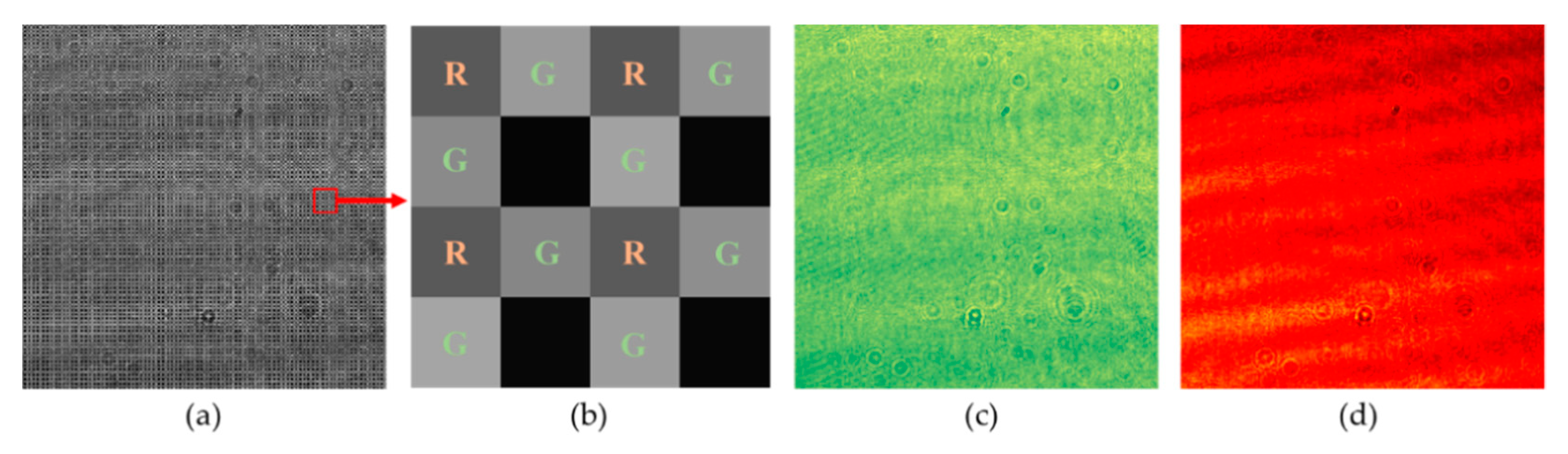
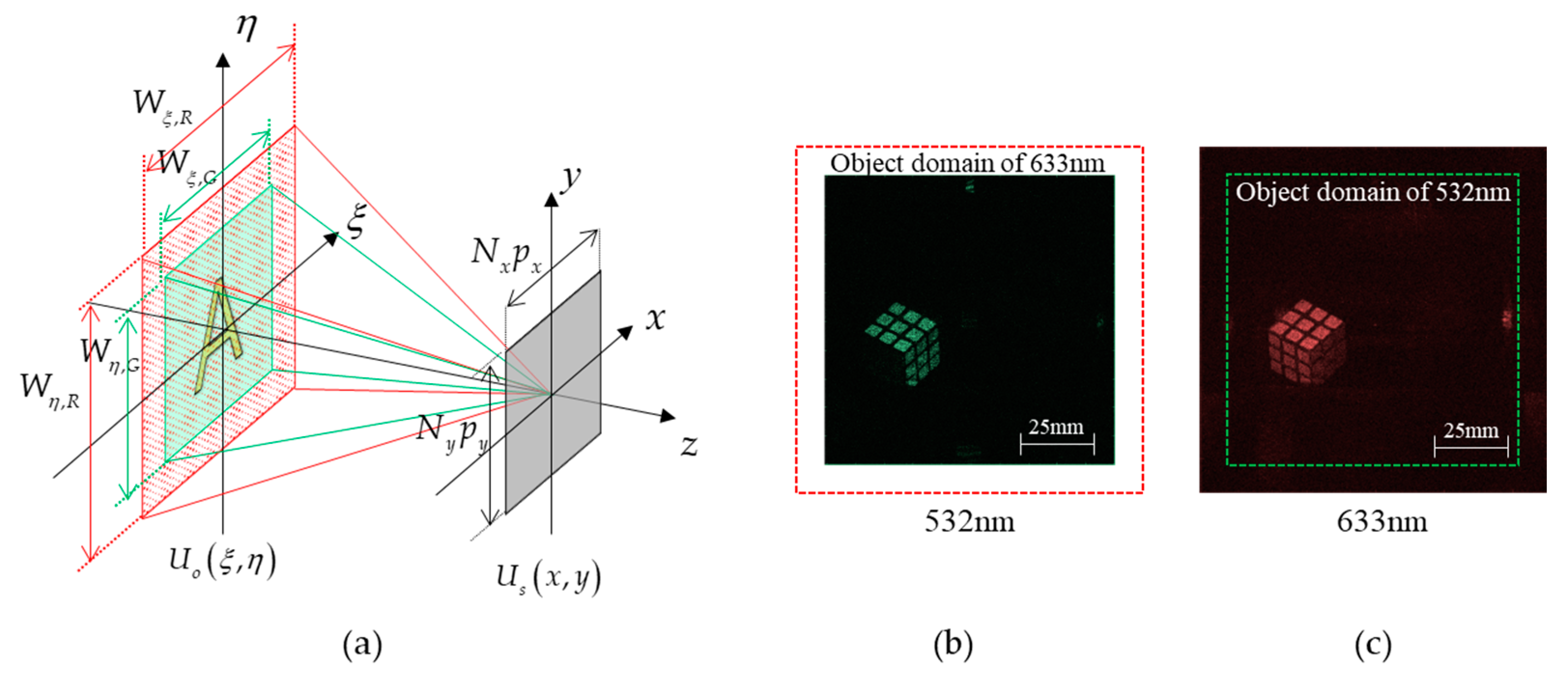
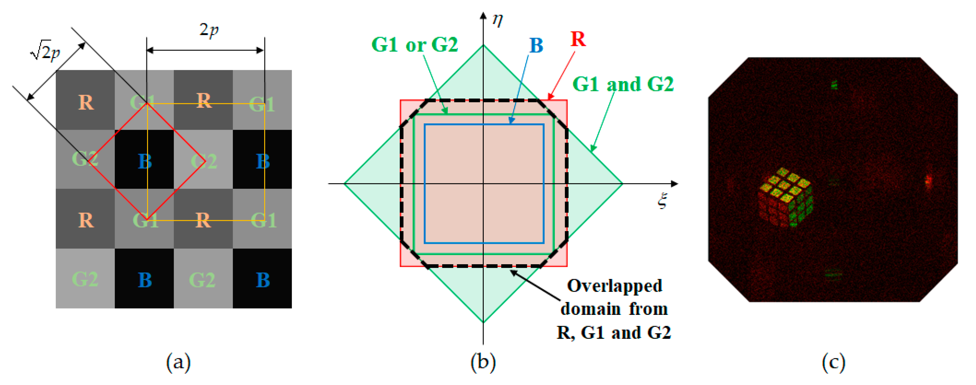
2. Color Phase-Shifting Digital Holography with Bayer Color Filter

We use an FPA sensor with a Bayer color filter array to measure the color interferograms. The FPA sensor measures the signals for two wavelengths simultaneously with the help of the Bayer color filter. Figure 1 shows the schematic diagram of the proposed color phase-shifting DH system with two wavelengths. The system consists of an interferometer for color phase-shifting DH and a Mach–Zehnder interferometer for monitoring. Red and green lasers are used as the light sources. In the interferometer for color phase-shifting DH, optical waves from two lasers are divided into the reference arm and signal arm. In the signal arm, the phase of the optical wave is shifted by the PZT actuator with the mirror attached, and then the light illuminates the objects. The signal wave reflected from the objects interferes with the reference wave at FPA1, and the color interferogram is obtained. The Mach–Zehnder interferometer is inserted in the signal arm and the optical wave is divided into two branches. The optical phase in one branch is shifted by the PZT actuator and then it is interfered with the optical wave in the other branch at the FPA2. It is noted that the red optical wave is filtered out by the color filter in front of the FPA2 and that the fringe pattern of the green optical wave is measured by the FPA2. From the green fringe pattern, the phase-shifts are computed.
The interferograms of red and green wavelengths are obtained by the FPA1 at the same time. Figure 2 shows how red and green interferograms are separated from the raw image. The Bayer color filter array is composed of red, green, and blue color filters alternatively arranged. In this paper, we use only red and green light sources for verifying the feasibility of our method. Although the number of pixels in the green filter array is twice that of the red filter array, only half the number of pixels in the green filter array is used to make the sampling interval of red and green same. Sampled red and green interferograms are respectively shown in Figure 2c,d.
Figure 3 shows the difference of the size in object domain when color DH is captured by the FPA1 with the same sampling interval for red and green. The geometry of color DH is shown in Figure 3a where the object wave U o ( ξ , η ) propagates to the FPA1 plane and then the signal wave U s ( x , y ) is captured. The relation between the object wave and the signal wave is described by Fresnel propagation as follows:
U s ( x , y ) = 1 j λ z exp ( j 2 π z λ ) exp [ j π λ z ( x 2 + y 2 ) ] F { U o ( ξ , η ) exp [ j π λ z ( ξ 2 + η 2 ) ] } | f ξ = x λ z , f η = y λ z .
Here, λ is the wavelength and z is the propagation distance from the object plane to the FPA1 plane. Since the signal wave is sampled at the FPA1 by the interval ( p x , p y ) in x and y directions, respectively, the reconstructed object wave also is represented as a discrete function given by
U o ( n ξ Δ ξ , n η Δ η ) = 1 j λ z exp ( j 2 π z λ ) exp [ j π λ z ( n ξ 2 Δ ξ 2 + n η 2 Δ η 2 ) ] × n x n y U s ( n x p x , n y p y ) exp [ j π λ z ( n x 2 p x 2 + n y 2 p y 2 ) ] exp [ j 2 π ( n x n ξ N x + n y n η N y ) ] ,
where the sample spacings of the object function are determined by Δ ξ = λ z / N x p x and Δ η = λ z / N y p y from discrete Fourier transform. N x and N y mean the numbers of sampling in x and y directions, respectively. Thus, the size of the reconstructed object image is limited by these sampling numbers and the maximum widths in x and y directions are given by
W x = Δ ξ N x = λ z p x ,
  W y = Δ η N y = λ z p y .
These widths are equal to the size of the object domain measured by the FPA1 without an aliasing problem since the propagation distance is sufficiently longer than the size of the FPA1. Since W x and W y depend on the wavelength, the widths for red and green wavelengths are related to the ratio of the wavelengths as follows:
W x , R = λ R λ G W x , G
W y , R = λ R λ G W y , G
Therefore, it is obvious that the widths of the reconstructed object image are different in red and green wavelengths as shown in Figure 3b,c.

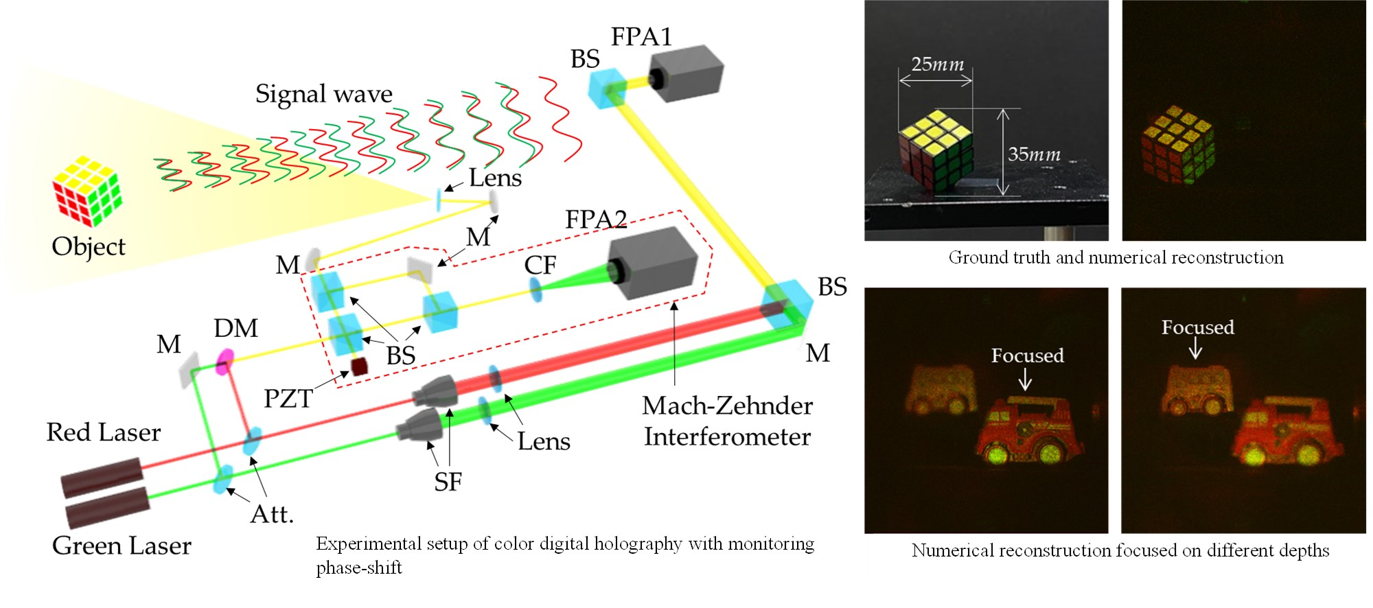
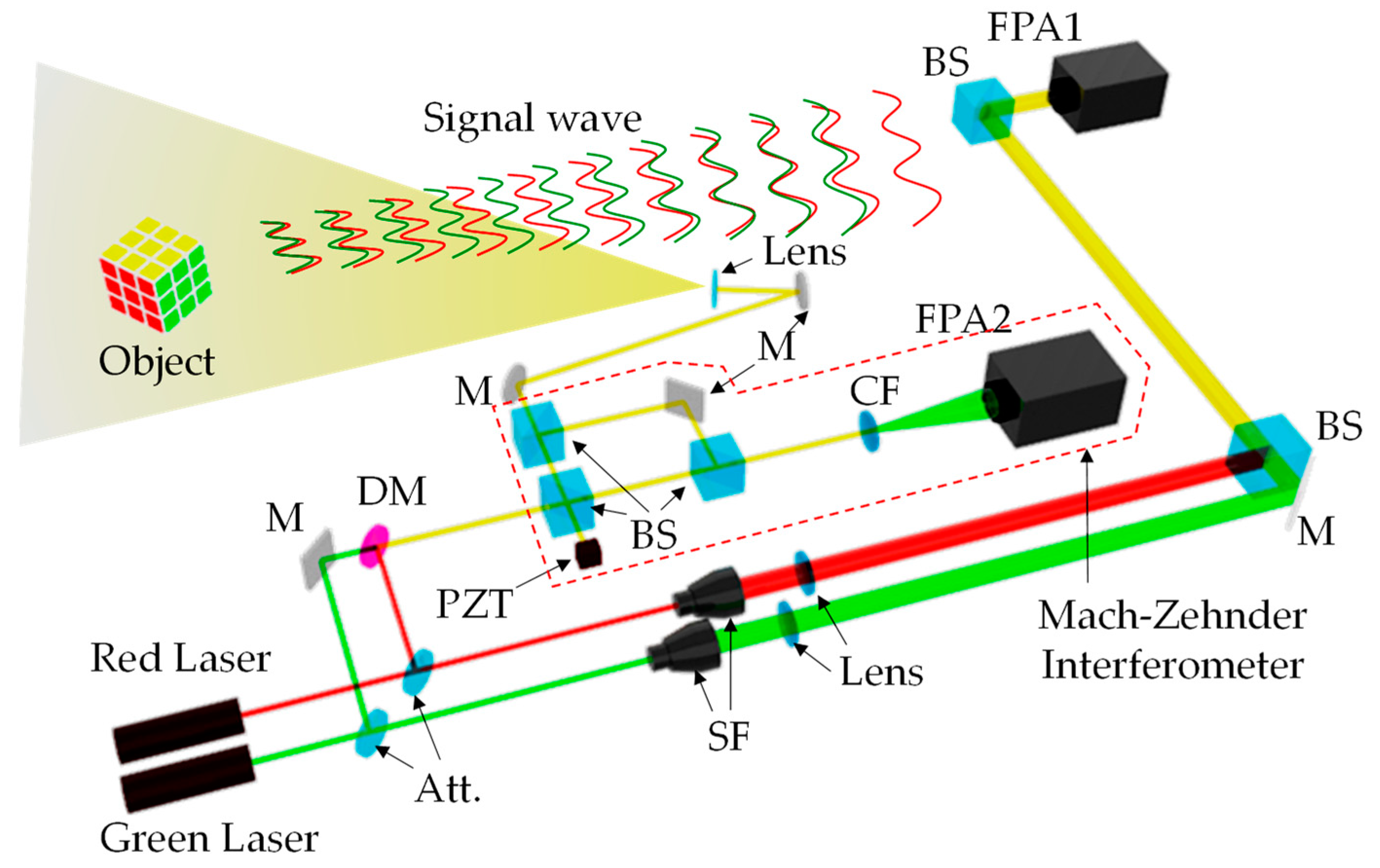
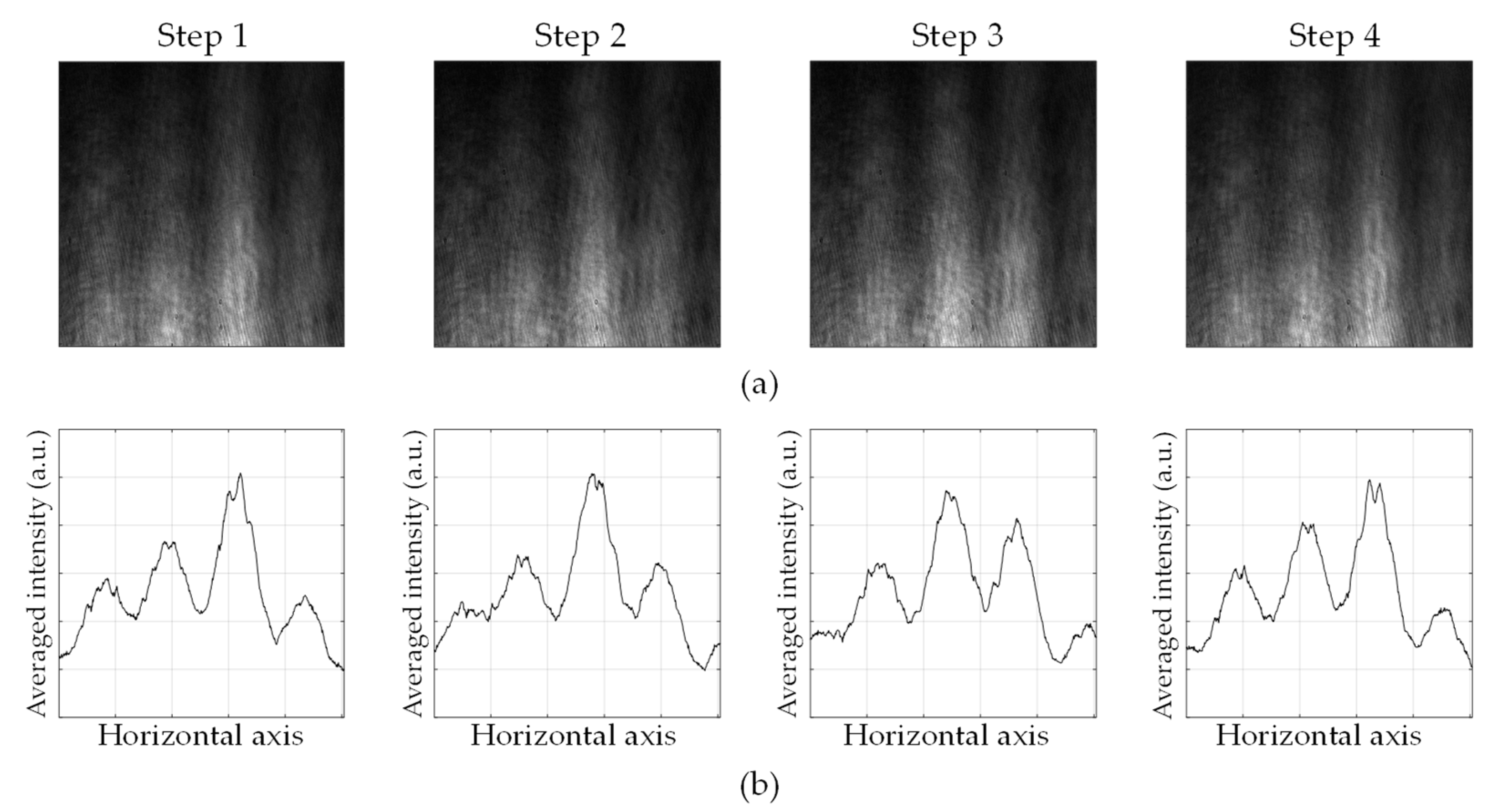
3. Generalized Phase-Shifting Algorithm with Monitoring Phase-Shift

In our system, the Mach–Zehnder interferometer is inserted to measure actual phase-shifts. The signal arm is divided into two branches by a beam splitter. Among them, one is shifted the phase by the PZT actuator. Then, the interference between two beams is captured at the FPA2 right after the color filter that makes the only green wavelength pass. It makes a vertical fringe pattern as shown in Figure 4. The fringe pattern moves according to the phase-shift. Figure 4a shows fringe patterns corresponding to each step and the graphs in Figure 4b are the average of fringe patterns in vertical directions.
The wave function of the fringe pattern is simply represented by
U f r i n g e = A f r i n g e exp [ j ( α + 2 π m p m / Λ ) ] .
Here, Λ is the period of the fringe resulting from a small difference in the angle between the two incident waves. p m is the pixel pitch of the FPA2 and m is the order of the pixel in a horizontal direction. A f r i n g e is the amplitude distribution of the wave function of the fringe pattern. It is noted that the fringe pattern is moved with respect to a phase-shift, α. The phase-shifts can be interpreted as the degree of movement of the acquired fringe patterns, and here we use the Fourier transform. In the Fourier transform of the fringe pattern, the phase of the specific frequency corresponding to the period, Λ is extracted [25]. Then, the phase-shift in the green wavelength is calculated from the ratio of the amount of the movement to the period. Since the PZT actuator with mirror attached is used as a phase-shifter, the phase-shift in the red wavelength is obtained from the phase-shift in the green wavelength as follows:
α i , R = λ G λ R α i , G .
The actual phase-shifts computed from the fringe pattern in the monitoring interferometer are different from the desirable phase-shifts of regular intervals. So, a generalized phase-shifting algorithm is necessary to calculate the signal wave from the interferograms in the color DH interferometer. A generalized phase-shift algorithm is induced from the assumption that the phase-shifts are arbitrary values.
The interferogram between the signal wave and the reference waves of the form
U s = A s exp ( j θ s ) ,
U r , i = A r exp ( j α i )
is recorded on the FPA1. Here, A s   and θ s represent the amplitude and the phase of the signal wave. A r is the amplitude of the reference wave and α i is the phase-shift by the PZT actuator. In our experiment, the intensity of the reference wave is priorly measured with FPA1. Then, the amplitude is obtained by taking the square root of the intensity. It is noted that the phase of the signal wave is shifted in experiments, but we expressed that the phase of the reference wave is shifted on the contrary. Then, the intensity of interferogram is given by
I i = | U s + U r , i | 2 = A s 2 + A r 2 + 2 A s A r cos ( θ s α i ) .
Most phase-shift algorithms are based on the subtraction of two interferograms in order to delete the autocorrelation term. Two subtractions are obtained from the four interferograms as follows:
I 1 I 3 = 2 A s A r [ cos ( θ s α 1 ) cos ( θ s α 3 ) ] ,
I 2 I 4 = 2 A s A r [ cos ( θ s α 2 ) cos ( θ s α 4 ) ] .
By using trigonometric formulas, the above simultaneous equations are represented in the matrix form as follows:
A s ( cos θ s sin θ s ) = 1 2 A r ( cos α 1 cos α 3 sin α 1 sin α 3 cos α 2 cos α 4 sin α 2 sin α 4 ) 1 ( I 1 I 3 I 2 I 4 ) .
At last, from the Euler’s formula, the signal wave is obtained by
U s = A s ( cos θ s + j sin θ s ) .
The conventional four-step phase-shifting DH with π / 2 interval is the most popular since the estimated signal wave is insensitive to the errors of the phase-shifts when the phase-shift difference in the pair of the interferograms is π. However, if the error is too large, it is difficult to accurately predict the signal wave. When the phase-shift difference of the pair of the interferograms is too far from π, the estimation of a signal wave becomes very sensitive under the assumption that a small phase-shift error exists [26]. In this paper, we propose a method of directly measuring the phase-shift using the Mach–Zehnder interferometer and the signal wave is obtained using the generalized phase-shifting DH algorithm for the accurate phase-shifts.

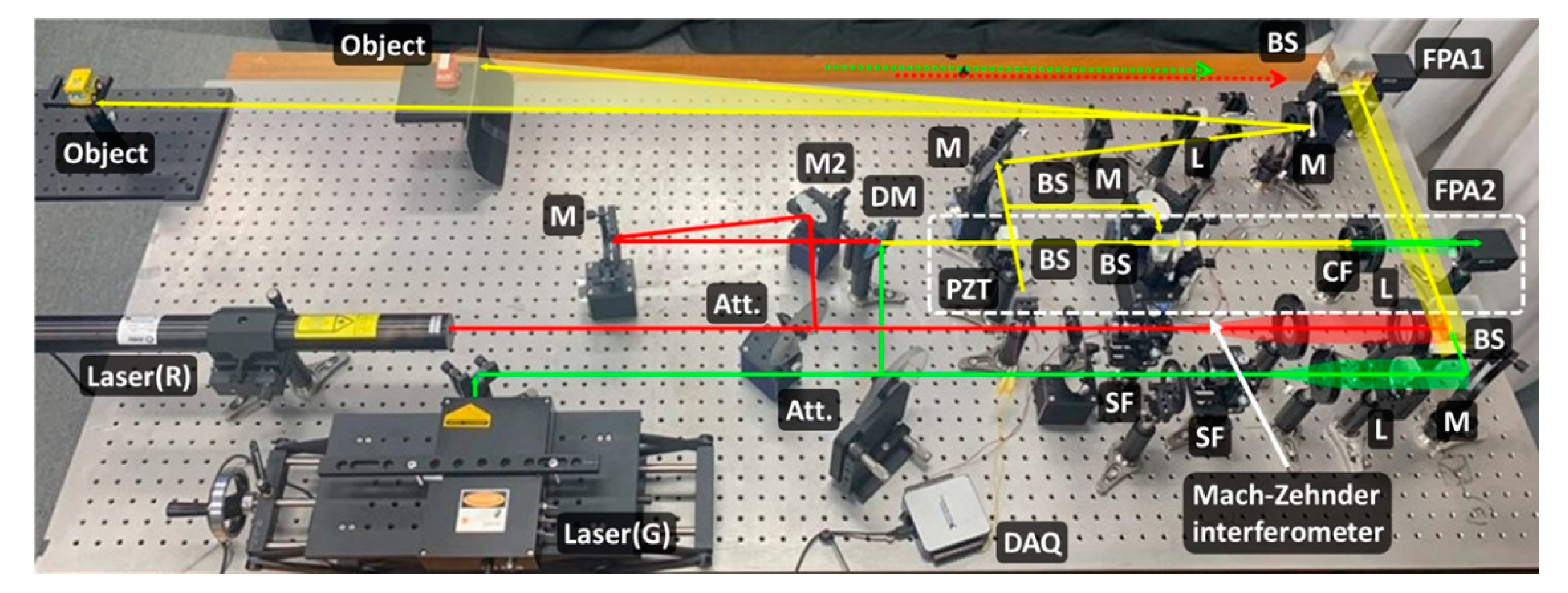
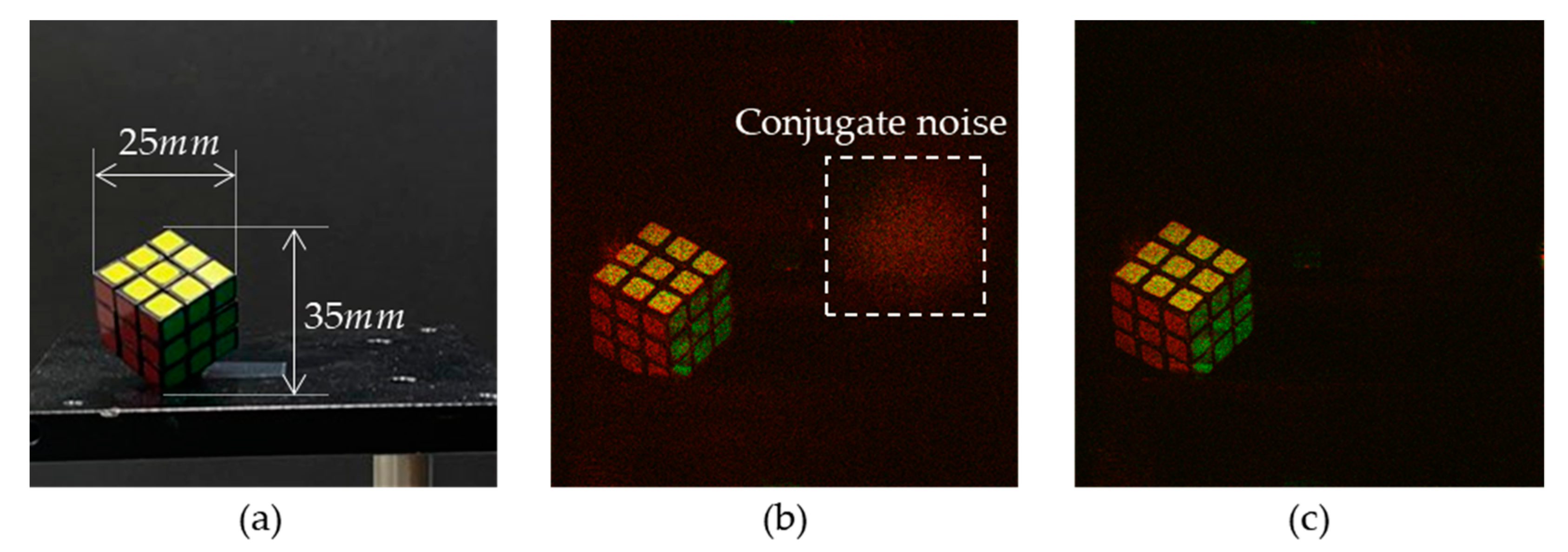
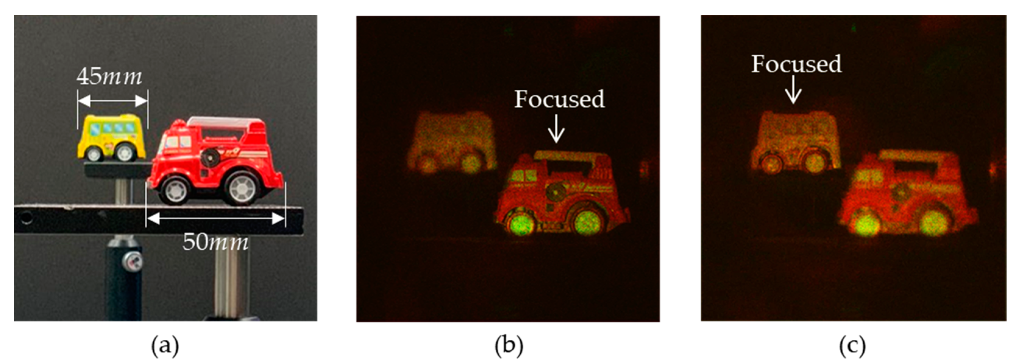
4. Experimental Results

In order to verify our proposed method, we implement a phase-shifting DH with the Mach–Zehnder interferometer inserted as shown in Figure 5. In our system, a laser diode with a 532 nm wavelength and a He-Ne laser with a 633 nm wavelength are used as the light sources. For measuring the color interferogram, Grasshopper GS3-U3-41S4C-C manufactured by Point Grey is used. It has 2016 × 2016 pixels and its pixel pitch is 3.1 µm. For monitoring the phase-shift, Grasshopper GS3-U3-41S6C-C is used. It has 2048 × 2048 pixels and pixel pitch is 5.5 µm. The PZT stack actuator of PI is used as a phase-shifter.
In the first experiment, we make sure that color holography based on the generalized phase-shift algorithm is feasible by numerical reconstruction with negligible conjugate noise. For this purpose, an object, a Rubik’s cube, is placed off the optical axis at 1250 mm away from FPA1. Then, the signal wave reflected from the object is reconstructed numerically on one half side. On the other hand, the conjugate noise may appear on the other half side if the signal wave is reconstructed with the wrong phase-shift values. When the PZT actuator is electrically driven, the shifts are not kept constant even at the same driving voltage. Table 1 presents the monitored phase-shifts according to the driving voltage of the PZT actuator. In our experiment, the PZT actuator is not operated in a close-loop and the system is somewhat sensitive to the vibration. The ratio of actual phase-shift to the targeted value is monitored to fluctuate within about 16 %. The phase-shift of the first step is set to zero without loss of generality. Here, from the phase-shift of the wavelength 532 nm, the phase-shift of the wavelength 633 nm is computed by Equation (6).
Figure 6 shows the object for the first experiment and numerical reconstruction images. The reconstruction image in Figure 6b is computed with four targeted phase-shift values having a π / 2 interval. Since these values are different from the actual values, the conjugate noise appears strongly. On the other hand, the conjugate noise becomes negligible in Figure 6c when the object image is retrieved with the monitored phase-shift values listed in Table 1.
In the second experiment, two objects are located at different distances where red and yellow cars are placed 1250 mm and 1750 mm apart from FPA1, respectively. Here, one object is placed on the opposite half where the other object is placed. So, the bandwidth of the signal occupies almost the entire bandwidth of FPA1. Table 2 lists the monitored phase-shift values according to the driving voltage of the PZT actuator. Figure 7 shows two objects for the second experiment and numerical reconstruction images. Since two objects are positioned at different distances, the yellow car looks out of focus when the red car is focused as shown in Figure 7b. On the other hand, the red car becomes out of focus when the yellow car is focused as shown in Figure 7c. Two objects are reconstructed clearly at the expected depths, respectively. In addition, it is obvious that the conjugate noise of the signal of one object is small enough not to affect the signal of the other. Therefore, we confirm the validity of the proposed algorithm successfully.

5. Discussion

In this paper, we choose the method to acquire the color hologram using an FPA with a Bayer pattern instead of an alternative method using a conventional pixelated-polarizer FPA. In this alternative method, four different micro-polarizers are attached to a monochromatic FPA, and four-step phase-shift interferograms are captured by a single shot. Then the color of the light source is changed sequentially to obtain a color hologram. However, this method has some limitation in measuring the high spatial frequency since the sampling positions correspondent to phase-shifts are different from each other. The interferograms are displaced by a pixel pitch according to the phase-shift. On the other hand, our method has an advantage to obtain the hologram with the full spatial bandwidth.
In this paper, we use an FPA with a Bayer pattern as shown in Figure 2b and only one green color pixel is used in a unit Bayer color pattern to make the sampling intervals of the interferograms in red and green wavelengths to be the same. In this case, the size of the reconstruction domain in the green wavelength is smaller than that in the red wavelength as shown in Figure 3. If we use all green pixels of the Bayer pattern, the reconstruction domain will be enlarged as shown in Figure 8. Since the green pixels are positioned in the diagonal of the unit Bayer pattern, the sampling interval of the green pixels is not 2 p but 2 p in the diagonal direction. Therefore, the green reconstruction domain becomes a square rotated 45 degrees as shown in Figure 8b. Figure 8c shows the overlapped area from the green and red reconstruction. As a result, its shape is a truncated square.

6. Conclusions

In this paper, we present a new method of color phase-shifting DH with monitoring phase-shift. The four-step phase-shift is performed sequentially and interferograms in color are measured simultaneously by using a color filter array. Even though our method is suitable for real-time measurements, we expect that it will be useful for applications requiring high measurement accuracy since our method has the advantage of obtaining holograms over the full bandwidth of spatial frequencies. The proposed method is embodied with the combination of two interferometers. One interferometer is used for measuring the signal wave of objects. In this interferometer, the FPA sensor measures the signal waves for two wavelengths simultaneously with the help of the Bayer color filter. So, we obtain color holograms with only four steps. The other is the Mach–Zehnder interferometer for monitoring actual phase-shift values that are computed from the movement of the fringe pattern due to the PZT actuator. Usually, the actual phase-shift values are different from the expected values because of the instability or hysteresis of the phase shifter. In order to obtain a color signal wave from interferograms with measured phase-shift values, we devise a generalized phase-shifting DH algorithm that is applicable to the case of an arbitrary phase-shift. To verify the feasibility of the proposed method, we demonstrate the proposed algorithm experimentally to reconstruct the object image with negligibly small conjugate noises. In the future, we plan to realize a color phase-shifting DH system with only one FPA for both measuring color interferograms and monitoring phase-shift simultaneously.

Author Contributions

Conceptualization, M.J.; Data curation, H.J.; Formal analysis, S.L.; Investigation, M.J.; Methodology, S.L.; Software, H.J.; Supervision, J.H.; Writing—original draft, M.J.; Writing—review and editing, H.J., S.L., and J.H. All authors have read and agreed to the published version of the manuscript.

Funding

This research was funded by Kyungpook National University Development Project Research Fund, 2018.

Institutional Review Board Statement

Not applicable.

Informed Consent Statement

Not applicable.

Acknowledgments

This research was supported by Kyungpook National University Development Project Research Fund, 2018.

Conflicts of Interest

The authors declare no conflict of interest.

References

  1. Desse, J.M.; Picart, P. Digital color holography for analyzing unsteady wake flows. In New Techniques in Digital Holography; Picart, P., Ed.; John Wiley & Sons, Ltd.: Hoboken, NJ, USA, 2015; pp. 107–136. [Google Scholar]
  2. Kozacki, T.; Chlipala, M.; Makowski, P.L. Color Fourier orthoscopic holography with laser capture and an LED display. Opt. Express 2018, 26, 12144–12158. [Google Scholar] [CrossRef]
  3. Hu, Y.; Luo, X.; Chen, Y.; Liu, Q.; Li, X.; Wang, Y.; Liu, N.; Duan, H. 3D-Integrated metasurfaces for full-color holography. Light Sci. Appl. 2019, 8, 1–9. [Google Scholar] [CrossRef]
  4. Javidi, B.; Moon, I.; Yeom, S.; Carapezza, E. Three-dimensional imaging and recognition of microorganism using single-exposure on-line (SEOL) digital holography. Opt. Express 2005, 13, 4492–4506. [Google Scholar] [CrossRef]
  5. Zakrisson, J.; Schedin, S.; Andersson, M. Cell shape identification using digital holographic microscopy. Appl. Opt. 2015, 54, 7442–7448. [Google Scholar] [CrossRef] [Green Version]
  6. Han, J.-H.; Li, R.-P.; Liu, J.-H.; Hai, F.-S.; Huang, M.-J. Two-step phase shifting differential-recording digital holographic microscopy. Sci. Rep. 2017, 7, 1–8. [Google Scholar] [CrossRef] [Green Version]
  7. Kim, M.K. Full color natural light holographic camera. Opt. Express 2013, 21, 9636–9642. [Google Scholar] [CrossRef]
  8. Javidi, B.; Tajahuerce, E. Three-dimensional object recognition by use of digital holography. Opt. Lett. 2000, 25, 610–612. [Google Scholar] [CrossRef] [PubMed]
  9. Schnars, U.; Jüptner, W.P. Digital recording and numerical reconstruction of holograms. Meas. Sci. Technol. 2002, 13, R85. [Google Scholar] [CrossRef]
  10. Yamaguchi, I.; Zhang, T. Phase-shifting digital holography. Opt. Lett. 1997, 22, 1268–1270. [Google Scholar] [CrossRef] [PubMed]
  11. Yamaguchi, I.; Matsumura, T.; Kato, J.I. Phase-shifting color digital holography. Opt. Lett. 2002, 27, 1108–1110. [Google Scholar] [CrossRef]
  12. Kato, J.I.; Yamaguchi, I.; Matsumura, T. Multicolor digital holography with an achromatic phase shifter. Opt. Lett. 2002, 27, 1403–1405. [Google Scholar] [CrossRef]
  13. Nomura, T.; Shinomura, K. Generalized sequential four-step phase-shifting color digital holography. Appl. Opt. 2017, 56, 6851–6854. [Google Scholar] [CrossRef]
  14. Tahara, T.; Otani, R.; Takaki, Y. Wavelength-selective phase-shifting digital holography: Color three-dimensional imaging ability in relation to bit depth of wavelength-multiplexed holograms. Appl. Sci. 2018, 8, 2410. [Google Scholar] [CrossRef] [Green Version]
  15. Kakue, T.; Tahara, T.; Ito, K.; Shimozato, Y.; Awatsuji, Y.; Nishio, K.; Matoba, O. Parallel phase-shifting color digital holography using two phase shifts. Appl. Opt. 2009, 48, H244–H250. [Google Scholar] [CrossRef] [PubMed]
  16. Han, G.S.; Kim, S.W. Numerical correction of reference phases in phase-shifting interferometry by iterative least squares fitting. Appl. Opt. 1994, 33, 7321–7325. [Google Scholar] [CrossRef] [PubMed]
  17. Schmit, J.; Creath, K. Extended averaging technique for derivation of error-compensating algorithms phase-shifting interferometry. Appl. Opt. 1995, 34, 3610–3619. [Google Scholar] [CrossRef] [PubMed] [Green Version]
  18. Chen, X.; Gramaglia, M.; Yeazell, J.A. Phase-shifting interferometry with uncalibrated phase shifts. Appl. Opt. 2000, 39, 585–591. [Google Scholar] [CrossRef] [PubMed]
  19. Yoshikawa, N.; Shiratori, T.; Kajihara, K. Robust phase-shift estimation method for statistical generalized phase-shifting digital holography. Opt. Express 2014, 22, 14155–14165. [Google Scholar] [CrossRef]
  20. Cai, L.Z.; Liu, Q.; Yang, X.L. Generalized phase-shifting interferometry with arbitrary unknown phase steps for diffraction objects. Opt. Lett. 2004, 29, 183–185. [Google Scholar] [CrossRef] [PubMed]
  21. Cai, L.Z.; Liu, Q.; Yang, X.L. Phase-shift extraction and wave-front reconstruction in phase-shifting interferometry with arbitrary phase steps. Opt. Lett. 2003, 28, 1808–1810. [Google Scholar] [CrossRef] [PubMed]
  22. Hahn, J.; Kim, H.; Cho, S.W.; Lee, B. Phase-shifting interferometry with genetic algorithm-based twin image noise elimination. Appl. Opt. 2008, 47, 4068–4076. [Google Scholar] [CrossRef] [PubMed]
  23. Lim, S.; Choi, K.; Hahn, J.; Marks, D.L.; Brady, D.J. Image-based registration for synthetic aperture holography. Opt. Express 2011, 19, 11716–11731. [Google Scholar] [CrossRef] [PubMed]
  24. Xia, P.; Wang, Q.; Ri, S.; Tsuda, H. Calibrated phase-shifting digital holographic microscope using a sampling moiré technique. Appl. Sci. 2018, 8, 706. [Google Scholar] [CrossRef] [Green Version]
  25. Hahn, J.; Kim, H.; Lee, B. Optimization of the spatial light modulation with twisted nematic liquid crystals by a genetic algorithm. Appl. Opt. 2008, 47, D87–D95. [Google Scholar] [CrossRef] [PubMed]
  26. Hahn, J.; Kim, H. Uncertainty-managed phase-shifting digital holography. Opt. Lett. 2012, 37, 4492–4494. [Google Scholar] [CrossRef]
Figure 1. Scheme of the proposed color phase-shifting holographic system (Att.: Attenuator, BS: Beam splitter, SF: Spatial filter, M: Mirror, DM: Dichroic mirror, L: Lens, CF: Color filter, FPA: Focal plane array).
Photonics 08 00241 g001
Figure 2. Color interferogram captured by the FPA1. (a) Raw image, (b) Bayer pattern, (c) green interferogram, and (d) red interferogram.
Photonics 08 00241 g002
Figure 3. Size of object image captured by the FPA1 depending on the wavelength. (a) Geometry of color DH. Numerical reconstructions from color DH with (b) 532 nm and (c) 633 nm.
Photonics 08 00241 g003
Figure 4. Movement of fringe pattern according to the phase-shift. (a) Fringe pattern and (b) vertically averaged intensity.
Photonics 08 00241 g004
Figure 5. Experiment setup of the proposed color DH system with monitoring phase-shift.
Photonics 08 00241 g005
Figure 6. Object for the first experiment and numerical reconstruction images. (a) Photograph of the object. Numerical reconstruction images (b) without and (c) with monitoring phase-shift.
Photonics 08 00241 g006
Figure 7. Objects for the second experiment and numerical reconstruction images. (a) Photograph of the object. Numerical reconstruction images focused on (b) the near object and (c) the far object.
Photonics 08 00241 g007
Figure 8. Reconstruction domain by the FPA with a Bayer pattern. (a) Bayer pattern and (b) size of reconstruction domain depending on wavelength and sampling interval. (c) Color reconstruction domain is enlarged by using all green pixels of the Bayer pattern.
Photonics 08 00241 g008
Table 1. Driving voltages of the PZT actuator and monitored phase-shifts in the first experiment.
Step1st2nd3rd4th
Driving Voltage (V)1.73.45.16.8
532 nm (rad)00.5639π1.1617π1.7156π
633 nm (rad)00.4739π0.9763π1.4418π
Table 2. Driving voltages of PZT actuator and monitored phase-shifts in the second experiment.
Step1st2nd3rd4th
Driving Voltage (V)1.753.55.257
532 nm (rad)00.5895π1.1680π1.7376π
633 nm (rad)00.4954π0.9816π1.4604π
Publisher’s Note: MDPI stays neutral with regard to jurisdictional claims in published maps and institutional affiliations.

