Article

Performance Analysis of Dual-Hop Mixed Power Line Communication/Free-Space Optical Cooperative Systems

Department of Electrical, Electronic and Computer Engineering, University of Ulsan, Ulsan 44610, Korea
*
Author to whom correspondence should be addressed.
These authors contributed equally to this work.
Photonics 2021, 8(6), 230; https://doi.org/10.3390/photonics8060230
Submission received: 10 May 2021 / Revised: 17 June 2021 / Accepted: 18 June 2021 / Published: 21 June 2021
(This article belongs to the Special Issue Optical Wireless Communications Systems)

Abstract

:
In this paper, we study a mixed cooperative communication system consisting of power line communication (PLC) and free-space optical communication (FSO) links, where the PLC link suffers from log-normal fading and is affected by both impulsive and background noises. Meanwhile, the FSO link undergoes Gamma-Gamma fading with both atmospheric turbulence and pointing errors. More specifically, we present closed-form expressions for the probability density function and the cumulative distribution function of the end-to-end signal-to-noise ratio of the proposed model. Consequently, the outage probability and the bit error rate (BER) performance are derived in terms of univariate Fox-H and bivariate Fox-H functions. Finally, the analytical results are verified using Monte Carlo simulations, providing useful insights into the capabilities of the proposed system.

1. Introduction

Free-space optical (FSO) communication systems with high data rates, high security, and robustness to electromagnetic interference have gained much attention as a promising candidate to overcome the spectrum scarcity in wireless communications systems [1,2]. Nevertheless, the FSO link performance can deteriorate due to atmospheric turbulence, leading to the degradation of the intensity and phase of the estimated optical signal [3,4]. Under various statistical channel models for the FSO channel, a variety of important system performance characteristics such as the outage probability, ergodic capacity, and bit error rate (BER) have been analyzed in recent studies.
On the other hand, power line communication (PLC) has been usually regarded as a low-cost and energy-saving communication technology since it utilizes the existing cables for data transmission [5]. Compared with other methods of communication, PLC has the characteristics of wide coverage, convenient connection, and no need to be rewired, which enables it to be used in both indoor and outdoor communication. However, due to the variations in location and time, it is a challenge to model PLC channels. Furthermore, the random fluctuation of attenuation, noise, and channel impedance in PLC systems makes it very hard to analyze the PLC channel [6].
In the literature, various communication systems have considered integrating either PLC or FSO into either outdoor or indoor broadcasting communication. In [6], the performance of a mixed cooperative communication system between PLC and visible light communication [7,8] was evaluated, while a dual hop wireless-PLC mixed cooperative system. Furthermore, a mixed FSO-radio frequency relaying (RF) system was considered in [9] by using decoding and forwarding (DF) technique. Also, the authors of [10] focused on the impact of pointing error on the performance of a dual-hop relay transmission system composed of asymmetric RF/FSO links and provided exact closed-form expressions for a variety of system key performance metrics. On the other hand, many practical scenarios can benefit from the integration of PLC with FSO using relaying techniques. To transmit information signals from an indoor source to an outdoor destination using an FSO link, there are various solutions such as implementing fiber optic or Wi-Fi signal links [11]. With the former approach, the cost of implementation and maintenance can be high in some scenarios, while in the latter option, due to the presence of large obstacles and dead zones the signal fluctuations are a hindrance. However, currently, no research focuses on the cooperative transmission of the PLC-FSO relaying system. With its advantages such as cost-efficient and high rate communication, the combined deployment of the readily available PLC infrastructure with the FSO link has potential practical implementations and thus warrants investigation.
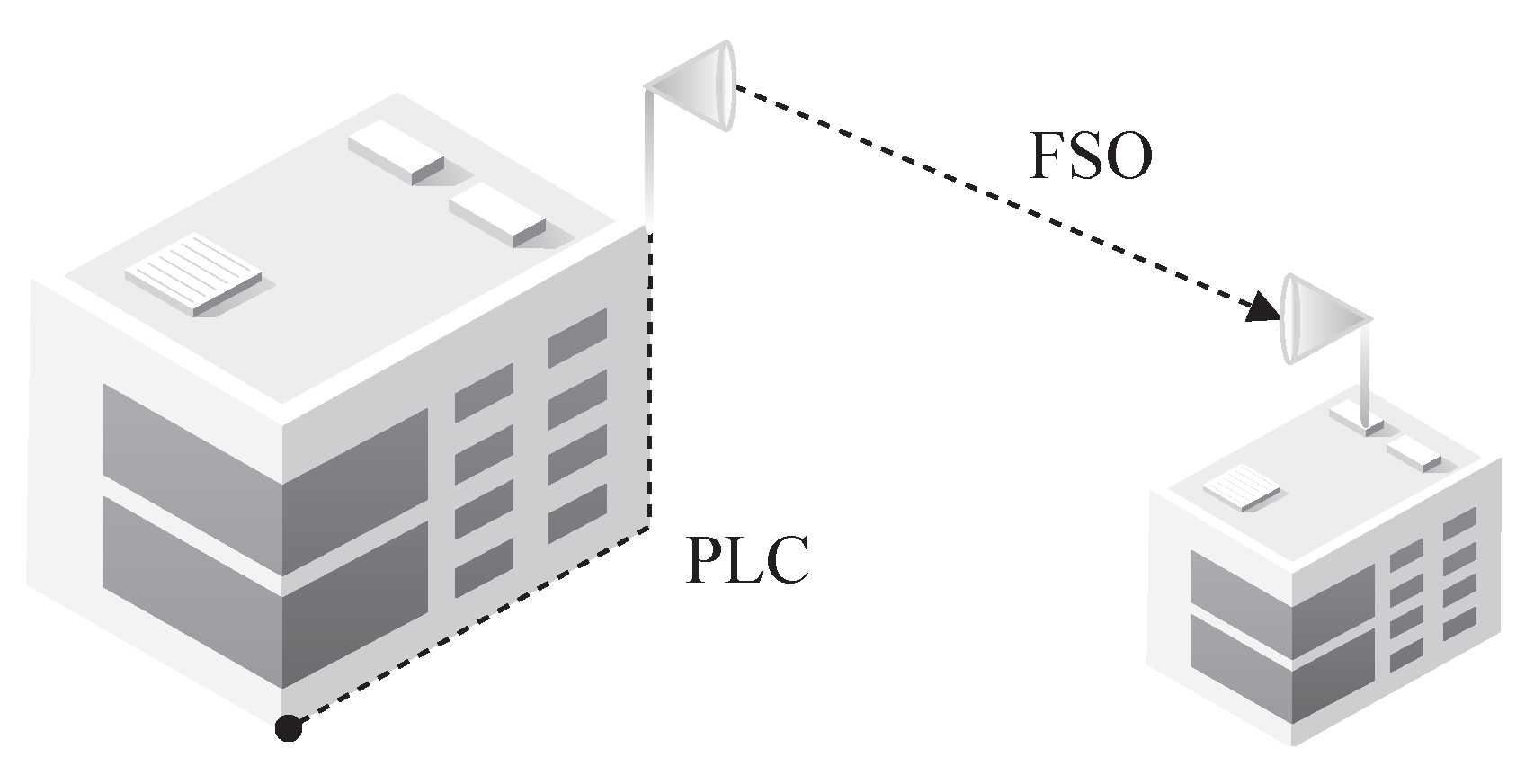
In this paper, due to the potential for simple implementations and high energy efficiency, we consider DF relaying systems that combine PLC and FSO integration. The proposed mixed system can support wireless networks to reach remote geographical area through the ubiquitous indoor power line infrastructure. More specifically, the analytical results are provided considering the effects of both pointing errors and various types of turbulence in the FSO link, as well as the impulsive-background noise in the PLC link. We derive the probability density function (PDF) and the cumulative distribution function (CDF) for the end-to-end SNR of the proposed system. Consequently, in compilation with the Gamma-Gamma distribution of the FSO link, the log-normal distribution of the PLC link is approximated using a Gamma distribution, thereby obtaining a tractable closed-form expression of the analytical BER performance and the outage probability of the proposed system. The results demonstrate that the analytical derivation exactly matched with the Monte-Carlo simulations, providing insights into the proposed system under various channel conditions.
The remainder of this paper is organized as follows. In Section 2, we present the descriptions of the communication system and the channel model, include the PLC and FSO channel models. In Section 3, we provide the derivation the CDF and PDF of the end-to-end SNR of proposed system. The mathematical expressions of the outage probability, the average BER, in Section 4. The diversity order of the proposed system is presented in Section 5 using asymptotic analysis at high SNR regime based on the derived outage probability. Consequently, some simulation results using Monte-Carlo simulation are presented in Section 6 to validate the mathematical correctness of the derived mathematical results. Finally, some concluding remarks are provided in Section 6.

2. Proposed System Model

In Figure 1, we consider a cooperative transmission from a source node to a destination node through a relay node, which uses DF relaying to decode and encode the received signal, then retransmits the data to the next destination. The communication link from the source to the relay is PLC, while FSO communication is used for the link from the relay to the destination. Furthermore, it is assumed that the relay node is equipped with the capability to interface between the PLC and FSO link.

2.1. Plc Channel Model

From the source node, the power cables carry the information data to the FSO link with the assistance of a DF relay. Along the power lines, the channel gain of the PLC link is subjected to a log-normal distribution [6] with Bernoulli-Gaussian noise as the signal passes through reflections, impedance mismatches, and impulsive noise. More specifically, the PDF of these coefficients is given as
f H 1 h 1 = 1 h 1 2 π σ 1 2 exp ln h 1 μ 1 2 2 σ 1 2 ,
where h 1 > 0 , μ 1 and σ 1 2 are the mean and the variance of ln h 1 , respectively. Moreover, the PLC link suffers from both impulsive noise and background noise due to various switching transients, low-power noise sources, and the cables [6]. The instantaneous SNR value on the PLC link is γ 1 = γ ¯ 1 , 1 h 1 2 when no impulsive noise occurs. The SNR value is γ 1 = γ ¯ 1 , 2 h 1 2 in the presence of both impulsive noise and background noise where the average SNR are γ ¯ 1 , 1 = E b σ G 2 and γ ¯ 1 , 2 = E b σ I 2 + σ G 2 , respectively. Beside, E b denotes the average energy of the signal. Since the channel coefficient of the PLC link is log-normally distributed, the corresponding PDF of γ 1 is also log-normally distributed. Assuming that ρ is the arrival probability of the impulsive noise, the PDF of the instantaneous SNR γ 1 at the PLC link can be represented as
f γ 1 ( γ ) = 1 ρ 1 2 π σ u 2 γ exp ln γ μ u 2 2 σ u 2 + ρ 1 2 π σ v 2 γ exp ln γ μ v 2 2 σ v 2 ,
where μ u = 2 μ 1 + ln γ ¯ 1 , 1 , σ u = 4 σ 1 2 , μ v = 2 μ 1 + ln γ ¯ 1 , 2 , and σ v = 4 σ 1 2 . Consequently, the log-normally distributed PDF of γ 1 can be approximated with the Gamma distribution as
f γ 1 ( γ ) = Δ 1 φ Φ φ γ φ 1 exp γ φ Φ + Δ 2 φ Φ φ γ φ 1 exp γ φ Φ ,
where Δ 1 = 1 ρ Γ φ and Δ 2 = ρ Γ φ . Here, φ = e σ u 2 1 1 and φ = e σ v 2 1 1 represent the shadowing parameters while Φ = e μ u 1 + φ φ 1 / 2 and Φ = e μ v 1 + φ φ 1 / 2 are the shadowing area mean power of the Gamma distribution [12].

2.2. Fso Channel Model

The FSO channel gain is modeled as H 2 = h l h a h p , where h l , h a , and h p are the deterministic propagation loss, the atmospheric turbulence incurred attenuation, and the pointing error incurred attenuation, respectively. More specifically, the heat from the sun causes atmospheric turbulence and scintillation to the FSO link [4,10]. Moreover, the atmospheric turbulence-induced fading is dominant factor that significantly impacts the performance of the transmission when the weather condition is good. On the other hand, the pointing error caused by misalignment between transmitter and receiver on physical impacted transmitter beam [6,10]. Therefore, significant performance degradation is expected due to severe atmospheric turbulence and pointing error condition in many scenarios such as urban areas, where the FSO transceivers are placed on high-rise buildings. Moreover, the PDF of the instantaneous SNR of the FSO communication link [9], γ 2 , can be given by
f γ 2 ( γ ) = α β Ω γ H 1 , 3 3 , 0 γ ψ | ξ 2 + 1 , r ξ 2 , r ( α , r ) ( β , r ) ,
where H p , q m , n · is the Fox H-function and Γ · is the Gamma function. In (4), Ω = ξ 2 Γ α Γ β , ψ = γ ¯ 2 α β r , r = 1 represents heterodyne detection, and r = 2 represents direct detection. If σ s denotes the standard deviation of the pointing error distribution, the equivalent beam-width [4] can be expressed as ξ = w e / 2 σ s , where w e is the equivalent beam radius at the receiver. Furthermore, γ ¯ 2 denotes the average electrical SNR of the FSO link [3], which can be defined as γ ¯ 2 = γ ¯ FSO for r = 1 and for r = 2 we have
γ ¯ 2 = γ ¯ FSO α β ξ 2 ξ 2 + 1 ( α + 1 ) ( β + 1 ) ξ 2 + 1 2 ,
where the average SNR is γ ¯ FSO = E [ γ ] and E is the expectation operator. The fading parameter α is the effective number of large-scale cells and β is the effective number of small-scale cells of the atmospheric conditions in the scattering process [13].

3. Statistics of the Snr of Equivalent End-to-End Communication Link

3.1. Cumulative Distribution Function

Using the DF relaying protocol, the CDF of the end-to-end SNR for the proposed system can be expressed as [9]
F γ e ( γ ) = Pr min γ 1 , γ 2 < γ .
By substituting (3) into F γ ( γ ) = 0 γ f γ ( γ ) d γ , the CDF of γ 1 can be expressed as
Pr γ 1 < γ = Δ 1 φ Φ φ 0 γ γ φ 1 exp γ φ Φ d γ + Δ 2 φ Φ φ 0 γ γ φ 1 exp γ φ Φ d γ .
Using Equation (8.4.16) from [14] and after some simple manipulations, the CDF of γ 1 can be written as
Pr γ 1 < γ = Δ 1 × H 1 , 2 1 , 1 φ γ Φ φ , 1 0 , 1 1 , 1 + Δ 2 × H 1 , 2 1 , 1 φ γ Φ φ , 1 0 , 1 1 , 1 .
Similarly, by substituting (4) into F γ ( γ ) = 0 γ f γ ( γ ) d γ and using Equation (2.4.5) from [15], the CDF of γ 2 can be expressed as
Pr γ 2 < γ = 1 Ω × H 2 , 4 4 , 0 γ ψ | 1 , r ξ 2 + 1 , r ξ 2 , r α , r β , r 0 , r .
Furthermore, we assume that PLC and FSO links are independent. Hence, the CDF of end-to-end SNR can be further expressed as
F γ e ( γ ) = Pr γ 1 < γ + Pr γ 2 < γ Pr γ 1 < γ Pr γ 2 < γ = 1 + Ω × H 2 , 4 4 , 0 γ ψ | 1 , r ξ 2 + 1 , r ξ 2 , r α , r β , r 0 , r × 1 Δ 1 × H 1 , 2 1 , 1 φ γ Φ φ , 1 0 , 1 1 , 1 Δ 2 × H 1 , 2 1 , 1 φ γ Φ φ , 1 0 , 1 1 , 1 .

3.2. Probability Density Function

The closed-form analytic expression of the PDF of the end-to-end SNR can be derived by differentiating (10) w.r.t. γ . Using ([16], Equation (1.69)), f γ e γ can be given as
f γ e γ = Ω r × 1 γ H 1 , 3 3 , 0 α β Y 1 r γ | ξ 2 + 1 , r ξ 2 , r α , r β , r × 1 Δ 1 × H 1 , 2 1 , 1 φ γ Φ φ , 1 0 , 1 1 , 1 Δ 1 × H 1 , 2 1 , 1 φ γ Φ φ , 1 0 , 1 1 , 1 + Ω r × H 2 , 4 4 , 0 γ ψ | 1 , r ξ 2 + 1 , r ξ 2 , r α , r β , r 0 , r × Δ 1 γ H 2 , 3 1 , 2 φ Φ γ φ , 1 0 , 1 1 , 1 0 , 1 1 , 1 + Δ 2 γ H 2 , 3 1 , 2 φ Φ γ φ , 1 0 , 1 1 , 1 0 , 1 1 , 1 .

4. Performance Evaluation of Mixed Plc-Fso System

4.1. Outage Probability Analysis

The outage probability can be defined as the probability that the end-to-end SNR γ e , has a value smaller than a certain specified threshold, γ t h . It is well-known that when the instantaneous SNR γ e < γ t h , the communication system undergoes the outage state, in which the received SNR γ e can not support the target rate of the system. For the proposed mixed PLC-FSO system with DF relaying, an exact closed-form analytic expression for the outage probability can be represented as [4]
P out γ t h = Pr γ e < γ t h = F γ e γ t h .

4.2. Bit Error Rate Analysis

For a variety of binary and non-binary modulation schemes, a unified expression of the BER is given as in [1,6,9]
P ¯ b = δ 2 Γ ( p ) k = 1 n q k p 0 γ p 1 e q k γ F γ e ( γ ) d γ = δ n 2 δ 2 Γ ( p ) k = 1 n Ω I 1 Δ 1 Ω I 2 Δ 2 Ω I 3 ,
where n , δ , p , and q k are used to denote the parameters for different modulation schemes, as defined in [1,6,9]. Furthermore, we have terms I 1 , I 2 , and I 3 which can be expressed as
I 1 = q k p 0 γ p 1 e q k γ H 2 , 4 4 , 0 t ψ | 1 , r ξ 2 + 1 , r ξ 2 , r α , r β , r 0 , r d t ,
I 2 = q k p 0 γ p 1 e q k γ H 1 , 2 1 , 1 φ t Φ m , 1 0 , 1 1 , 1 × H 2 , 4 4 , 0 t ψ | 1 , r ξ 2 + 1 , r ξ 2 , r α , r β , r 0 , r d t ,
I 3 = q k p 0 γ p 1 e q k γ H 1 , 2 1 , 1 φ t Φ m i , 1 0 , 1 1 , 1 × H 2 , 4 4 , 0 t ψ | 1 , r ξ 2 + 1 , r ξ 2 , r α , r β , r 0 , r d t .
Then, by expanding the Fox H-function ([16], Equation (1.2)), we have I 1 as
I 1 = q k p 2 π j 0 C Γ ξ 2 + r s Γ α + r s Γ β + r s Γ 0 + r s Γ 1 + r s Γ 1 + ξ 2 + r s t ψ s t p 1 e q k t d s d t
By integrating (17) w.r.t. t and using the definition of the univariate Fox-H function ([16], Equation (A.1)), we have I 1 that can be expressed as
I 1 = 1 2 π j C Γ ξ 2 + r s Γ α + r s Γ β + r s Γ 0 + r s Γ p s Γ 1 + r s Γ 1 + ξ 2 + r s 1 q k ψ s d s = H 3 , 4 4 , 1 1 q k ψ | 1 p , 1 , 1 , r ξ 2 + 1 , r ξ 2 , r α , r β , r 0 , r .
Furthermore, by expanding the Fox-H function ([16], Equation (1.2)), we have I 2 as
I 2 = 1 4 π 2 0 C 1 C 2 Γ m + s 1 Γ 1 1 s 1 Γ ξ 2 + r s 2 Γ α + r s 2 Γ β + r s 2 Γ 0 + r s 2 Γ 0 + s 1 Γ 1 + r s 2 Γ 1 + ξ 2 + r s 2 × φ t Φ s 1 t ψ s 2 t p 1 e q k t d s 1 d s 2 d t .
Taking the integration (19) by t with the definition of the bivariate Fox-H function ([16], Equation (A.1)), after changing variable s 1 , s 2 s 1 , s 2 , we have I 2 that can be expressed as
I 2 = H 1 , 0 : 1 , 2 : 2 , 4 0 , 1 : 1 , 1 : 4 , 0 φ Φ q k 1 ψ q k | 1 p ; 1 , 1 1 , 1 m , 1 0 , 1 1 , r ξ 2 + 1 , r ξ 2 , r α , r β , r 0 , r ,
where H p , q : p 1 , q 1 : p 2 , q 2 m , n : m 1 , n 1 : m 2 , n 2 · is the bivariate Fox-H function as defined in ([16], Equation (A.1)). Similarly, I 3 is given as
I 3 = H 1 , 0 : 1 , 2 : 2 , 4 0 , 1 : 1 , 1 : 4 , 0 φ Φ q k 1 ψ q k | 1 p ; 1 , 1 1 , 1 m , 1 0 , 1 1 , r ξ 2 + 1 , r ξ 2 , r α , r β , r 0 , r
It should be mentioned that the MATLAB implementation of the Fox-H and bivariate Fox-H function are presented in [17,18], respectively. Consequently, by placing (18), (20), and (21) into (13), the average BER can be expressed as
P ¯ b = δ n 2 δ Ω 2 Γ ( p ) k = 1 n ( H 3 , 4 4 , 1 1 q k ψ | 1 p , 1 , 1 , r ξ 2 + 1 , r ξ 2 , r α , r β , r 0 , r Δ 1 H 1 , 0 : 1 , 2 : 2 , 4 0 , 1 : 1 , 1 : 4 , 0 φ Φ q k 1 ψ q k | 1 p ; 1 , 1 1 , 1 m , 1 0 , 1 1 , r ξ 2 + 1 , r ξ 2 , r α , r β , r 0 , r Δ 2 H 1 , 0 : 1 , 2 : 2 , 4 0 , 1 : 1 , 1 : 4 , 0 φ Φ q k 1 ψ q k | 1 p ; 1 , 1 1 , 1 m , 1 0 , 1 1 , r ξ 2 + 1 , r ξ 2 , r α , r β , r 0 , r ) .

5. Diversity Analysis

Due to the complex expression of the system end-to-end outage probability, the importance and impact of each system parameter is complicate to investigate. Therefore, in this section, we emphasize on the outage probability in high SNR regime to evaluate the diversity order and provide further engineering insights into the overall system performance. More specifically, using ([15], Equations (1.1.1) and (1.5.9)), with the assumption that γ ¯ 1 , 1 , γ ¯ 1 , 2 , γ ¯ 2 , the outage probability can be asymptotically expressed as
P out γ t h 1 + Ω r × [ Γ α ξ 2 Γ β ξ 2 Γ ξ 2 Γ 1 ξ 2 γ ψ ξ 2 r + Γ ξ 2 α Γ β α Γ α Γ 1 α Γ 1 + ξ 2 α γ ψ α r + Γ ξ 2 β Γ α β Γ β Γ 1 β Γ 1 + ξ 2 β γ ψ β / r + Γ ξ 2 Γ α Γ β Γ 1 + ξ 2 ] × 1 Δ 1 × Γ φ Γ 1 + φ φ γ Φ φ Δ 2 × Γ φ Γ 1 + φ φ γ Φ φ .
Consequently, the diversity order of the dual-hop system is defined as
d = lim γ ¯ log P out log ( γ ¯ ) ,
and can be given by
d = min ξ 2 r , α r , β r , φ , φ .

6. Simulation Results

In this section, the numerical results from the Monte Carlo simulations with 10 7 samples are provided to show the validity of the analytical results and provide some insights into how different parameters affect the proposed system performance. More specifically, we show the impacts of various impulsive noise, turbulence conditions, and pointing errors on the performance of the proposed system under two detection techniques, heterodyne and direct detection, which are denoted by r = 1 and r = 2 , respectively. For the FSO link, we set α , β as 4.6 , 7.1 , 2.4 , 4.5 , and 1.4 , 3.5 , corresponding to weak, moderate, and strong turbulence, respectively. Similarly, for the PLC link, the impulsive noise frequency and intensity vary from weak to strong levels in terms of ρ and the ratio σ I 2 / σ G 2 . Also, we have ξ = 1.5 while μ 1 = 0 , σ 1 2 = 0.18 , and φ = φ = 1.55 . The values of n , δ , and q k are (1,1,1) and (1,1,1/2) when BPSK and QPSK modulations are used, respectively. Additionally, in all figures, the theoretical results perfectly match the Monte-Carlo simulation results, demonstrating the accuracy of the analytical derivation.
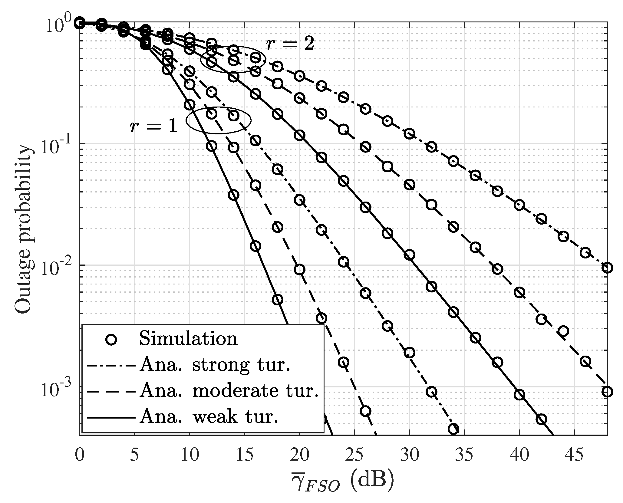
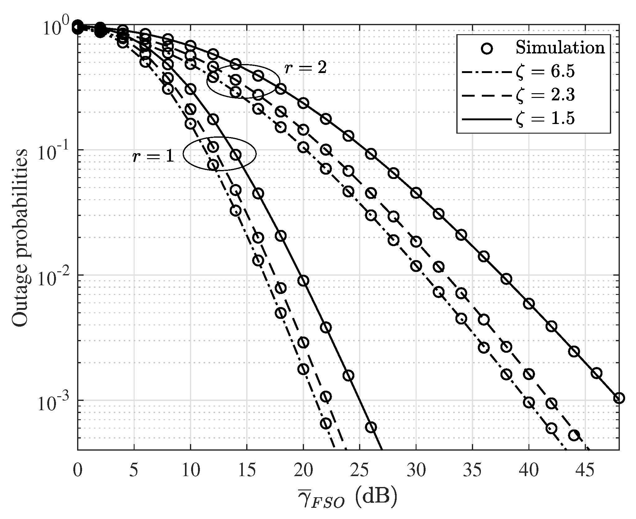
In Figure 2, we show the outage probability versus γ ¯ FSO for both cases of r = 1 and r = 2 under weak, moderate, and strong turbulence conditions. For a fixed average SNR of the PLC link, we can see that the outage probability significantly depends on the parameters of the FSO link. It can be observed that with the direct detection technique, the outage probability of the proposed system is higher than when the heterodyne detection is employed. Additionally, stronger turbulence leads to a higher outage probability.
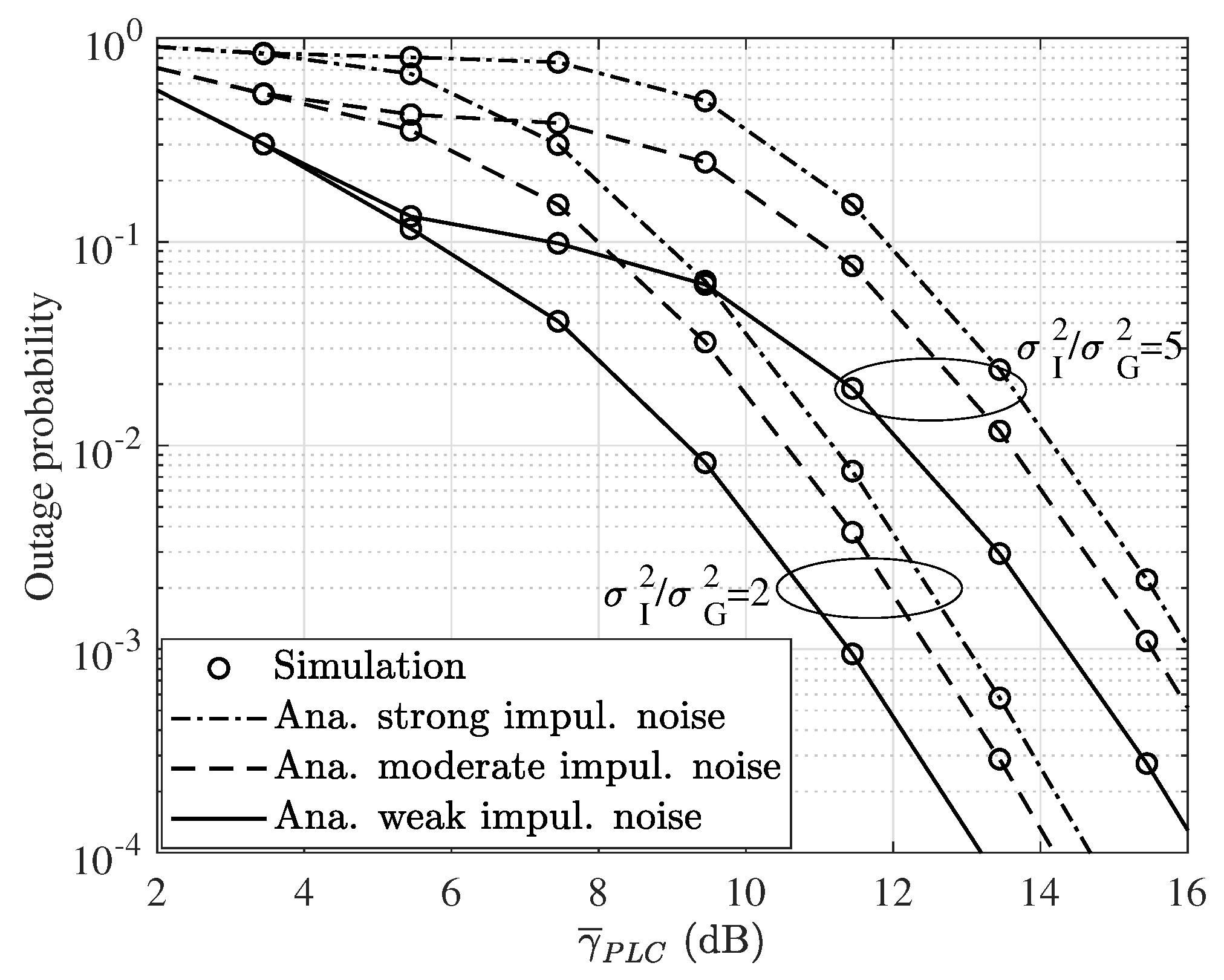
In Figure 3, we show the impacts of various PLC link parameters on the outage probability of the proposed system when the average SNR of the FSO link is fixed at 50 dB. More specifically, three scenarios are considered, where the strong, moderate, and weak impulsive noise conditions are given as ρ = 0.1 , 0.4 , and 0.8 , respectively. The outage probability of the system increases with the stronger impulsive noise level, while weak impulsive noise achieves lower outage probability. On the other hand, the higher the impulsive noise is compared with the background noise, the higher the outage probability is, as σ I 2 / σ G 2 changes from a low value of 0.2 to 0.5.
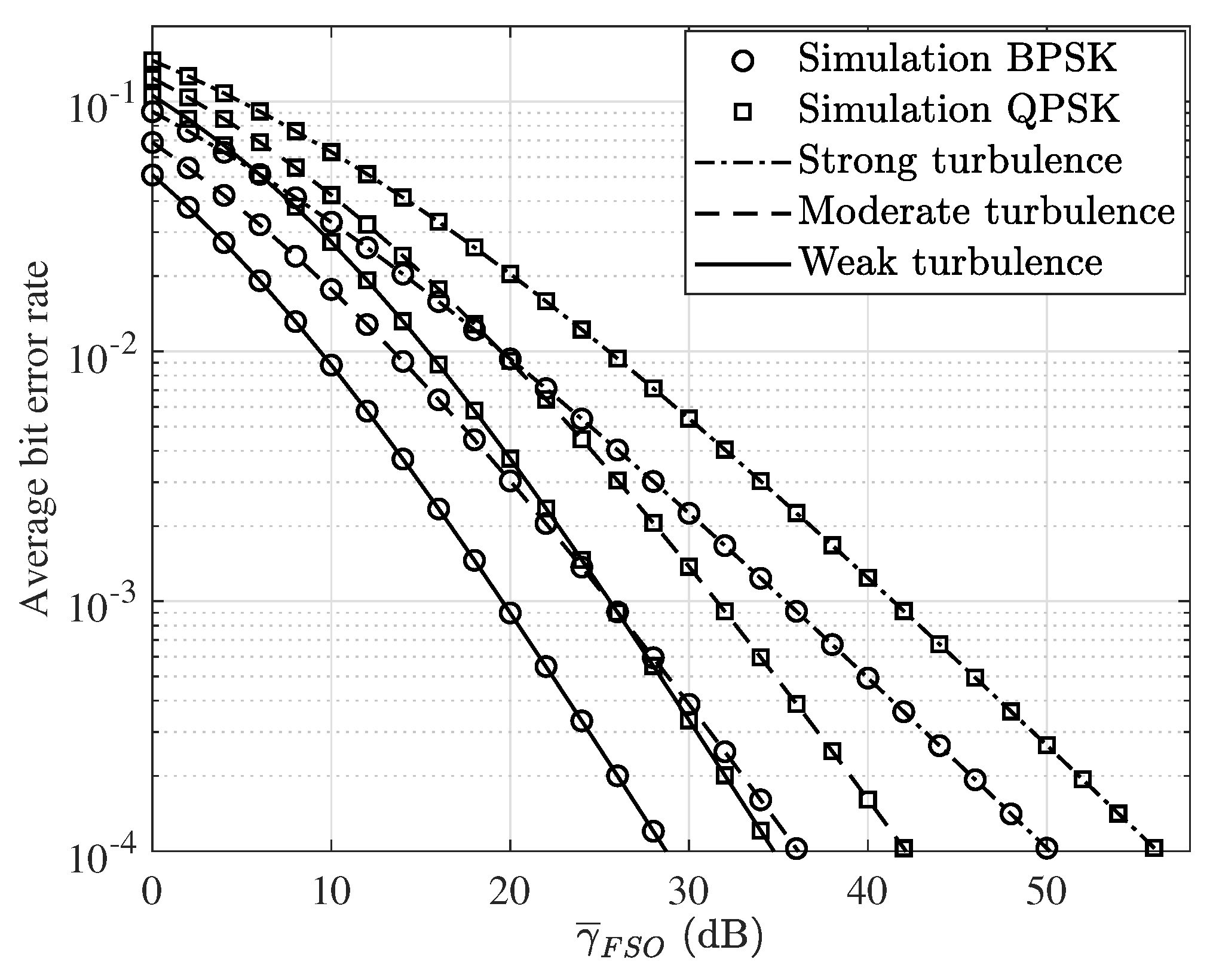
Furthermore, the BER of the proposed system is given in Figure 4 with the average SNR of the FSO link versus different values for the turbulence conditions and two modulation schemes such as quadrature phase-shift keying (QPSK) and binary phase-shift keying (BPSK). It is observed that the average BER performance provides a perfect match to the closed-form expression of our analytical derivation. As expected, the BPSK modulation achieves better performance in comparison with the QPSK modulation. Meanwhile, as the turbulence of the FSO link raises, the BER performance becomes worse.
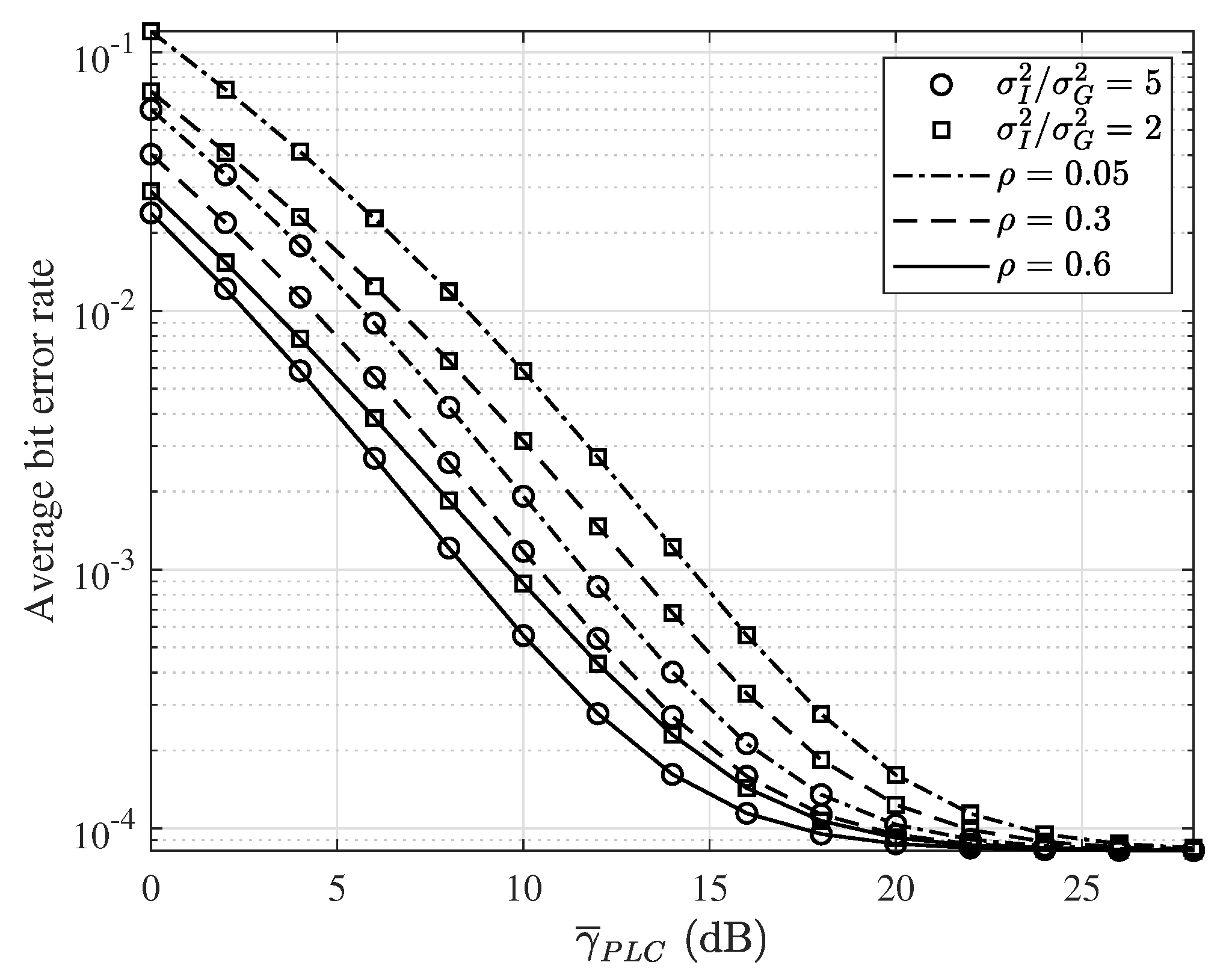
In Figure 5, we present the BER of the proposed system versus the average SNR of the PLC link under various channel conditions, in which the impulsive noise change from weak to strong, described by the values of ρ and σ I 2 / σ G 2 , respectively. Moreover, the average SNR value of the FSO link is fixed at 40 dB while the modulation type is BPSK. From Figure 5, it is clear that both FSO and PLC links have significant impact on the overall performance and an increasing in the quality of individual link can result in an improvement of the BER result. Moreover, high values of impulse noise probability and power of noise lead to higher error probability. Also, the with the fixed SNR value of the FSO link, when the SNR of PLC link approach relatively high values, the FSO link become dominant factor and the BER performance can only achieve a value of 10 4 .
Finally, in Figure 6, the impact of pointing error versus the average SNR of the FSO link is shown in the medium turbulence condition. Also, similar to Figure 2, r = 1 and r = 2 are used to observe the persistence of different detectors on the outage performance for various pointing error conditions. It can be seen that when ζ = 6.5 , the proposed system can achieve the best outage performance while a decrease from ζ = 2.3 to ζ = 1.5 can dramatically degrade the system performance due to severe impact of pointing error at ζ = 1.5 .

7. Conclusions

In this paper, we analyze the performance of a mixed PLC-FSO communication system operating over a turbulence channel in the presence of pointing errors at the FSO link and impulsive-background noise at the PLC link. Under different system parameters, the results demonstrate that the outage probability and BER performance improve as the effects of pointing error, turbulence, or impulsive-background noise decrease. More specifically, results on various system parameters show that severe pointing error and turbulence condition on the FSO link can lead to degradation of the outage probability and average BER performance. Similarly, high values of impulse noise probability and noise power in PLC link also leads to poor performance. Also, the diversity order of the proposed system only depends on the values of α , β , ζ , r , ϕ , and ϕ . Our study also shows that the simulation results coincide with the analytical curves at various SNR values. From the derived analytical results, the performance of proposed system can be thoroughly investigated to show the impact of various critical system parameters. Consequently, from the trends of the simulation and analytical results, the PLC transmission link is shown to be a promising backhaul solution for the FSO link and integration of both PLC and FSO links can provide an efficient indoor to outdoor transmission technique.

Author Contributions

All authors discussed the contents of the manuscript and contributed to its presentation. M.L.-T. designed and implemented the proposed scheme, analyzed the simulation results and wrote the paper under the supervision of S.K. All authors have read and agreed to the published version of the manuscript.

Funding

This work was supported by the Research Program through the National Research Foundation of Korea (NRF-2019R1A2C1005920).

Institutional Review Board Statement

The study did not involve humans or animal studies.

Informed Consent Statement

The study did not involve humans or animal studies.

Data Availability Statement

The study did not report any data.

Conflicts of Interest

The authors declare no conflict of interest.

Abbreviations

The following abbreviations are used in this manuscript:
AWGNAdditive white Gaussian noise
FSOFree-space optical
PLCPower line communication
CDFCumulative distribution function
PDFProbability density function
SNRSignal-to-noise ratio
DFDecode-and-forward
BPSKBinary phase-shift keying
QPSKQuadrature phase-shift keying
BERBit error rate

References

  1. Badarneh, O.S.; Derbas, R.; Almehmadi, F.S.; Bouanani, F.E.; Muhaidat, S. Performance Analysis of FSO Communications over F Turbulence Channels with Pointing Errors. IEEE Commun. Lett. 2021, 25, 926–930. [Google Scholar] [CrossRef]
  2. Garlinska, M.; Pregowska, A.; Gutowska, I.; Osial, M.; Szczepanski, J. Experimental Study of the Free Space Optics Communication System Operating in the 8–12 Mm Spectral Range. Electronics 2021, 10, 875. [Google Scholar] [CrossRef]
  3. Hamza, A.S.; Deogun, J.S.; Alexander, D.R. Classification Framework for Free Space Optical Communication Links and Systems. IEEE Commun. Surv. Tutor. 2018, 21, 1346–1382. [Google Scholar] [CrossRef]
  4. Qin, D.; Wang, Y.; Zhou, T. Performance Analysis of Hybrid Radio Frequency and Free Space Optical Communication Networks with Cooperative Spectrum Sharing. Photonics 2021, 8, 108. [Google Scholar] [CrossRef]
  5. Majumder, A.; J, J.C. Power Line Communications. IEEE Potentials 2004, 23, 4–8. [Google Scholar] [CrossRef]
  6. Jani, M.; Garg, P.; Gupta, A. Performance Analysis of a Mixed Cooperative PLC–VLC System for Indoor Communication Systems. IEEE Syst. J. 2020, 14, 469–476. [Google Scholar] [CrossRef]
  7. Le-Tran, M.; Kim, S. Deep Learning-Based Collaborative Constellation Design for Visible Light Communication. IEEE Commun. Lett. 2020, 24, 2522–2526. [Google Scholar] [CrossRef]
  8. Le-Tran, M.; Kim, S. Deep Learning-Assisted Index Estimator for Generalized LED Index Modulation OFDM in Visible Light Communication. Photonics 2021, 8, 168. [Google Scholar] [CrossRef]
  9. Gupta, A.; Sharma, N.; Garg, P.; Alouini, M. Cascaded FSO-VLC Communication System. IEEE Wirel. Commun. Lett. 2017, 6, 810–813. [Google Scholar] [CrossRef] [Green Version]
  10. Ansari, I.S.; Yilmaz, F.; Alouini, M. Impact of Pointing Errors on the Performance of Mixed RF/FSO Dual-Hop Transmission Systems. IEEE Wirel. Commun. Lett. 2013, 2, 351–354. [Google Scholar] [CrossRef] [Green Version]
  11. Haykin, S.; Moher, M. Communication Systems; Wiley: Hoboken, NJ, USA, 2009. [Google Scholar]
  12. Mathur, A.; Bhatnagar, M.R.; Ai, Y.; Cheffena, M. Performance Analysis of a Dual-Hop Wireless-Power Line Mixed Cooperative System. IEEE Access 2018, 6, 34380–34392. [Google Scholar] [CrossRef]
  13. Dabiri, M.T.; Sadough, S.M.S. Generalized Blind Detection of OOK Modulation for Free-Space Optical Communication. IEEE Commun. Lett. 2017, 21, 2170–2173. [Google Scholar] [CrossRef]
  14. Gradshteĭn, I.S.; Zwillinger, D. Table of Integrals, Series, and Products, 8th ed.; Elsevier: Amsterdam, The Netherlands, 2015. [Google Scholar]
  15. Saigō, M.; Kilbas, A.A. H-Transforms: Theory and Applications; Analytical Methods and Special Functions; Chapman & Hall/CRC: Boca Raton, FL, USA, 2004. [Google Scholar]
  16. Mathai, A.M.; Saxena, R.K.; Haubold, H.J. The H-Function: Theory and Applications; Springer: Berlin/Heidelberg, Germany, 2009. [Google Scholar]
  17. Soulimani, A.; Benjillali, M.; Chergui, H.; da Costa, D.B. On Multihop Weibull-Fading Communications: Performance Analysis Framework and Applications. arXiv 2018, arXiv:1610.08535v3. [Google Scholar]
  18. Chergui, H.; Benjillali, M.; Saoudi, S. Performance Analysis of Project-and-Forward Relaying in Mixed MIMO-Pinhole and Rayleigh Dual-Hop Channel. IEEE Commun. Lett. 2016, 20, 610–613. [Google Scholar] [CrossRef] [Green Version]
Figure 1. System model.
Photonics 08 00230 g001
Figure 2. Outage probability versus γ ¯ FSO with different turbulence conditions and different detection modes.
Photonics 08 00230 g002
Figure 3. Outage probability versus γ ¯ PLC with different impulsive and background noise conditions.
Photonics 08 00230 g003
Figure 4. Average BER performance versus γ ¯ FSO with different turbulence conditions and different modulation schemes using heterodyne detection.
Photonics 08 00230 g004
Figure 5. Average BER performance versus γ ¯ PLC with different impulse noise conditions and γ ¯ FSO = 40 dB.
Photonics 08 00230 g005
Figure 6. Outage probability versus γ ¯ FSO with various pointing error conditions and detection modes.
Photonics 08 00230 g006
Publisher’s Note: MDPI stays neutral with regard to jurisdictional claims in published maps and institutional affiliations.

