Monolithic, Optically Coupled, Multi-Section Mid-IR Quantum Cascade Lasers

 , , , and
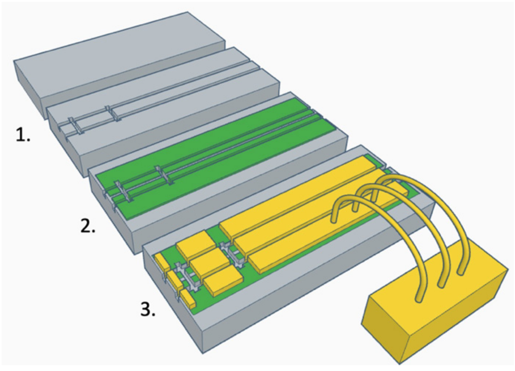
Abstract
:1. Introduction
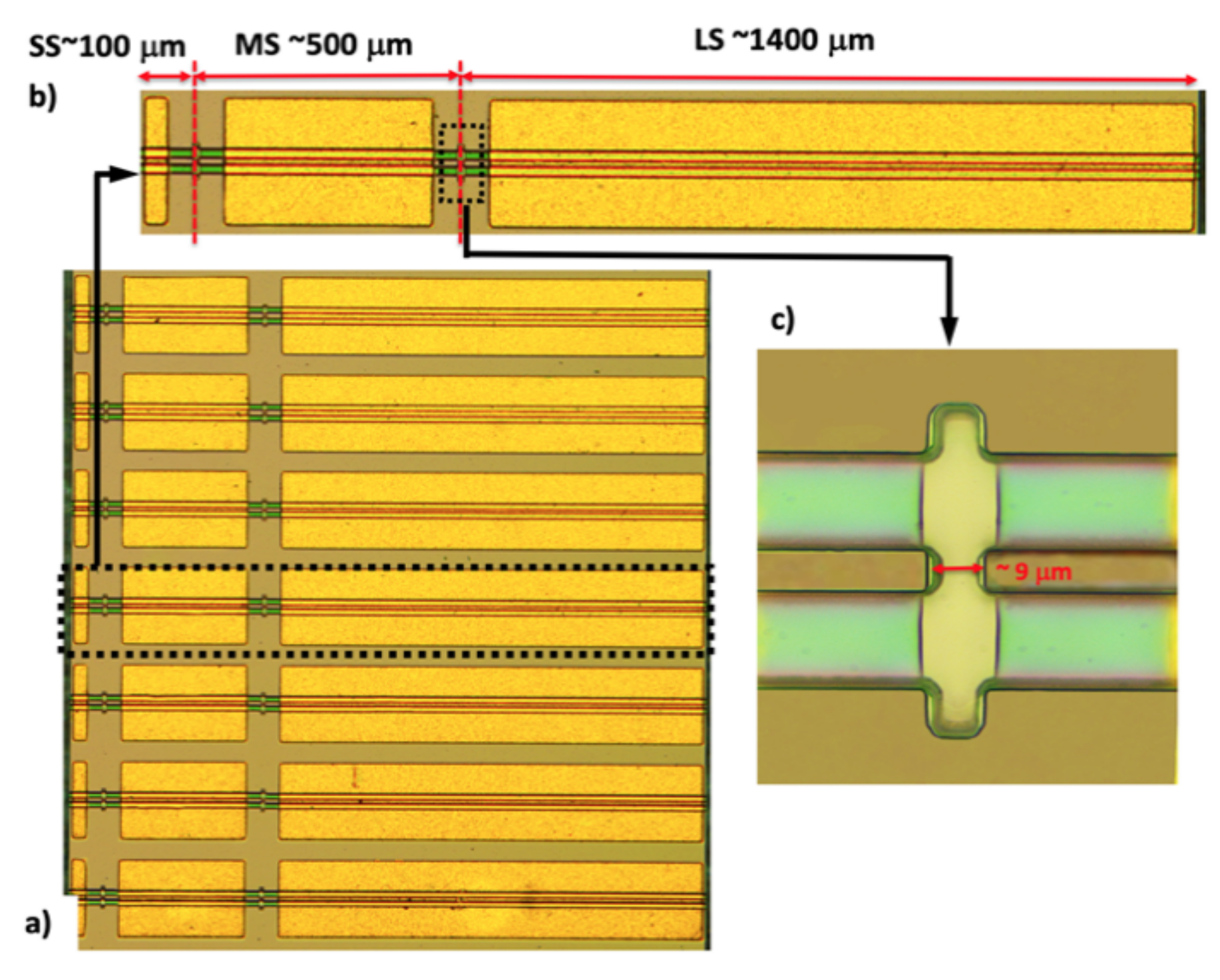
2. Investigated Devices and Fabrication Technology
3. Experimental Results and Discussion
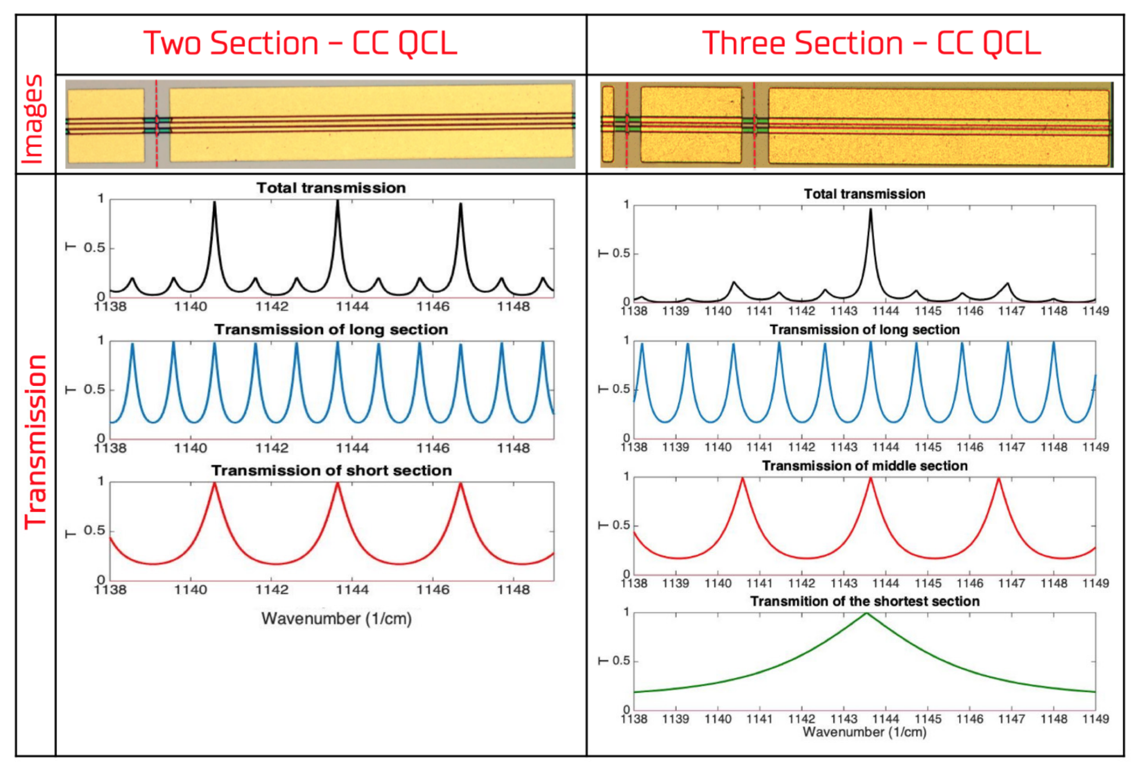
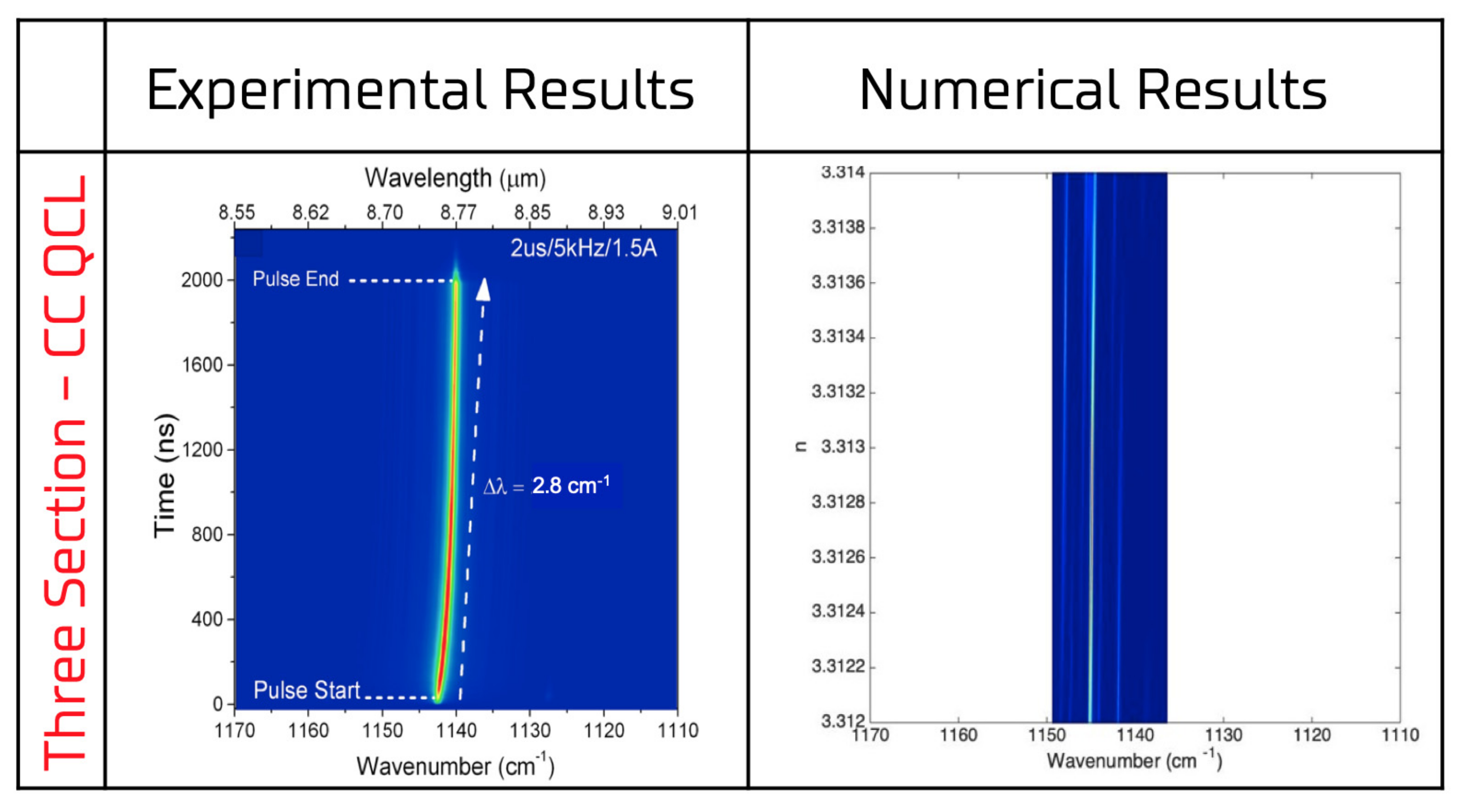
3.1. Numerical Results
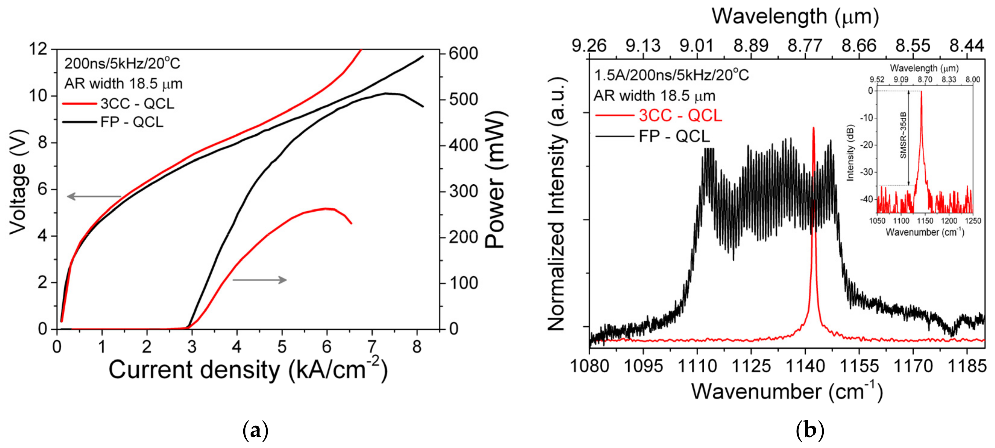
3.2. Experimental Results
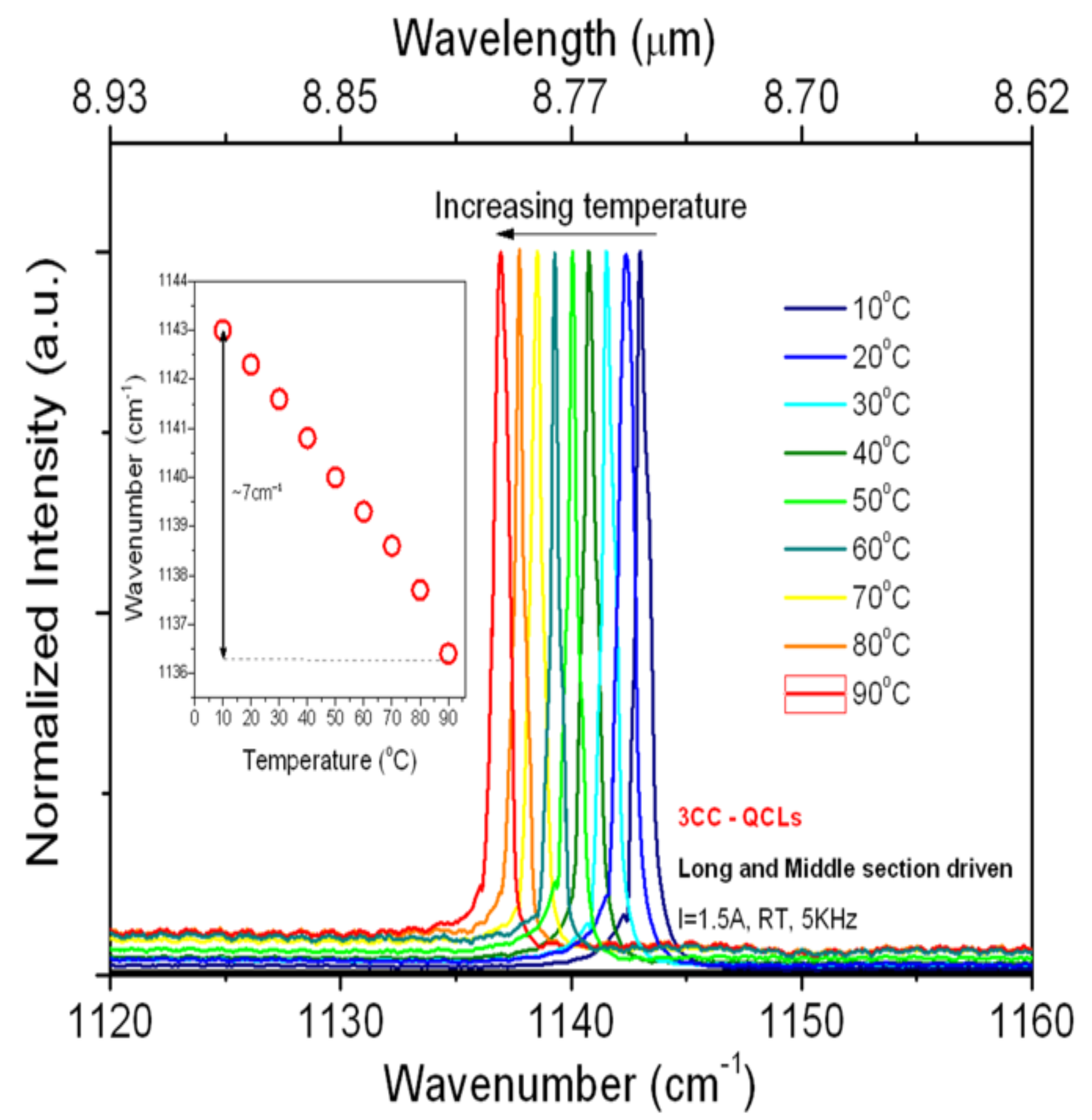
3.2.1. Temperature Tuning
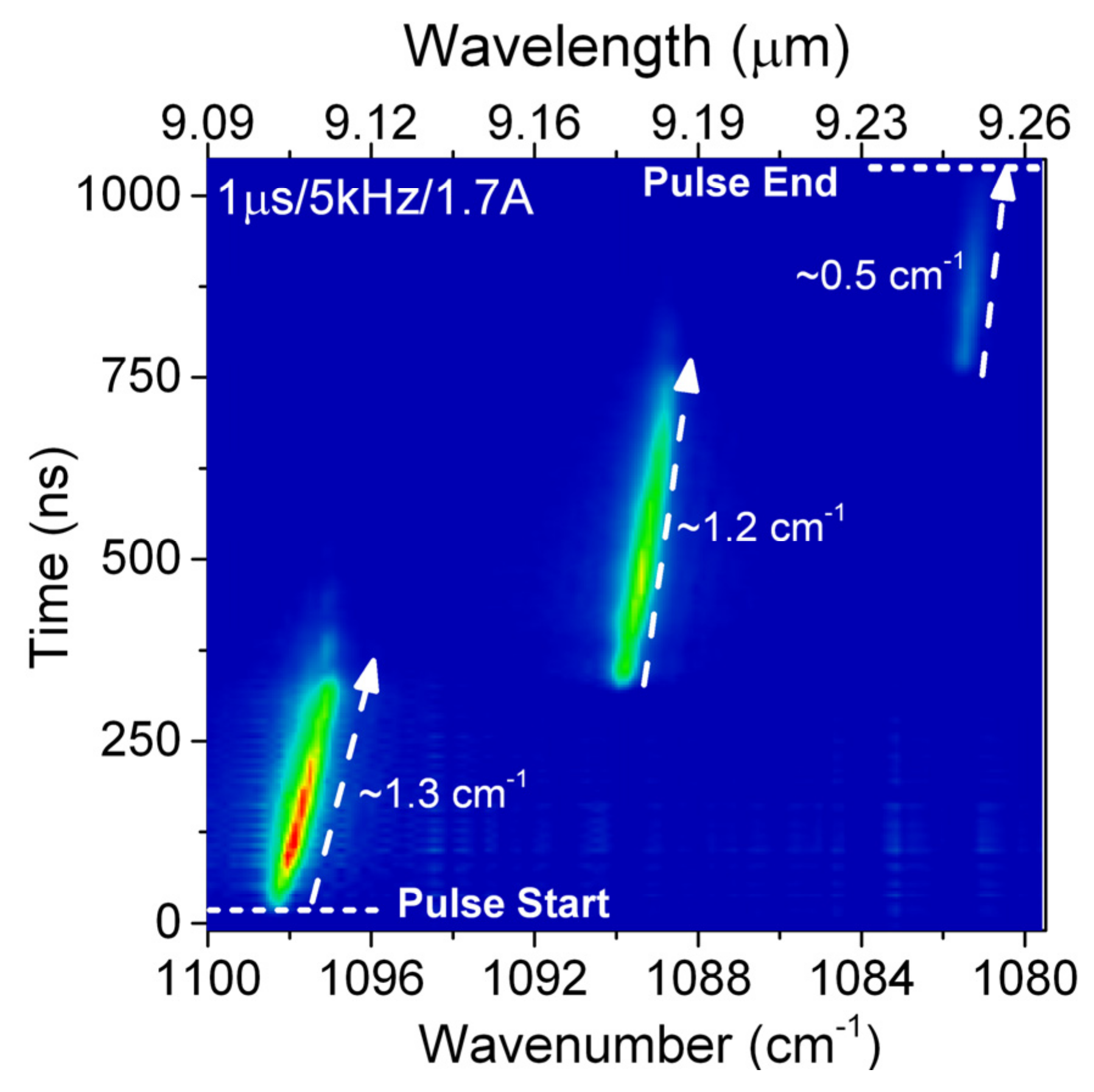
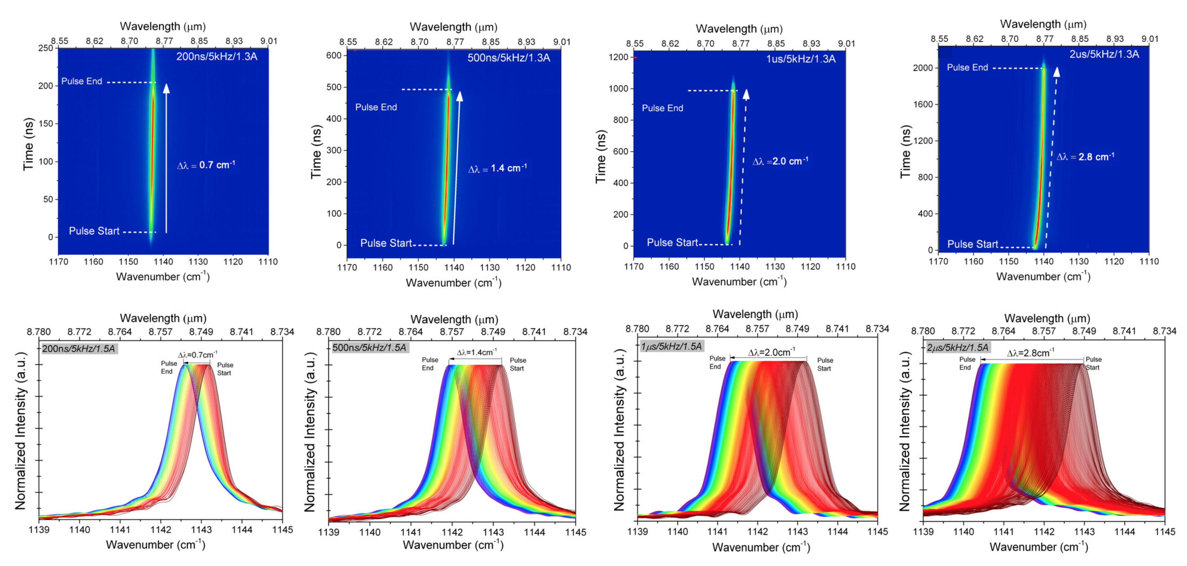
3.2.2. Intrapulse Tuning-Time Resolved Spectra
4. Conclusions
Author Contributions
Funding
Institutional Review Board Statement
Informed Consent Statement
Data Availability Statement
Conflicts of Interest
References
- Curl, R.F.; Capasso, F.; Gmachl, C.; Kosterev, A.A.; McManus, B.; Lewicki, R.; Pusharsky, M.; Wysocki, G.; Tittel, F.K. Quantum cascade lasers in chemical physics. Chem. Phys. Lett. 2010, 487, 1–18. [Google Scholar] [CrossRef]
- Sydoryk, I.; Lim, A.; Jäger, W.; Tulip, J.; Parsons, M.T. Detection of benzene and toluene gases using a Mid infrared continuous-wave external cavity quantum cascade laser at atmospheric pressure. Appl. Opt. 2010, 49, 945–949. [Google Scholar] [CrossRef] [PubMed] [Green Version]
- Schwaighofer, A.; Brandstetter, M.; Lendl, B. Quantum cascade lasers (QCLs) in biomedical spectroscopy. Chem. Soc. Rev. 2017, 46, 5903–5924. [Google Scholar] [CrossRef] [PubMed] [Green Version]
- Wittmann, A.; Bonetti, Y.; Fischer, M.; Faist, J.; Blaser, S.; Gini, E. Distributed-Feedback Quantum-Cascade Lasers at 9 um Operating in Continuous Wave up to 423 K, IEEE Photon. Technol. Lett. 2009, 814, 21. [Google Scholar]
- Hugi, A.; Maulini, R.; Faist, J. External cavity quantum cascade laser, Semicond. Sci. Technol. 2010, 083001, 25. [Google Scholar]
- Cheng, L.; Choa, F.-S. Design and operation of mid-IR integrated DBR tunable lasers. Proc. SPIE 2011, 7953, 79531p. [Google Scholar]
- Wang, C.; Grillot, F.; Kovanis, V.; Even, J. Rate equation analysis of injection-locked quantum cascade lasers. J. Appl. Phys. 2013, 063104, 113. [Google Scholar] [CrossRef] [Green Version]
- Hofling, S.; Reithmaier, J.; Forchel, A. Device performance and wavelength tuning behavior of ultra-short quantum-cascade microlasers with deeply etched Bragg-mirrors. IEEE J. Sel. Top. Quantum Electron. 2005, 11, 1048–1054. [Google Scholar] [CrossRef]
- Colombelli, R.; Srinivasan, K.; Troccoli, M.; Painter, O.; Gmachl, C.F.; Tennant, D.M.; Sergent, A.M.; Sivco, D.L.; Cho, A.Y.; Capasso, F. Quantum cascade surface-emitting photonic crystal laser. Science 2003, 302, 1374–1377. [Google Scholar] [CrossRef]
- Coldren, L.A.; Miller, B.I.; Iga, K.; Rentschler, J.A. Monolithic two-section GaInAsP/InP active-optical resonator devices formed by reactive ion etching. Appl. Phys. Lett. 1981, 38, 315–317. [Google Scholar] [CrossRef]
- Coldren, L.A.; Koch, T.L. Analysis and design of coupled-cavity lasers—Part I: Threshold gain analysis and design guidelines. IEEE J. Quantum Electron. 1984, 20, 659–670. [Google Scholar] [CrossRef]
- Coldren, L.A.; Koch, T.L. Analysis and design of coupled-cavity lasers—Part II: Transient analysis. IEEE J. Quantum Electron. 1984, 20, 671–682. [Google Scholar] [CrossRef]
- Pierściński, K.; Pierścińska, D.; Kuźmicz, A.; Sobczak, G.; Bugajski, M.; Gutowski, P.; Chmielewski, K. Coupled Cavity Mid-IR Quantum Cascade Lasers Fabricated by Dry Etching. Photonics 2020, 7, 45. [Google Scholar] [CrossRef]
- Mikołajczyk, J.; Bielecki, Z.; Stacewicz, T.; Smulko, J.; Wojtas, J.; Szabra, D.; Prokopiuk, A.; Magryta, P. Detection of Gaseous Compounds with Different Techniques Metrol. Meas. Syst. 2016, 23, 205–224. [Google Scholar] [CrossRef]
- Nadeem, F.; Mandon, J.; Khodabakhsh, A.; Cristescu, S.M.; Harren, F.J.M. Sensitive Spectroscopy of Acetone Using a Widely Tunable External-Cavity Quantum Cascade Laser. Sensors 2018, 18, 2050. [Google Scholar] [CrossRef] [Green Version]
- Wojtas, J.; Bielecki, Z.; Stacewicz, T.; Mikolajczyk, J.; Medrzycki, R.; Rutecka, B. Application of quantum cascade lasers in nitric oxide and nitrous oxide detection. Acta Phys. Pol. A 2011, 4, 794–797. [Google Scholar] [CrossRef]
- Gutowski, P.; Karbownik, P.; Trajnerowicz, A.; Pierściński, K.; Pierścińska, D.; Sankowska, I.; Kubacka-Traczyk, J.; Sakowicz, M.; Bugajski, M. Room temperature AlInAs/InGaAs/InP quantum cascade lasers. Photonics Lett. Pol. 2014, 6, 142–144. [Google Scholar]
- Gutowski, P.; Sankowska, I.; Słupiński, T.; Pierścińska, D.; Pierściński, K.; Kuźmicz, A.; Gołaszewska-Malec, K.; Bugajski, M. Optimization of MBE Growth Conditions of In0.52Al0.48As Waveguide Layers for InGaAs/InAlAs/InP Quantum Cascade Lasers. Materials 2019, 12, 1621. [Google Scholar] [CrossRef] [Green Version]
- Bugajski, M.; Gutowski, P.; Karbownik, P.; Kolek, A.; Hałdaś, G.; Pierściński, K.; Pierścińska, D.; Kubacka-Traczyk, J.; Sankowska, I.; Trajnerowicz, A.; et al. Mid-IR quantum cascade lasers: Device technology and non-equilibrium Green’s function modeling of electro-optical characteristics. Phys. Status Solidi (B) 2014, 251, 1144–1157. [Google Scholar] [CrossRef]
- Pierścińska, D.; Pierściński, K.; Iwińska, M.; Kosiel, K.; Szerling, A.; Karbownik, P.; Bugajski, M. Electrical and optical characterization of mid-IR GaAs/AlGaAs quantum cascade lasers. Proc. SPIE 2012, 8432, 84321S. [Google Scholar]
- Pierściński, K.; Pierścińska, D.; Szabra, D.; Nowakowski, M.; Wojtas, J.; Mikołajczyk, J.; Bielecki, Z.; Bugajski, M. Time resolved FTIR study of spectral tuning and thermal dynamics of mid-IR QCLs. Proc. SPIE 2014, 9134, 91341L. [Google Scholar]
- Gadedjisso-Tossou, K.S.; Stoychev, L.I.; Mohou, M.A.; Cabrera, H.; Niemela, J.; Danailov, M.B.; Vacchi, A. Cavity Ring-Down Spectroscopy for Molecular Trace Gas Detection Using A Pulsed DFB QCL Emitting at 6.8 µm. Photonics 2020, 7, 74. [Google Scholar] [CrossRef]
- Pierściński, K.; Bugajski, M.; Czyszanowski, T.; Kolek, A.; Wesołowski, M.; Kuc, M.; Sarzała, R.P.; Dems, M.; Płuska, M.; Pierścińska, D.; et al. Coupled-cavity AlInAs/InGaAs/InP quantum cascade lasers fabricated by focused ion beam processing. J. Phys. Photonics 2019, 1, 015001. [Google Scholar] [CrossRef]


Publisher’s Note: MDPI stays neutral with regard to jurisdictional claims in published maps and institutional affiliations. |
© 2021 by the authors. Licensee MDPI, Basel, Switzerland. This article is an open access article distributed under the terms and conditions of the Creative Commons Attribution (CC BY) license (https://creativecommons.org/licenses/by/4.0/).
Share and Cite
Pierściński, K.; Pierścińska, D.; Sobczak, G.; Kuźmicz, A.; Chmielewski, K.; Krajewska, K.; Gutowski, P. Monolithic, Optically Coupled, Multi-Section Mid-IR Quantum Cascade Lasers. Photonics 2021, 8, 583. https://doi.org/10.3390/photonics8120583
Pierściński K, Pierścińska D, Sobczak G, Kuźmicz A, Chmielewski K, Krajewska K, Gutowski P. Monolithic, Optically Coupled, Multi-Section Mid-IR Quantum Cascade Lasers. Photonics. 2021; 8(12):583. https://doi.org/10.3390/photonics8120583
Chicago/Turabian StylePierściński, Kamil, Dorota Pierścińska, Grzegorz Sobczak, Aleksandr Kuźmicz, Krzysztof Chmielewski, Katarzyna Krajewska, and Piotr Gutowski. 2021. "Monolithic, Optically Coupled, Multi-Section Mid-IR Quantum Cascade Lasers" Photonics 8, no. 12: 583. https://doi.org/10.3390/photonics8120583