1. Introduction
Digital holographic microscopy (DHM) is a powerful technique that allows for the recording and reconstruction of both the phase and amplitude of a light field. In 1967, it was first proposed that a hologram generated by electronic devices could numerically reconstruct the recorded light field [
1]; however, the space–bandwidth product of charge-coupled devices (CCDs) was not sufficiently powerful to realize the idea. This idea was finally realized in 1994 [
2]. In DHM techniques, noise is derived from the interference term that corresponds to the zero-order (DC term), negative first-order (twin-image), and quadratic phase terms (if the hologram is reconstructed directly). However, with the use of electronic devices to record the hologram, image processing via computation can be implemented, including the numerical reconstruction of the light field to retrieve information regarding objects, which are fundamental to DHM. Hence, in the past few decades, there have been attempts to suppress intrinsic noise in DHM. Various methods have been proposed to eliminate the interference of the zero-order, conjugate, and quadratic phase terms [
3,
4,
5,
6,
7,
8]. DHM has been widely used to observe biological cells [
9,
10], such as cancer cells and
E. coli cells, or to observe the mechanical elements in industrial applications [
11,
12]. The optical system of DHM can be divided into bright- and dark-field DHM configurations. Dark-field DHM is currently used to observe samples such as larvae and nanoparticles [
13,
14]. The main concept of dark-field DHM is to highlight the sharp features of an image while degrading the background and low-spatial-frequency information. Conventionally, this is achieved by using a piece of metal and a condenser lens that has a higher numerical aperture than that of the microscope objective to restrict illumination on the object [
15]. Dark-field DHM can simultaneously suppress scattering noise and enhance contrast [
16]. In addition, multiple holograms can be recorded using dark-field DHM, and the reconstructed image includes suppressed speckle noise [
13]. In 2014, Faridian et al. [
17] studied opposed-view dark-field DHM and obtained two images using bright-/dark-field objective images with relative viewing angles (top and bottom) and simultaneous full-frame recordings. The research results demonstrated that the contrast of the reconstructed image was improved. In 2018, Trujillo et al. [
18] adopted a digital lensless holographic microscopy system and proposed a numerical method to obtain dark-field holograms with improved image contrast of samples (such as paramecium). Quantitative measurement of image contrast is usually evaluated by calculating the standard deviation of the image [
19,
20]. A higher value of standard deviation means a better image contrast. In DHM, speckle noise contrast can be used to evaluate speckle noise. The smaller the value of speckle noise contrast, the less speckle noise of the reconstructed image [
21,
22].
Based on this development trend, we observe that dark-field techniques are emerging in the field of holography. However, conventional dark-field DHM requires specialized optics and, thus, obtaining dark-field images has a high cost. Once the system is amended to the dark field, it no longer yields bright-field images. Furthermore, owing to the limited cone of light in conventional dark-field DHM, a high illuminating intensity is required to produce a reasonable image signal, which may damage the sample being tested. Thus, we developed a novel dark-field DHM technique called interference-dark-field digital holographic microscopy (IDFDHM).
IDFDHM uses the interference-dark-field technique to suppress scattering noise. This technique is adopted to enhance the image contrast in DHM, and no specialized or expensive optical components or accessories are required.
2. Theoretical Background
The configuration of IDFDHM is based on a Mach–Zehnder interferometer. The experimental setup, based on an in-line DHM system, is illustrated in
Figure 1. A diode-pumped solid-state laser operating with a wavelength of 532 nm was used as the light source and the output optical power was fixed at 0.3 W. A polarization beam splitter (PBS) and two half-wave plates (HWP 1 and HWP 2) were used to adjust the intensity ratio of the object light and the reference light. The polarizer (PL) checked the polarized state of the light source. HWP 2 was used to adjust the polarization of the light waves to optimize interference effects. Neutral density (ND) filters were set up separately for the object and the reference light paths, which could be used to independently and further adjust the light intensity. A lens was set up on the object light optical path to focus the object light beam, and a sample was placed on the focal plane. The power of the laser beam imping on the sample was 30 mW. The samples were magnified using a microscope objective (MO, 20X, NA = 0.40, Edmund Optics Inc., Barrington, NJ, USA). The glass plate of the reference light optical path frame had a thickness of 177 μm and a refractive index of 1.52, and it was used as a phase object to adjust the phase of the reference light wave. Thereafter, a spatial filter (SF, 40X, NA = 0.65, Edmund) was set up to match the secondary phase term of the object light wave so that it compensated for the quadratic phase term [
7]. A mirror and a beam splitter (BS) were used in the optical path to guide the light beam in such a way that the object light and the reference light overlapped to generate interference. The two beams had the same vertical polarization states. Finally, the interference pattern was recorded using a Pixela-150SS CCD camera (1392 × 1040 pixels) with an area of 0.650 × 0.484 cm
2 of a 4.6 μm pixel pitch. In this study, in order to make comparisons with the experimental results of IDFDHM, we placed a mask (solid metal sheet with a diameter of 2.5 mm) at the back of the MO, as shown in
Figure 1, and obtained a dark-field image through spatial filtering [
15]. The control setup (conventional dark-field DHM) in this comparison is referred to as the control set. We used the angular spectrum method [
23] to perform numerical reconstruction.
IDFDHM is based on two techniques that we developed previously: arbitrary micro-phase shifting [
8] and virtual lens compensation [
7]. The virtual lens compensation technique suppresses the quadratic phase term by using two waves that have the same quadratic phase term. This is achieved by simply employing two identical microscope objective lenses in each arm.
Let
,
,
,
, and
represent the light field, amplitude, phase, wavelength, and radius of curvature, respectively, while the subscripts O and R denote the qualities associated with the object wave and reference wave, respectively, as expressed in Equations (1) and (2). Upon interference, the quadratic phase terms (including phase aberrations) cancel each other out, and the interference pattern
is the result of the interference of two plane waves, as expressed in Equation (3).
Next, consider a thin and homogeneous phase object (such as a glass plate) stationed on a rotational stage and illuminated with a collimated beam in such a way that the phase of the reference beam is modulated by adjusting the angle of incidence.
Figure 2 shows the wavelength of incident light
. The thickness and refractive index of the phase object are represented by
and
, respectively, and
denotes the refractive index of air. The angles of incidence and the angle of refraction of the phase object before rotation are
and
, respectively, and the angles of incidence and refraction of the phase object are
and
, respectively. If the angle of incidence of the incident light is known, it can be changed by rotating the phase object; the amount of phase modulation in the reference wave (Equation (4)) can be further derived from the optical path difference (Equation (5)) before and after the incident angle is changed.
IDFDHM uses an arbitrary micro-phase-shift modulation method [
8] to achieve destructive interference between the object light and reference light. The main method is to change the phase of the reference light to achieve destructive interference by using phase shift technology. Under the condition of destructive interference, IDFDHM captures the image of the dark field and reconstructs the object information.
Scattering is a major problem that degrades the fidelity of an image. It is caused by sources that are small in size compared to the wavelength of light, such as surface roughness and dust particles. Nevertheless, because these scattering sources are small, the optical path length, or the phase delay induced by them, is also small. Thus, we may exploit this optical property to develop a novel dark-field microscopy technique. Consider that the argument of the cosine function comprises the phase information of the object wave , reference wave , scattering sources , and glass plate for phase shifting, respectively. Given that , which is negligible compared to the amount of phase to be modulated, we can modulate in such a way that the region of interest is subject to destructive interference. In such a situation, the scattering sources are in a state of “darkness” thus, the scattering effect is removed from the object, as there is “no light”. In contrast to the conventional dark-field method, in which limited lighting is available, our proposed method simply “turns the lights off”.
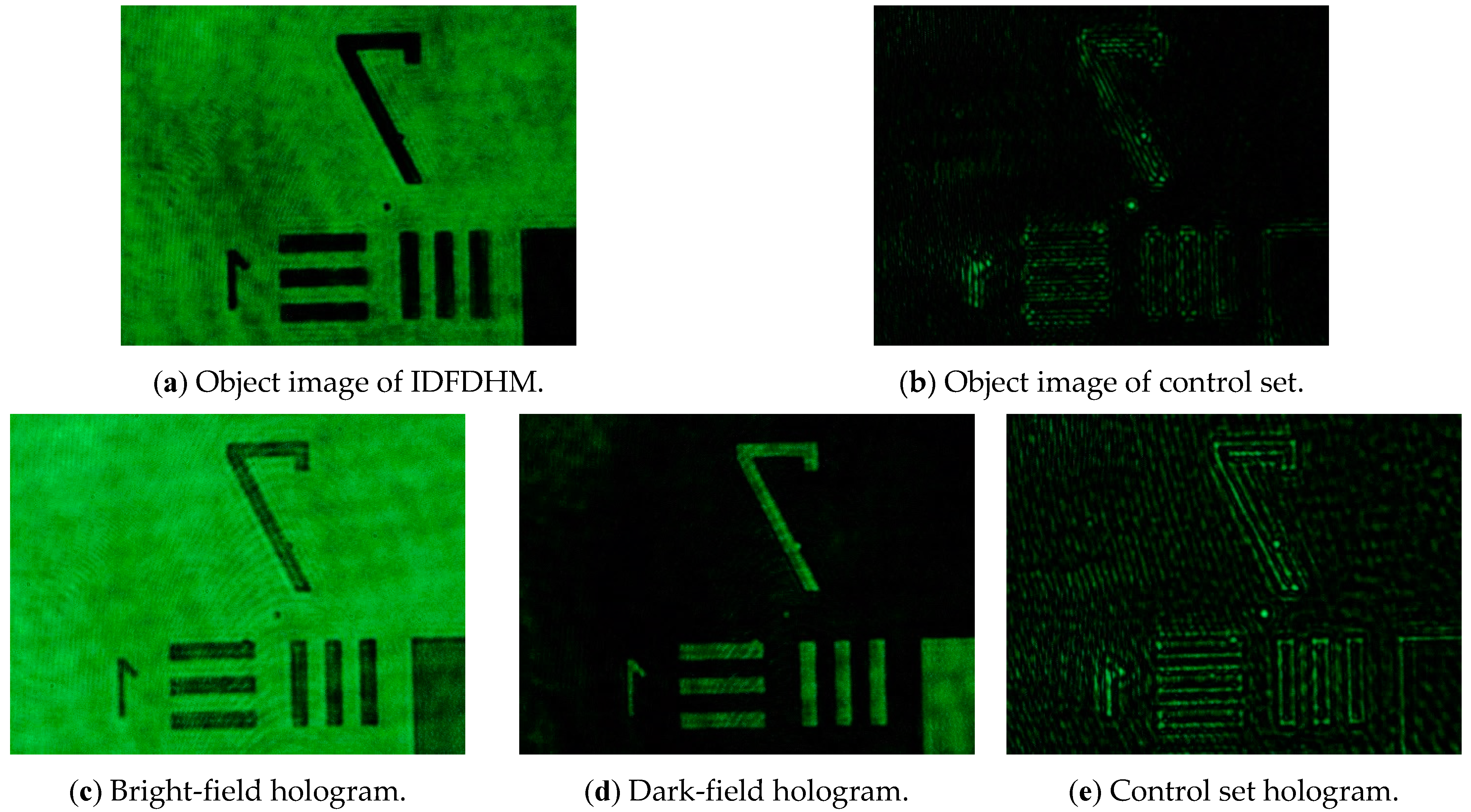
Thereafter, we obtained a result that was similar to conventional dark-field microscopy—only the negative background was manipulated by destructive interference, as shown in
Figure 3.
Figure 3a,b show the object light observed in IDFDHM and the control set, respectively. A resolution of 128 line pairs/mm (one element of group 7, USAF 1951 resolution target) was achieved. In contrast to conventional dark-field microscopy, low spatial frequency information is preserved, allowing for more variation in image processing. The interference fringe pattern was then recorded in the hologram (
Figure 3c,d). Because IDFDHM uses a phase-shifting technique to obtain destructive interference with a background, switching from a dark field to a bright field, or vice versa, is simple, convenient, and cost effective. Additionally, IDFDHM does not restrict the illumination path and does not require high-intensity illumination, and the sample being tested is not damaged. Moreover, the edges and background are clearly distinguishable, without a loss of information.
3. Experimental Results and Discussion
IDFDHM can perform bright-field and dark-field imaging separately. The results regarding the bright field are presented first. The experiments were conducted using the configuration that is shown in
Figure 1. In the experiment, a positive target (USAF 1951, positive target, Edmund Optics) was used as the sample. The CCD records the object and reference lights separately, and the two light waves interfere with each other to create a hologram. The CCD records the interference between the two light waves (object and reference lights) as a hologram and records the object and reference lights, separately, to eliminate the DC term. The DC term is eliminated by subtracting the intensities of the object wave and the reference wave from hologram [
8]. The reconstructed image in the bright field is shown in
Figure 4a. The resolution in this Figure is 128 line pairs/mm or 3.91 μm.
Thereafter, an IDFDHM experiment was conducted in the dark field. The CCD was used to record the object light and the reference light separately; thereafter, the two light waves interfered with each other to record the hologram. Subsequently, the interference state was modulated by destructive interference. Next, a dark-field hologram was recorded. The reconstructed image of IDFDHM in the dark field is shown in
Figure 4b. As shown in the Figure, the image is sufficiently clear to identify the line pairs in group 7, element 1 on the resolution target, where the line pair density is 128 line pairs/mm.
To compare the results of the IDFDHM dark-field experiments with the results obtained using other techniques, a control set experiment was conducted. The dark-field object light images that were obtained through spatial filtering in this study are shown in
Figure 3b. The CCD was used to record the object light and the reference light separately, and the hologram was recorded after the interference between the reference light and the object light. The reconstructed image of the control set is shown in
Figure 4c. Although
Figure 4c,b show the same resolution (3.91 μm), the control set configuration exhibits the disadvantages of traditional dark-field microscopy, such as signal loss and an unfiltered background. As observed in
Figure 4b, the image that was reconstructed by the IDFDHM method has clear edge contours and retains intact object information. A review of the literature shows that high-contrast images have high standard deviations [
19,
20]. Therefore, standard deviation values were used to analyze the image quality. The reconstructed image was a grayscale image, as shown in
Figure 4. By calculating the standard deviation of each pixel intensity (gray level), this analytical method provided the degree of grayscale intensity distribution in the image. The standard deviations of
Figure 4a–c are 40.8, 49.3, and 34.3, respectively. A comparison between the standard deviation of the IDFDHM of the dark-field state and the control set configuration reveals that the standard deviation increased by 43%.
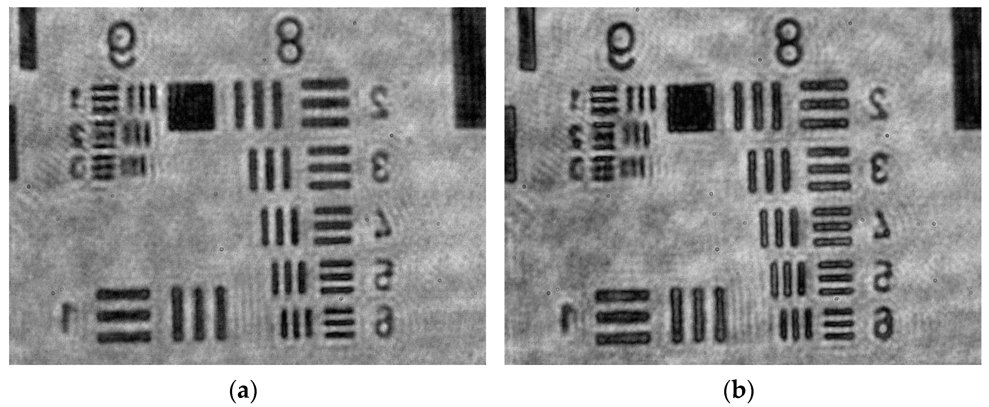
In addition, we investigated the maximum resolution of the proposed system. In the experiment, a high-resolution positive target (USAF 1951 Hi-Resolution Target, positive target, Edmund Optics) was used as the sample.
Figure 5 shows the best resolution image of the IDFDHM system.
Figure 5a,b show the reconstructed images of the bright-field and dark-field IDFDHM, respectively. The result shows a line pair with a resolution of 574.7 line pairs/mm for the second element of group 9 in the target group. The image resolution of the IDFDHM system is up to 0.87 μm. The standard deviations of
Figure 5a,b are 39.9 and 43.1, respectively.
After determining the resolution of the system, other samples were used for testing. A commercial microlens array from SUSS MicroOptics (refractive index,
n = 1.457; pitch = 100 μm) was used as the sample.
Figure 6a,b show the reconstructed 3D information of a microlens array in the bright-field and dark-field IDFDHM, respectively. The specifications (provided by the manufacturer) of the lens sag and lens width of the microlens array are 9.8 μm and 95.0 μm, respectively. The experimental results indicate that the lens sag and lens width of the microlens array are 9.3 and 94.2 μm, respectively, as shown in
Figure 6a. The reconstruction result in the dark field indicates that the lens sag and lens width are 9.4 and 94.8 μm, respectively. The results in the dark field were closer to the manufacturer’s specifications than the results in the bright field.
Conventional dark-field DHM uses optical stops (or spatial filters) to suppress low-spatial-frequency signals. Theoretically, the high-spatial-frequency signals of the images can be highlighted; however, in practice, the stops and/or spatial filters induce diffraction and speckle disturbance into the intended signals, which can affect the reconstructed image. Additionally, the conventional DHM technique also limits the effective illuminance, which, in turn, requires a higher energy illumination of the probe light and may damage the samples. However, the IDFDHM system has the advantage of switching between bright-field and dark-field microscopy, thereby avoiding the risk of damaging the sample as a result of high-intensity illumination. In the proposed configuration, no specialized optical elements or dark-field microscopy objectives are required, and only bright-field DHM can be used.


