Communication

Adaptive Fiber Ring Laser Based on Tapered Polarization Maintaining Fiber in Sagnac Loop for Temperature and Salinity Sensing

1
Department of Electrical and Electronic Engineering, Southern University of Science and Technology, Shenzhen 518055, China
2
Department of Applied Physics, Hong Kong Polytechnic University, Hongkong 999077, China
3
Peng Cheng Laboratory, Shenzhen 518005, China
*
Authors to whom correspondence should be addressed.
These authors contributed equally to this work.
Photonics 2023, 10(5), 599; https://doi.org/10.3390/photonics10050599
Submission received: 17 April 2023 / Revised: 17 May 2023 / Accepted: 18 May 2023 / Published: 22 May 2023
(This article belongs to the Special Issue Advanced Photonic Sensing and Measurement)

Abstract

:
An optical fiber ring laser (FRL) cavity-based sensitive temperature and salinity sensor is proposed and experimentally demonstrated. The sensor consists of a Sagnac loop with a waist of 15 µm and a total length of 30 cm made of tapered polarization-maintaining fiber (PMF). Sagnac loop dual parameter sensing was theoretically modeled and presented. The salinity sensitivity of 0.173 nm/‰ was made possible by the efficient interaction between the tapered PMF cladding mode and the external refractive index. In addition, temperature sensitivity of 0.306 nm/°C was achieved through ultrahigh birefringence of PMF. Apart from that, the previous sensing system used a broadband light source (BBS) as the input light, resulting in a wide bandwidth and a poor signal-to-noise ratio (SNR). The Sagnac loop integrated into the FRL system can achieve a high SNR of approximately 50 dB and a narrow bandwidth of 0.15 nm while serving as the filter and sensor head. Additionally, the developed sensor has the advantages of simple design, low cost, and easy fabrication. It can also extend sensing distance indefinitely within a given range, which is anticipated to have positive effects on the testing of marine environments in laboratories.

1. Introduction

The marine ecosystem has suffered recently as a result of the rapid economic expansion of coastal regions around the world, and both the quantity and variety of pollutants entering the sea have greatly grown. For changes in the marine environment, coordinating the design of coastal economic growth, and improving the marine environment, direct monitoring of seawater temperature and refractive index is crucial [1,2,3,4]. Fiber optic sensors stand out among the rest thanks to features such as low cost, low weight, small size, and immunity to electromagnetic radiation. Gradually, it is being used for the measurement of temperature [5,6,7], salinity [8,9,10], and depth [11,12,13] in the maritime environment. Wang et al. proposed a sensor based on surface plasmon resonance (SPR) fiber for simultaneous measurement of salinity and temperature. The sensor forms an SPR by gold-plating one side of the optical fiber. The sensitivity of temperature and salinity are −316.72 pm/°C and 429.72 pm/‰, respectively [14]. However, the sensitivity for long-term operation will decrease due to the timeliness of the long-term composite of gold film and optical fiber. To achieve dual sensing of temperature and salinity, Zhao et al. proposed employing a Mach Zender interferometer structure with tapered side hole optical fiber [15]. Nevertheless, due to the construction of special optical fiber, their air holes are vulnerable to collapsing while being drawn. An et al. proposed a three-parameter fiber optic sensor with a cascaded Fabry Pérot (FP) cavity and chirped fiber Bragg grating. The vernier amplification effect allowed for an increase in depth sensitivity to 116.85 pm/m [16]. However, its system structure is complex, with low-temperature sensitivity and high stability requirements. To satisfy the development trend of “diversification, real-time, long-term, and three-dimensional” in marine water monitoring, there is an urgent need for a new type of fiber optic sensing system.
“Real-time observation-model simulation-data assimilation-business application” makes up the optimum three-dimensional real-time monitoring system for optical fiber maritime monitoring systems. However, due to limitations imposed by its inherent features, the classic sensor using a broadband light source (BBS) as the light source inevitably ran into issues with demodulation. These issues include poor signal-to-noise ratio (SNR) and huge bandwidth, which is a disastrous blow to data assimilation. As a result, various demodulation algorithms and new light sources for sensing ocean temperature, salinity, and depth have been proposed [17,18,19,20,21,22]. Using single-mode fiber and coreless fiber, Xu et al. created an FP interferometer for salinity monitoring [23]. By utilizing the advantages of good SNR and the narrow bandwidth of a fiber ring laser (FRL) cavity, an intensity demodulation scheme with a detection limit of 0.0023‰ has been achieved. Our research team proposes that doped optical fibers inside the FRL structure be used to directly monitor temperature and refractive index [24,25], eliminating the need for an extra filter and sensor head design. Comparatively, the material properties of optical fibers result in low refractive index sensitivity. Furthermore, a speckle pattern fiber sensor based on coreless fiber and multimode fiber was proposed by Lu et al. [26]. The refractive index of seawater was measured by extracting the eigenvalues of the gray matrix of the output-speckle pattern, with a detection resolution of 3.90 × 10⁻⁴. Using high-speed cameras instead of an optical spectrum analyzer (OSA) improves the resolution while considerably lowering system costs. However, this method involves the transmission of light into space, which drastically reduces the system’s stability. To create an effective and sensitive multi-parameter marine monitoring instrument with small volume, less solvent or no solvent, strong anti-interference ability, high SNR, and anti-corrosion, it is necessary to develop a new type of fiber sensor probe or monitoring method with strong tolerance to the extreme environment.
In this paper, a brand-new FRL sensing system is proposed for the dual parameter monitoring of salinity and temperature. The experimental results demonstrate that the designed tapered polarization maintaining fiber (PMF) -based Sagnac loop can respond sensitively to ambient refractive index and temperature changes. In the laboratory environment, the salinity sensitivity is as high as 0.173 nm/‰, while the temperature sensitivity is maintained at 0.306 nm/°C. At the same time, the FRL system further improves the SNR to 50 dB and narrows the bandwidth to 0.15 nm. Furthermore, through effective encapsulation, the proposed sensing system has the potential to be used for monitoring the maritime environment.

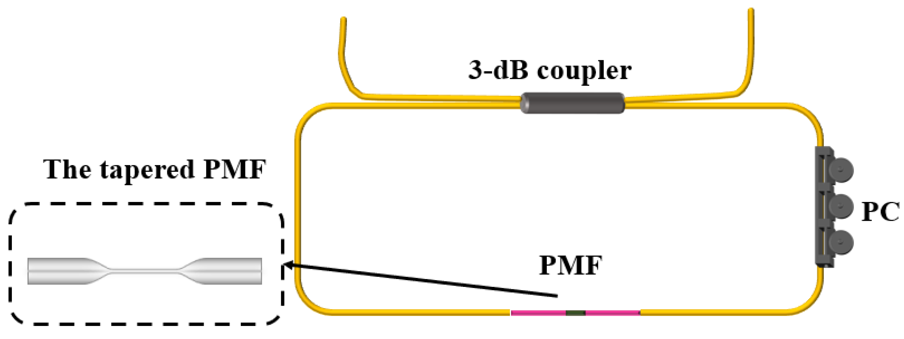
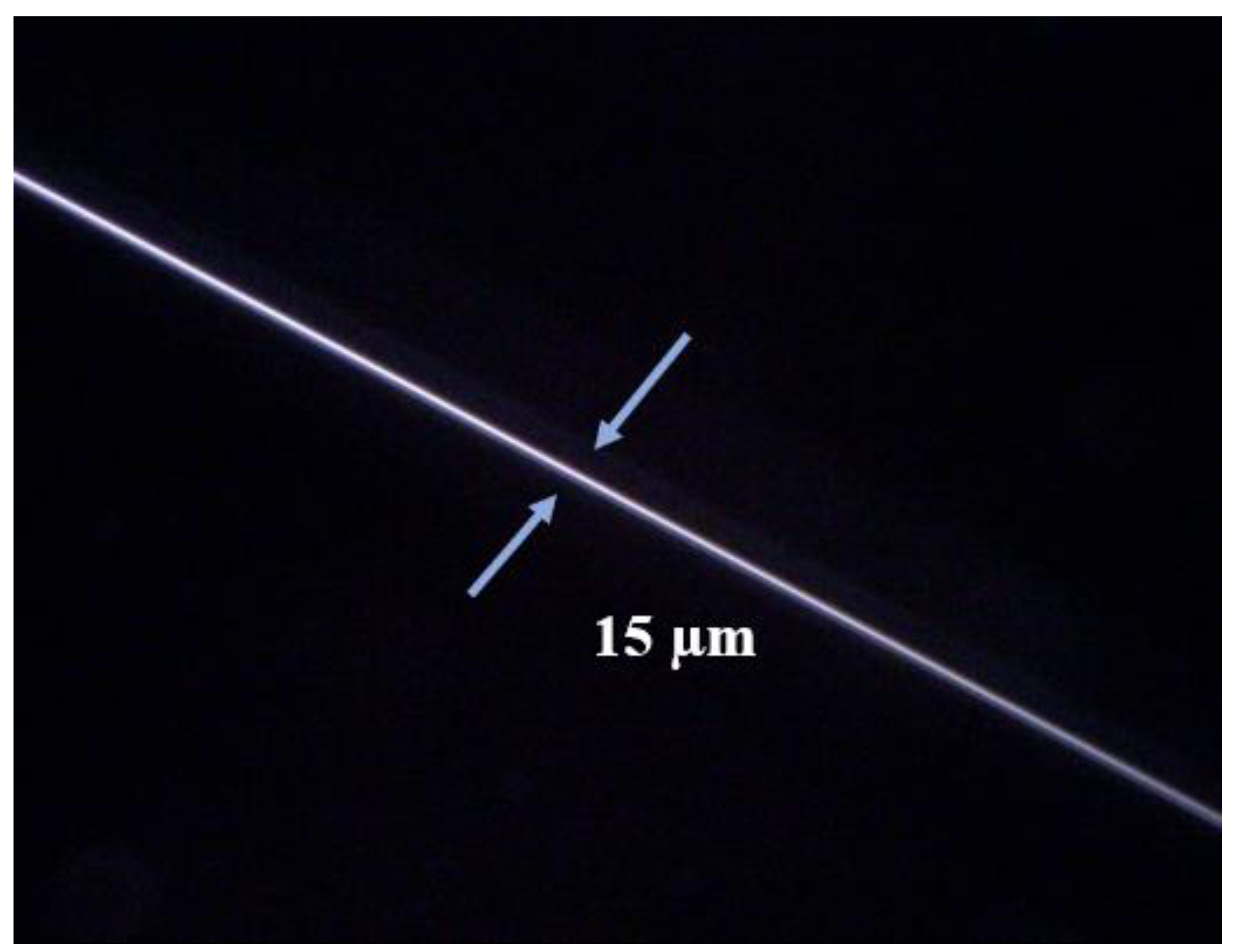
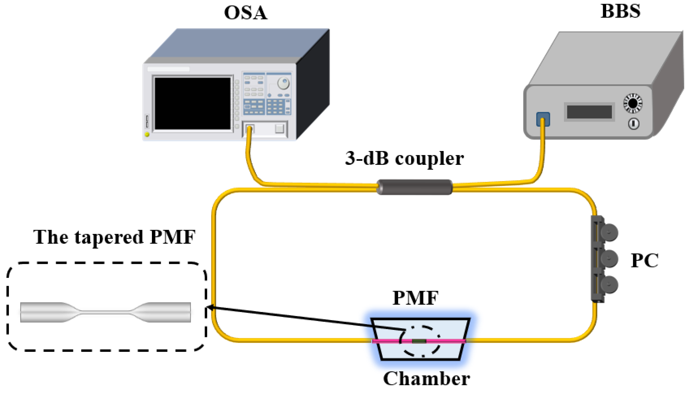
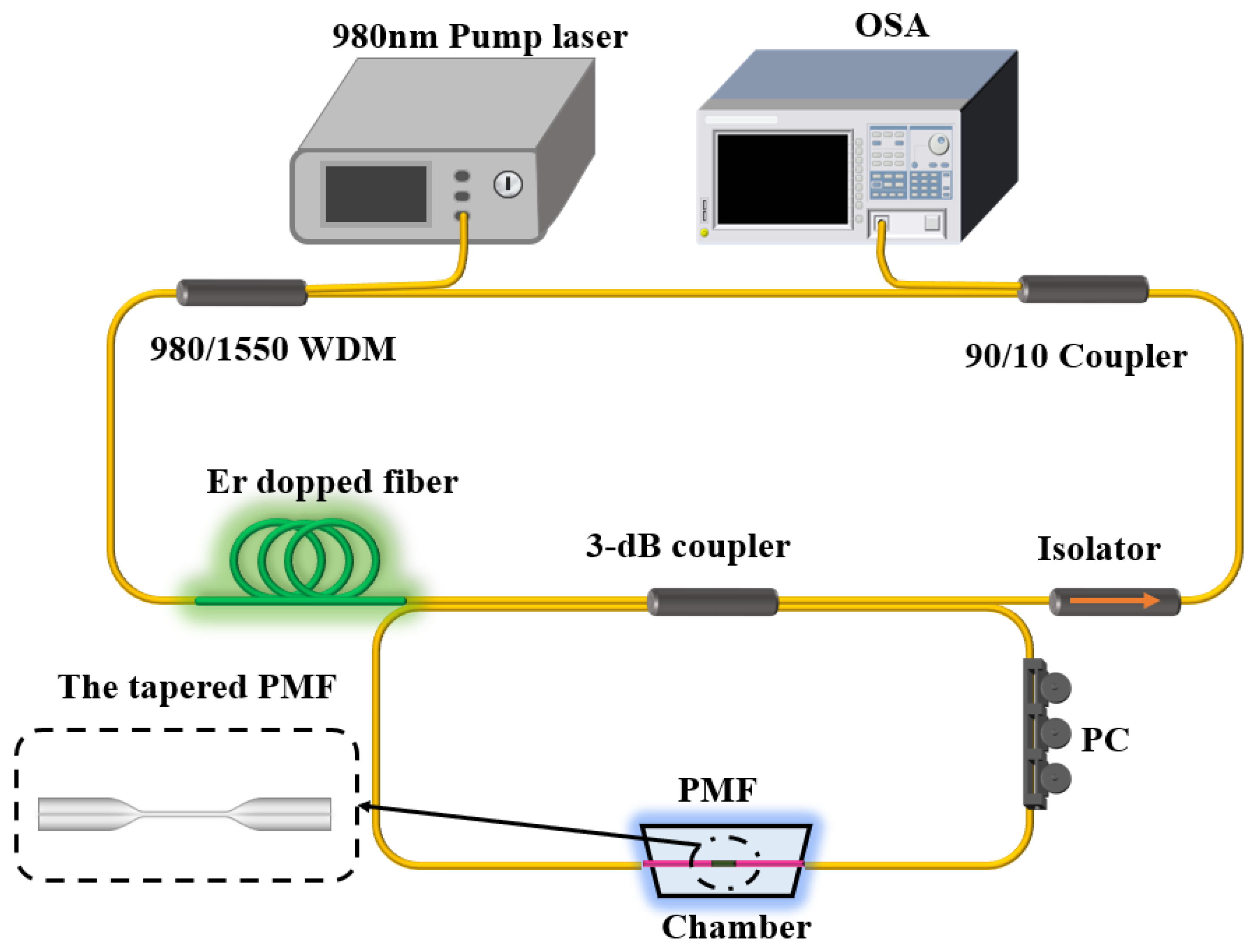
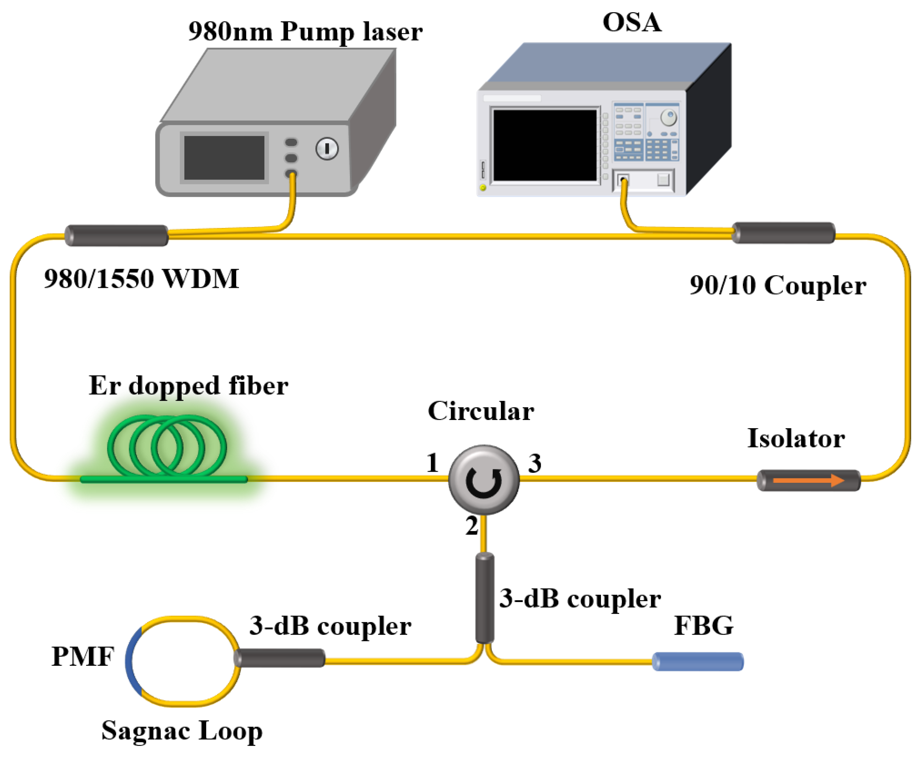
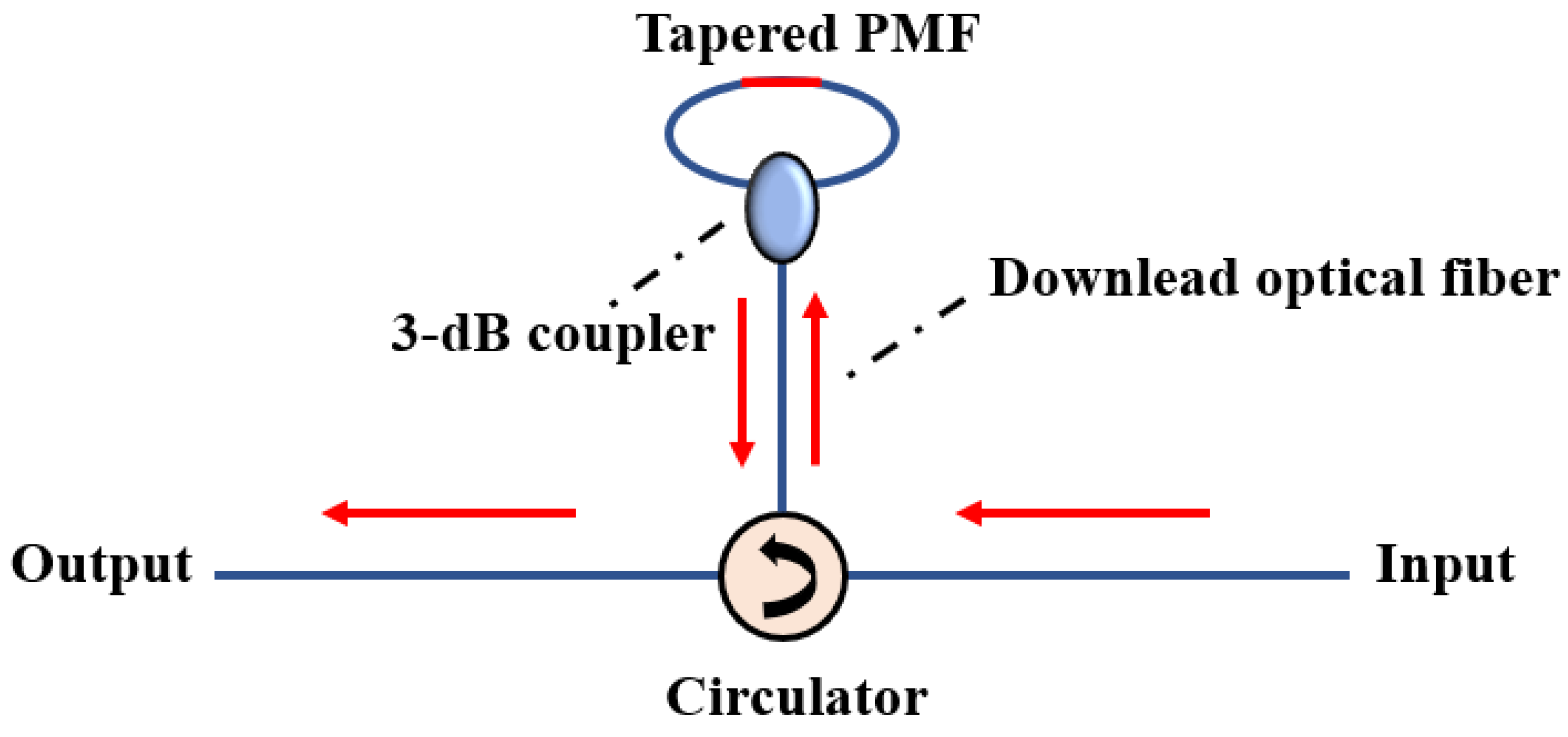
2. Working Principle and Experimental Setup
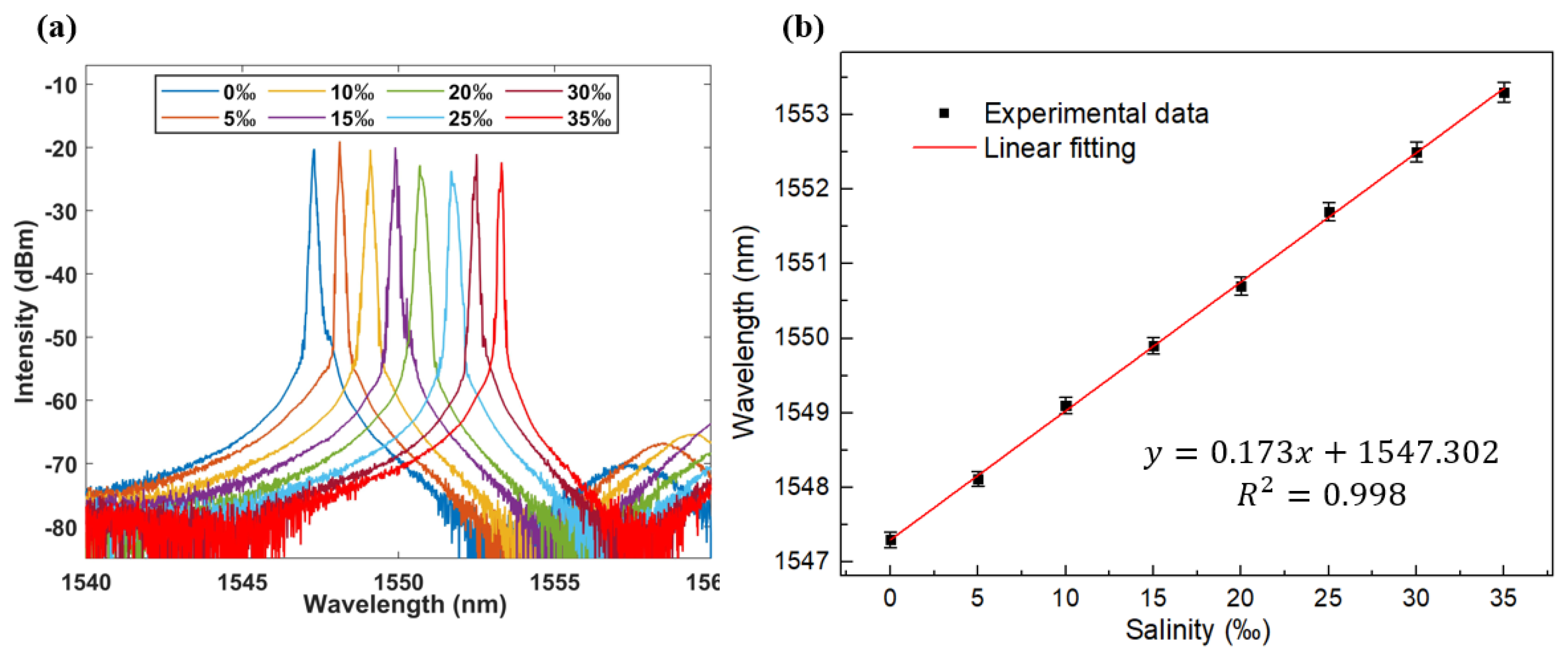
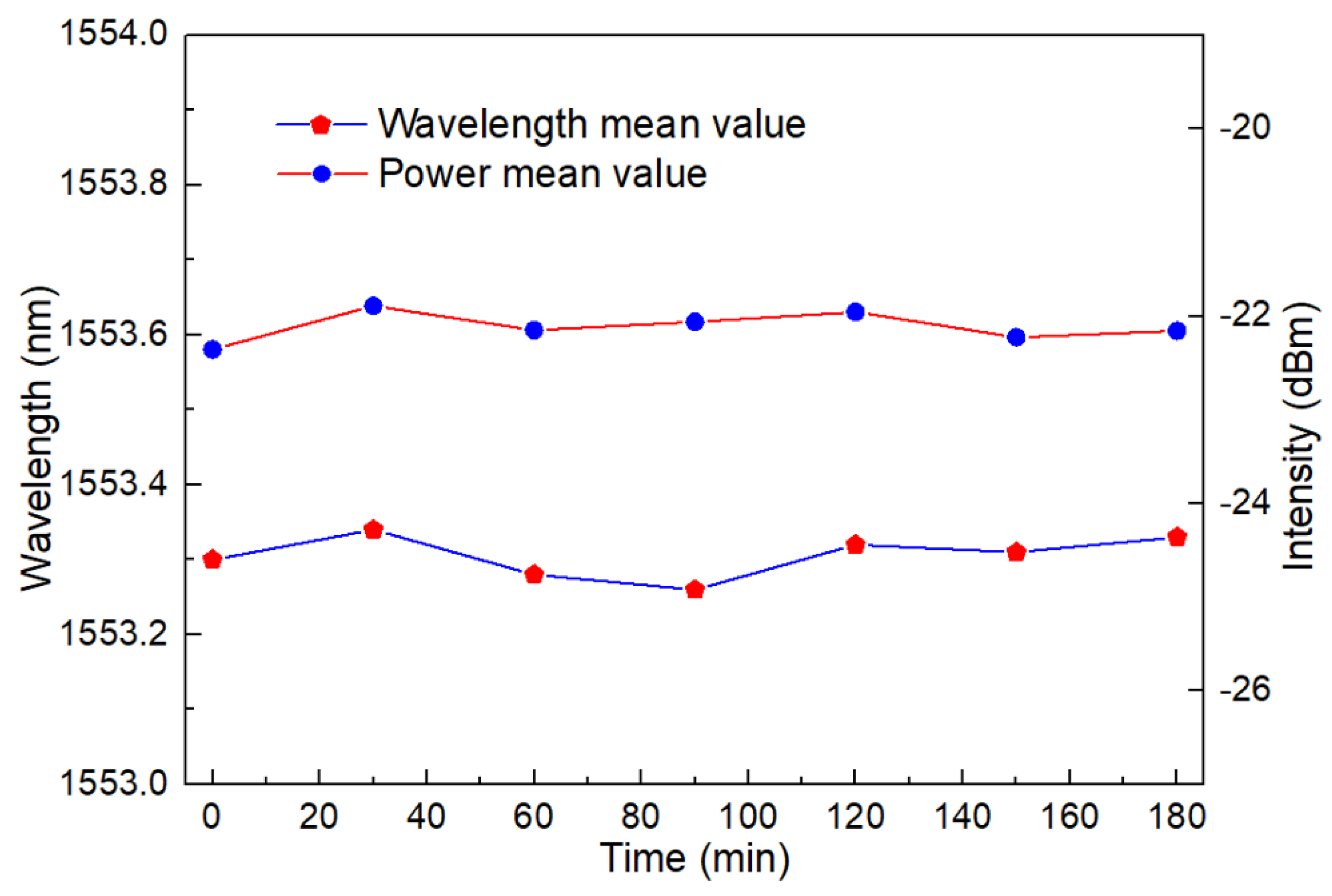
Figure 1 depicts the schematic representation of the Sagnac loop fiber construction with a tapered PMF. A 3-dB coupler separates light into forward and reverse beams. Following that, two light beams move in opposite directions along the suggested Sagnac loop based on a tapered PMF fiber construction. Light input along both directions enters the tapered PMF, and due to mode mismatch between fibers, many guiding modes are excited in the tapered PMF. A portion of the guided modes propagate along the fiber core, while another portion of the guided modes propagate to the external environment after reaching the tapered region, and then recouple to the PMF fiber core after passing through the tapered region. Some core modes will couple to the cladding of the PMF during light propagation, creating cladding modes. The opposite process of light propagation occurs when moving in a counterclockwise manner. Phase difference causes the light traveling clockwise and counterclockwise in the Sagnac loop to interfere with the output port of the 3-dB coupler. Utilizing a tapering machine (AFBT-8000LE-H0, Shandong Coupler Technology Co., Ltd., Jinan, Shandong, China), tapered PMF is created by heating hydrogen gas combustion. By setting different pulling lengths, tapered fibers of different thicknesses can be obtained. A tapered PMF with a width of 0.15 µm in the waist area can be produced on the original 30 cm long PMF by controlling the parameter of pulling length to 14,000 µm, as shown in Figure 2.
Using a 3-dB coupler, the input light is split into two back-propagation beams. The birefringence of PMF results in phase discrepancies between these two beams. At the 3-dB coupler’s output port, two beams can be joined again to create an interference spectrum. The following equation gives the phase difference [27,28]:
φ = 2 π B L λ
where λ is the central wavelength of the input light, B is the birefringence of the total Sagnac loop fiber structure, and L represents the length of the PMF including the tapered region. If the input intensity is I i n , the output intensity at the coupler of the optical spectrum can be approximated as [29,30]:
I = I i n ( 1 c o s φ ) 2
Additional birefringence B can be introduced when the temperature of PMF varies [31]. Furthermore, a tapered PMF produces two fundamental modes that are orthogonally polarized and have various effective refractive indices [32]. The phase difference will vary as a result [33]. Changes in temperature and refractive index have an impact on the interference spectrum that results from the interaction of the two polarization modes. The displacement of the interference wavelength with respect to changes in the ambient refractive index and temperature is used to characterize the sensitivity, which can be predicted using the formula below [34]:
S R I = d λ d n = λ B n B λ B λ
S T = d λ d T = λ B T B λ B λ
where n is the surrounding refractive index and T is the surrounding temperature.
The experiment was initially observed in the device as depicted in Figure 3. To create the interference spectrum, which is demodulated by the OSA, the BBS is transmitted forward and reverse through the 3-dB coupler at the same time in the Sagnac loop with the PMF length equal to 30 cm. The interference spectrum’s wavelength will shift when the refractive index or temperature is adjusted, and the sensor responsiveness can be determined by noting the offset. This portion of the experiment aims to confirm that the Sagnac loop can function well as a filter in the laser cavity.
After the interference phenomenon of the intended sensor is successfully validated, the tapered PMF-based Sagnac loop structure is inserted into the laser cavity to serve as a filter and sensor head. Since the interference spectrum modulates the FRL system, the laser will output laser light in the gain range’s region of the highest intensity. Figure 4 displays the schematic diagram, the Er-doped fiber was motivated by a pump laser source with a wavelength of 980 nm, which served as a laser with a wavelength that is roughly equal to 1550 nm. The Sagnac loop modulates the output laser, which is responsive to temperature and external refractive index variations. Devices are protected from backscattered light damage using an isolator. Finally, OSA demodulates the output light via the coupler. It is important to note that the PMF responds simultaneously to temperature and refractive index after being tapered. As a result, there is a cross-sensitivity phenomenon that can be resolved by establishing a dual parameter matrix for dual-wavelength lasers by cascading FBG with our created structure [35]. Here, we concentrate on creating extremely high SNR and narrow bandwidth laser sensing devices. As a result, this occurrence was not researched anymore.

3. Results

The temperature ranges from 20 °C to 30 °C were first monitored under BBS, PMF was attached to the thermostatic box with UV glue with a fixed concentration of saline solution as the environment. The sensor, as well as the ambient solution, were in the temperature-controlled area where we could maintain a consistent temperature. In Figure 5a, the output spectrum is displayed. It is evident that when the temperature rises, the wavelength shifts in the direction of shorter wavelengths. Furthermore, Figure 5b displays the linear fitting curve. The linear regression coefficient is 0.987, and the temperature sensitivity is as high as −0.321 nm/°C. It is important to note that the gain bandwidth of erbium-doped fiber allows for additional expansion of the temperature sensing range. The only constraint is that the interference spectra of two adjacent maximum intensity peaks cannot coincide because that would cause the laser to jump modes. In other words, the detection sensitivity and free spectrum range determine the monitoring range. This is a typical issue with point fiber sensing, and it is particularly prominent in fiber laser sensing.
As mentioned above, the detection range has certain limitations, so we measured the salinity concentration range from 0‰ to 35‰ at a determined temperature. The measurement results are shown in Figure 6a. The wavelength has a red shift with the increase in refractive index (salinity concentration).
Figure 6b displays the salinity monitoring fitting curve. The detection sensitivity is as high as 0.207 nm/‰, and the corresponding refractive index sensitivity is 1178.994 nm/RIU with the regression coefficient reaching 0.997. The interference spectrum, comparatively, overlaps with the spectrum at a concentration of 0‰ when a concentration of 40‰ is measured. Therefore, its detection range is restricted to 35‰. Additionally, the average salinity of seawater is 35‰; thus, the sensor can still cover the majority of the concentration.
As shown in Figure 7, we compare the transmission spectrum of the BBS with the laser output spectrum to confirm the filtering effect of the Sagnac loop. When the salinity concentration is 0‰, the laser output spectrum corresponds to the region where the loop interference peak is enhanced in BBS. In the 1550 nm–1560 nm region, the output laser does not vibrate, presumably as a result of mode competition and mode selection effects within the laser [36]. It might also result from the thermostat’s movement altering the spectral intensity. It is not necessary to go into detail because the equivalent curves of the output temperature spectrum and the laser spectrum are likewise comparable to this.
Figure 8a displays the laser spectrum corresponding to the temperature change. The temperature range for testing is 20 °C to 30 °C, with a 1 °C temperature increase every 30 min for monitoring. Due to the filtering effect of the Sagnac loop, the wavelength moves to the short wavelength as the temperature rises. The figure shows an SNR of up to 50 dB and a linewidth of less than 0.15 nm. Theoretically, a wider temperature monitoring range can be achieved, but in fact, the laser output will leap because of the laser cavity’s mode selection. In addition, if we build a modular interval and monitor using 10 °C as the measuring unit, we can reach a detection range of more than 100 °C. However, the goal of this effort is to develop a linear, reliable temperature sensor system.
With a sensitivity of 0.306 nm/°C and a linear fitting degree of 0.998, Figure 8b depicts the temperature fitting curve in the FRL system for the temperature range of 20 °C to 30 °C. This is in line with BBS’s measuring sensitivity quite well. It must be acknowledged that the sensitivity discrepancy may result from different interference peak selections.
Figure 9a shows the wavelength shift of the laser output as a function of salinity concentration changes. As the concentration increases, the laser output moves toward the longer wavelength. Due to the overlap of spectra generated by the filter, its detection range is limited to 0–35‰. However, observable differences in the spectrum morphologies of laser spectra at various concentrations indicate that there may be ways to evaluate the spectra using machine learning training models to increase the detection range.
Figure 9a depicts the linear fitting curve. The salinity concentration sensitivity is 0.173 nm/‰ which means that the refractive index sensitivity is 980.622 nm/RIU with an R square of 0.998. The homogeneity of the pouring salinity solution could be to blame for the difference in sensitivity compared to BBS light sources. The waist area of a tapered PMF might theoretically be further thinned to increase sensitivity. However, the laser output SNR will be greatly reduced as a result, and more pumping power will be needed. In our testing result, we determined that a fiber with a waist width of less than 15 µm cannot produce laser light.
The stability of the laser output across a 3 h working period is shown in Figure 10. The intensity fluctuation range is less than 0.2 dB, and the wavelength fluctuation range is less than 0.1 nm, as can be shown. The laser output was tested every 30 min; in total, 7 × 15 times during 3 h. Each time we collected 15 data to obtain the average result to analyze the stability with long working hours. This demonstrates the sensor’s ability to operate steadily over an extended period since a laser-ring laser cavity can quantitatively monitor temperature and salinity with SNR of up to 50 dB and a bandwidth as small as 0.15 nm.

4. Discussion

This work is more of a validation experiment. When used in the actual marine environment, it requires proper encapsulation and additional fixing. In addition, in the case of simultaneous detection, the two parameters of temperature and salinity cannot be directly distinguished. The cross-response issue between temperature and salinity necessitates the installation of more dual-wavelength laser systems, including one that incorporates a fiber Bragg grating (FBG). Due to the stability and reliability of FBG, cascading FBG in the original sensor system is a widely used method for reducing the crosstalk introduced by temperature vibration [37,38]. In the previous research, FBG has almost no response to the parameter, such as refractive index and liquid level. Furthermore, when only-temperature-sensitive FBG is cascaded to the proposed Sagnac loop sensing system, which responds to both temperature and salinity, as shown in Figure 11, the inverse sensitivity matrix can be used to solve the changes of the two parameters separately to achieve simultaneous measurement of both temperature and salinity. The designed structure can, however, serve as a guide for the development of high-pressure resistance, seawater corrosion resistance, low energy consumption, and the development of optical fiber sensors appropriate for deep-sea environments (such as high pressure, high temperature, high salt, etc.) monitoring.
Moreover, the reason for employing a Sagnac loop as a sensor is that, as demonstrated in Figure 12, it is far more practical to achieve long-distance sensing than a Mach Zehnder interferometer (MZI) because it can alter the transmission fiber’s length through a circulator. Hence, it is widely applied in quantum communication [39,40,41,42] for automatic phase stabilization. The detection depth is anticipated to expand to the range of 100 m or perhaps kilometers. In contrast, MZI can only monitor within the cavity, which makes it impractical to monitor the temperature and salinity of the deep ocean. Additionally, the Sagnac loop’s temperature sensitivity is more than an order of magnitude larger than that of the Fabry Perot interferometer (FPI) structure. FPI has a very low-temperature response since it is constrained by the properties of the structure. Another common optical fiber sensing structure is the Michelson interferometer (MI), which has a difficult design procedure, low structural stability, and poor responsiveness to the refractive index. Table 1 shows the performance comparison of the designed sensor with other types of sensors, and it can be found that the sensor has good temperature and salinity sensitivity characteristics.
The detection limit (DL), which denotes the minimal change that can be correctly observed and is defined by the sensitivity and resolution of the sensor, is a crucial criterion for assessing the overall performance of sensors. For DL, the following formula is used:
D L = R S = 3 σ a m p l n o i s e 2 + σ t e m p i n d u c e d 2 + σ s p e c t e s 2 S
where R is the sensor resolution, which is affected by three factors: amplitude noise σ a m p l n o i s e , thermal noise σ t e m p i n d u c e d , and spectral resolution σ s p e c t e s set by the system. S is the sensitivity of the sensor. Generally, the standard deviation of thermal noise is small enough to be negligible. σ a m p l n o i s e ( F W H M ) / ( 4.5 ( S N R ) 0.25 ) , in which F W H M means the full width at half maxima. σ s p e c t e s = R w 2 3 , R w is the scanning resolution of the OSA. Therefore, the calculated salinity DLs of BBS and FRL systems are 4.7‰ and 0.25‰, respectively, which have an advantage of more than one order of magnitude for the FRL system compared with the BBS. Consequently, from the perspective of DL, the performance of the FRL monitoring system is far superior to that of the BBS.
Moreover, the quality factor Q is defined to characterize the spectral quality of the optical fiber sensor. It is a normalized value that can be expressed as:
Q = K · S 2 · V F W H M
where K is the unit coefficient used to normalize the physical dimension and V is the visibility of the spectrum. Contracted with the BBS system, the quality factor Q is improved from 0.143 to 11.971 thanks to the contribution of the FRL system for salinity detection. From another point of view, it is further explained that the performance of the FRL system improves the monitoring quality without losing sensitivity.

5. Conclusions

A new fiber optic temperature and salinity sensor with temperature and salinity sensitivities as high as 0.306 nm/°C and 0.173 nm/‰ was designed based on the FRL system. Through the Sagnac loop construction based on tapered PMF, high sensitivity response to external refractive index and temperature was achieved. In addition, thanks to the characteristics of the laser cavity, its SNR is up to 50 dB and its bandwidth is better than 0.15 nm. The changes in wavelength and intensity are under 0.1 nm and 0.2 dB during the course of the 3 h detection range. The development of point-type fiber optic ocean multi-parameter sensors is anticipated to be aided by the proposed design of a temperature and salinity sensing system using tapered PMF based on the Sagnac loop in FRL cavities.

Author Contributions

Conceptualization, Y.L. and W.L.; methodology, W.L. and F.Z.; validation, Y.L. and F.Z.; formal analysis, W.L. and J.H.; investigation, F.Z. and Y.L.; resources, W.L. and F.Z.; data curation, J.H.; writing—original draft preparation, W.L.; writing—review and editing, J.C., H.L., and P.P.S.; visualization, P.P.S.; supervision, X.Z. and L.-Y.S.; project administration, X.Z. and L.-Y.S. All authors have read and agreed to the published version of the manuscript.

Funding

This research was funded by the Department of Natural Resources of Guangdong Province, grant number GDNRC [2022] No. 22; the Science, Technology, and Innovation Commission of Shenzhen Municipality, grant number 20220815121807001; and the Intelligent Laser Basic Research Laboratory, No. PCL2021A14-B1.

Institutional Review Board Statement

Not applicable.

Informed Consent Statement

Not applicable.

Data Availability Statement

Not applicable.

Acknowledgments

The authors would like to thank the Lips team for their help and support of the entire experiment.

Conflicts of Interest

The authors declare no conflict of interest.

References

  1. Wang, L.; Wang, Y.J.; Song, S.; Li, F. Overview of Fibre Optic Sensing Technology in the Field of Physical Ocean Observation. Front. Phys. 2021, 9, 558. [Google Scholar] [CrossRef]
  2. Qian, Y.; Zhao, Y.; Wu, Q.-L.; Yang, Y. Review of salinity measurement technology based on optical fiber sensor. Sens. Actuators B Chem. 2018, 260, 86–105. [Google Scholar] [CrossRef]
  3. Liang, H.; Wang, J.; Zhang, L.; Liu, J.; Wang, S. Review of Optical Fiber Sensors for Temperature, Salinity, and Pressure Sensing and Measurement in Seawater. Sensors 2022, 22, 5363. [Google Scholar] [CrossRef] [PubMed]
  4. Li, G.; Wang, Y.; Shi, A.; Liu, Y.; Li, F. Review of Seawater Fiber Optic Salinity Sensors Based on the Refractive Index Detection Principle. Sensors 2023, 23, 2187. [Google Scholar] [CrossRef]
  5. Zhao, Y.; Liao, Y. Novel optical fiber sensor for simultaneous measurement of temperature and salinity. Sens. Actuators B Chem. 2002, 86, 63–67. [Google Scholar] [CrossRef]
  6. Yang, H.; Wang, S.; Wang, X.; Wang, J.; Liao, Y. Temperature sensing in seawater based on microfiber knot resonator. Sensors 2014, 14, 18515–18525. [Google Scholar] [CrossRef]
  7. Wang, S.; Yang, H.; Liao, Y.; Wang, X.; Wang, J. High-Sensitivity Salinity and Temperature Sensing in Seawater Based on a Microfiber Directional Coupler. IEEE Photon.-J. 2016, 8, 1–9. [Google Scholar] [CrossRef]
  8. Nguyen, L.V.; Vasiliev, M.; Alameh, K. Three-Wave Fiber Fabry–Pérot Interferometer for Simultaneous Measurement of Temperature and Water Salinity of Seawater. IEEE Photon.-Technol. Lett. 2011, 23, 450–452. [Google Scholar] [CrossRef]
  9. Siyu, E.; Zhang, Y.-N.; Han, B.; Zheng, W.; Wu, Q.-L.; Zheng, H.-K. Two-Channel Surface Plasmon Resonance Sensor for Simultaneous Measurement of Seawater Salinity and Temperature. IEEE Trans. Instrum. Meas. 2020, 69, 7191–7199. [Google Scholar] [CrossRef]
  10. Sun, M.-Y.; Jiang, H.-T.; Shi, B.; Zhou, G.-Y.; Inyang, H.I.; Feng, C.-X. Development of FBG salinity sensor coated with lamellar polyimide and experimental study on salinity measurement of gravel aquifer. Measurement 2019, 140, 526–537. [Google Scholar] [CrossRef]
  11. Hou, Y.-F.; Wang, J.; Wang, X.; Liao, Y.-P.; Yang, L.; Cai, E.-L.; Wang, S.-S. Simultaneous Measurement of Pressure and Temperature in Seawater with PDMS Sealed Microfiber Mach-Zehnder Interferometer. J. Light. Technol. 2020, 38, 6412–6421. [Google Scholar] [CrossRef]
  12. Yu, Y.; Bian, Q.; Lu, Y.; Zhang, X.; Yang, J.; Liang, L. High Sensitivity All Optical Fiber Conductivity-Temperature-Depth (CTD) Sensing Based on an Optical Microfiber Coupler (OMC). J. Light. Technol. 2019, 37, 2739–2747. [Google Scholar] [CrossRef]
  13. Kilic, O.; Digonnet, M.J.F.; Kino, G.S.; Solgaard, O. Miniature photonic-crystal hydrophone optimized for ocean acoustics. J. Acoust. Soc. Am. 2011, 129, 1837–1850. [Google Scholar] [CrossRef]
  14. Wang, Y.; Tong, R.-J.; Zhao, K.-J.; Xing, B.; Li, X.; Hu, S.; Zhao, Y. Optical fiber sensor based on SPR and MZI for seawater salinity and temperature measurement. Opt. Laser Technol. 2023, 162, 109315. [Google Scholar] [CrossRef]
  15. Zhao, F.; Lin, W.; Hu, J.; Liu, S.; Yu, F.; Chen, X.; Wang, G.; Shum, P.P.; Shao, L.-Y. Highly sensitive salinity and temperature measurement based on tapered-SHF MZI fiber laser structure. Meas. Sci. Technol. 2023, 34, 064002. [Google Scholar] [CrossRef]
  16. An, G.; Liu, L.; Hu, P.; Jia, P.-G.; Zhu, F.; Zhang, Y.; Liu, J.; Xiong, J. Probe type TFBG-excited SPR fiber sensor for simultaneous measurement of multiple ocean parameters assisted by CFBG. Opt. Express 2023, 31, 4229. [Google Scholar] [CrossRef]
  17. Ji, L.; Zhao, S.; Sun, Q.; Yang, S.; Bai, X.; Zhao, P.; Su, J.; Wu, C. Seawater temperature measurement system based on wavelength sweeping and cross correlation algorithm. IEEE Sens. J. 2023, 23, 9280–9286. [Google Scholar] [CrossRef]
  18. Grilli, R.; Triest, J.; Chappellaz, J.; Calzas, M.; Desbois, T.; Jansson, P.; Guillerm, C.; Ferré, B.; Lechevallier, L.; Ledoux, V.; et al. Sub-Ocean: Subsea Dissolved Methane Measurements Using an Embedded Laser Spectrometer Technology. Environ. Sci. Technol. 2018, 52, 10543–10551. [Google Scholar] [CrossRef]
  19. Liao, Y.; Yang, K.; Shi, X. Theoretical study on simultaneous measurement of seawater temperature and salinity based on dual fiber interferometers combined with nonlinear decoupling algorithm. Measurement 2023, 211, 112596. [Google Scholar] [CrossRef]
  20. Santosh, R.; Lee, H.-S.; Ji, H.; Kim, Y.-D. Effect of thermal characteristics on the chemical quality of real-brine treatment through hydrophilic fiber-based low-grade heat-powered humidification-dehumidification process. Water Res. 2023, 233, 119771. [Google Scholar] [CrossRef]
  21. Pereira, D.A.; Frazão, O.; Santos, J.L. Fiber Bragg grating sensing system for simultaneous measurement of salinity and temperature. Opt. Eng. 2004, 43, 299–304. [Google Scholar] [CrossRef]
  22. Amiri, I.S.; Paul, B.K.; Ahmed, K.; Aly, A.H.; Zakaria, R.; Yupapin, P.; Vigneswaran, D. Tri-core photonic crystal fiber based refractive index dual sensor for salinity and temperature detection. Microw. Opt. Technol. Lett. 2019, 61, 847–852. [Google Scholar] [CrossRef]
  23. Xu, W.; Yang, X.; Zhang, C.; Shi, J.; Xu, D.; Zhong, K.; Yang, K.; Li, X.; Fu, W.; Liu, T.; et al. All-fiber seawater salinity sensor based on fiber laser intracavity loss modulation with low detection limit. Opt. Express 2019, 27, 1529–1537. [Google Scholar] [CrossRef]
  24. Lin, W.; Liu, Y.; Shum, P.P.; Shao, L. In-Line Mach Zehnder Interferometer Based on Ytterbium Doped Fiber with Up-Taper Structure in Fiber Ring Laser and Its Application in Sensing. Sensors 2022, 22, 9196. [Google Scholar] [CrossRef]
  25. Lin, W.; Zhou, S.; Shao, L.-Y.; Vai, M.I.; Shum, P.P.; Zhao, F.; Liu, S.; Hu, J.; Liu, Y. In-Fiber Mach–Zehnder Interferometer Based on Er Doped Up-Taper and Peanut-Shaped Fiber Structure in Fiber Ring Laser. IEEE Access 2021, 9, 128126–128132. [Google Scholar] [CrossRef]
  26. Cai, L.; Wang, M.; Zhao, Y. Investigation on refractive index sensing characteristics based on multimode fiber specklegram. Meas. Sci. Technol. 2022, 34, 015125. [Google Scholar] [CrossRef]
  27. Culshaw, B. The optical fibre Sagnac interferometer: An overview of its principles and applications. Meas. Sci. Technol. 2006, 17, R1–R16. [Google Scholar] [CrossRef]
  28. Kim, H.-M.; Kim, T.-H.; Kim, B.; Chung, Y. Temperature-Insensitive Torsion Sensor With Enhanced Sensitivity by Use of a Highly Birefringent Photonic Crystal Fiber. IEEE Photon.-Technol. Lett. 2010, 22, 1539–1541. [Google Scholar] [CrossRef]
  29. Frazão, O.; Silva, S.; Baptista, J.; Santos, J.L.; Statkiewicz-Barabach, G.; Urbanczyk, W.; Wojcik, J. Simultaneous measurement of multiparameters using a Sagnac interferometer with polarization maintaining side-hole fiber. Appl. Opt. 2008, 47, 4841–4848. [Google Scholar] [CrossRef]
  30. De La Rosa, E.; Zenteno, L.A.; Starodumov, A.N.; Monzon, D. All-fiber absolute temperature sensor using an unbalanced high-birefringence Sagnac loop. Opt. Lett. 1997, 22, 481–483. [Google Scholar] [CrossRef]
  31. Shao, L.-Y.; Luo, Y.; Zhang, Z.; Zou, X.; Luo, B.; Pan, W.; Yan, L. Sensitivity-enhanced temperature sensor with cascaded fiber optic Sagnac interferometers based on Vernier-effect. Opt. Commun. 2015, 336, 73–76. [Google Scholar] [CrossRef]
  32. Luo, H.; Sun, Q.; Li, Y.; Liu, D.; Zhang, L. Highly Birefringent D-Shaped Microfiber and Its Application in High-Sensitive Optical Sensing. IEEE Sens. J. 2016, 16, 4793–4797. [Google Scholar] [CrossRef]
  33. Reyes-Vera, E.; Cordeiro, C.M.B.; Torres, P. Highly sensitive temperature sensor using a Sagnac loop interferometer based on a side-hole photonic crystal fiber filled with metal. Appl. Opt. 2017, 56, 156–162. [Google Scholar] [CrossRef] [PubMed]
  34. Sun, L.-P.; Yuan, Z.; Huang, T.; Sun, Z.; Lin, W.; Huang, Y.; Xiao, P.; Yang, M.; Li, J.; Guan, B.-O. Ultrasensitive sensing in air based on Sagnac interferometer working at group birefringence turning point. Opt. Express 2019, 27, 29501–29509. [Google Scholar] [CrossRef] [PubMed]
  35. Madry, M.; Alwis, L.; Binetti, L.; Pajewski, L.; Beres-Pawlik, E. Simultaneous Measurement of Temperature and Relative Humidity Using a Dual-Wavelength Erbium-Doped Fiber Ring Laser Sensor. IEEE Sens. J. 2019, 19, 9215–9220. [Google Scholar] [CrossRef]
  36. Gong, M.; Yuan, Y.; Li, C.; Yan, P.; Zhang, H.; Liao, S. Numerical modeling of transverse mode competition in strongly pumped multimode fiber lasers and amplifiers. Opt. Express 2007, 15, 3236–3246. [Google Scholar] [CrossRef]
  37. Sun, C.; Dong, Y.; Wang, M.; Jian, S. Liquid level and temperature sensing by using dual-wavelength fiber laser based on multimode interferometer and FBG in parallel. Opt. Fiber Technol. 2018, 41, 212–216. [Google Scholar] [CrossRef]
  38. Bui, H.; Pham, T.B.; Nguyen, V.A.; Pham, V.D.; Do, T.C.; Nguyen, T.V.; Hoang, T.H.C.; Le, H.T. Novel method of dual fiber Bragg gratings integrated in fiber ring laser for biochemical sensors. Meas. Sci. Technol. 2018, 29, 055105. [Google Scholar] [CrossRef]
  39. Zhong, X.; Hu, J.; Curty, M.; Qian, L.; Lo, H.K. Proof-of-Principle Experimental Demonstration of Twin-Field Type Quantum Key Distribution. Phys. Rev. Lett. 2019, 123, 100506. [Google Scholar] [CrossRef]
  40. Zhou, M.G.; Cao, X.Y.; Lu, Y.S.; Wang, Y.; Bao, Y.; Jia, Z.Y.; Fu, Y.; Yin, H.L.; Chen, Z.B. Experimental Quantum Advantage with Quantum Coupon Collector. Research 2022, 2022, 9798679. [Google Scholar] [CrossRef]
  41. Park, C.H.; Woo, M.K.; Park, B.K.; Kim, Y.-S.; Baek, H.; Lee, S.-W.; Lim, H.-T.; Jeon, S.-W.; Jung, H.; Kim, S.; et al. 2×N twin-field quantum key distribution network configuration based on polarization, wavelength, and time division multiplexing. npj Quantum Inf. 2022, 8, 48. [Google Scholar] [CrossRef]
  42. Gu, J.; Cao, X.Y.; Fu, Y.; He, Z.W.; Yin, Z.J.; Yin, H.L.; Chen, Z.B. Experimental measurement-device-independent type quantum key distribution with flawed and correlated sources. Sci. Bull. 2022, 67, 2167–2175. [Google Scholar] [CrossRef] [PubMed]
  43. Zhang, Y.; Wu, Y.; Han, Y.; Mao, Y.; Wu, J.; Zhao, L.; Tang, R.; Ren, J.; Liu, B. Simultaneous temperature and refractive index sensor based on an L-like Michelson interferometer. Appl. Opt. 2021, 60, 10101–10108. [Google Scholar] [CrossRef] [PubMed]
  44. Shao, M.; Han, L.; Sun, H.; Yin, X.; Qiao, X. A liquid refractive index sensor based on 3-core fiber Michelson interferometer. Opt. Commun. 2019, 453, 124356. [Google Scholar] [CrossRef]
  45. Tian, J.; Lu, Z.; Quan, M.; Jiao, Y.; Yao, Y. Fast response Fabry–Perot interferometer microfluidic refractive index fiber sensor based on concave-core photonic crystal fiber. Opt. Express 2016, 24, 20132–20142. [Google Scholar] [CrossRef]
  46. Tian, M.; Lu, P.; Chen, L.; Liu, D.; Yang, M. Micro Multicavity Fabry–Pérot Interferometers Sensor in SMFs Machined by Femtosecond Laser. IEEE Photonics Technol. Lett. 2013, 25, 1609–1612. [Google Scholar] [CrossRef]
  47. Li, L.; Xia, L.; Xie, Z.; Liu, D. All-fiber Mach-Zehnder interferometers for sensing applications. Opt. Express 2012, 20, 11109–11120. [Google Scholar] [CrossRef]
  48. Wang, J.; Zhou, J.; Hao, J.; Zeng, X.; Chen, W.; Liu, Y.; Meng, H.; Sun, J.; Geng, T.; Sun, W. Simultaneous Measurement of Dual Parameters Based on Periodically Embedding MMF-Induced Ultralong-Period Fiber Grating. IEEE Sens. J. 2023, 23, 1191–1196. [Google Scholar] [CrossRef]
Figure 1. Sagnac interferometer embedded tapered PMF structure (PMF: polarization maintaining fiber; PC: polarization controller).
Photonics 10 00599 g001
Figure 2. Micrograph of tapered polarization maintaining fiber.
Photonics 10 00599 g002
Figure 3. Schematic diagram of the experimental setup for the salinity and temperature detection in BBS (OSA: optical spectrum analyzer; BBS: broad-band light source).
Photonics 10 00599 g003
Figure 4. Schematic diagram of the experimental setup for the salinity and temperature detection system in the FRL system (WDM: wavelength division multiplexing; FRL: fiber ring laser).
Photonics 10 00599 g004
Figure 5. (a) The output interference spectrum changes with temperature under BBS. (b) Temperature linear fitting curve of BBS.
Photonics 10 00599 g005
Figure 6. (a) The output interference spectrum changes with salinity concentration under BBS. (b) Salinity linear fitting curve of BBS.
Photonics 10 00599 g006
Figure 7. Transmission spectrum of tapered PMF and output of the FRL sensing system at 0‰.
Photonics 10 00599 g007
Figure 8. (a) The output spectrum of laser under temperature change in the FRL system. (b) Temperature linear fitting curve of FRL.
Photonics 10 00599 g008
Figure 9. (a) The output spectrum of the laser under salinity concentration changes in the FRL system. (b) Salinity linear fitting curve of FRL.
Photonics 10 00599 g009
Figure 10. Stability test diagram of laser output wavelength and intensity. (At a salinity concentration of 35‰).
Photonics 10 00599 g010
Figure 11. The modified structural diagram of the Sagnac loop cascaded with FBG for dual-parameter detection.
Photonics 10 00599 g011
Figure 12. The structural diagram utilizes the structure of the Sagnac loop reflected by the circulator.
Photonics 10 00599 g012
Table 1. The sensitivity comparison with other optical fiber sensors.
StructuresTemperature Sensitivity (nm/°C)Refractive Index Sensitivity (nm/RIU)Ref.
L-like MI0.09453.05[43]
3-core fiber MI0.048\[44]
Concave PCF FPI0.0021635.62[45]
Multicavity FPI0.0111074.36[46]
SMTS MZI0.061525.2935[47]
MMF-LPFG0.0921230[48]
This work 0.306980.622
Disclaimer/Publisher’s Note: The statements, opinions and data contained in all publications are solely those of the individual author(s) and contributor(s) and not of MDPI and/or the editor(s). MDPI and/or the editor(s) disclaim responsibility for any injury to people or property resulting from any ideas, methods, instructions or products referred to in the content.

