Calcination-Enhanced Laser-Induced Damage Threshold of 3D Micro-Optics Made with Laser Multi-Photon Lithography

 ,
, 
Abstract
:1. Introduction
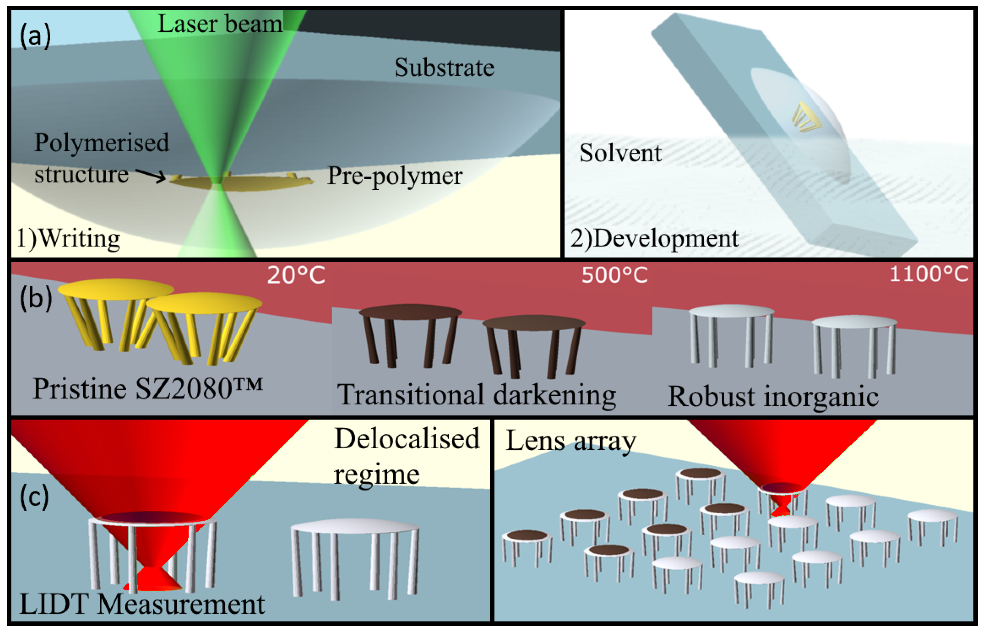
2. Fabrication
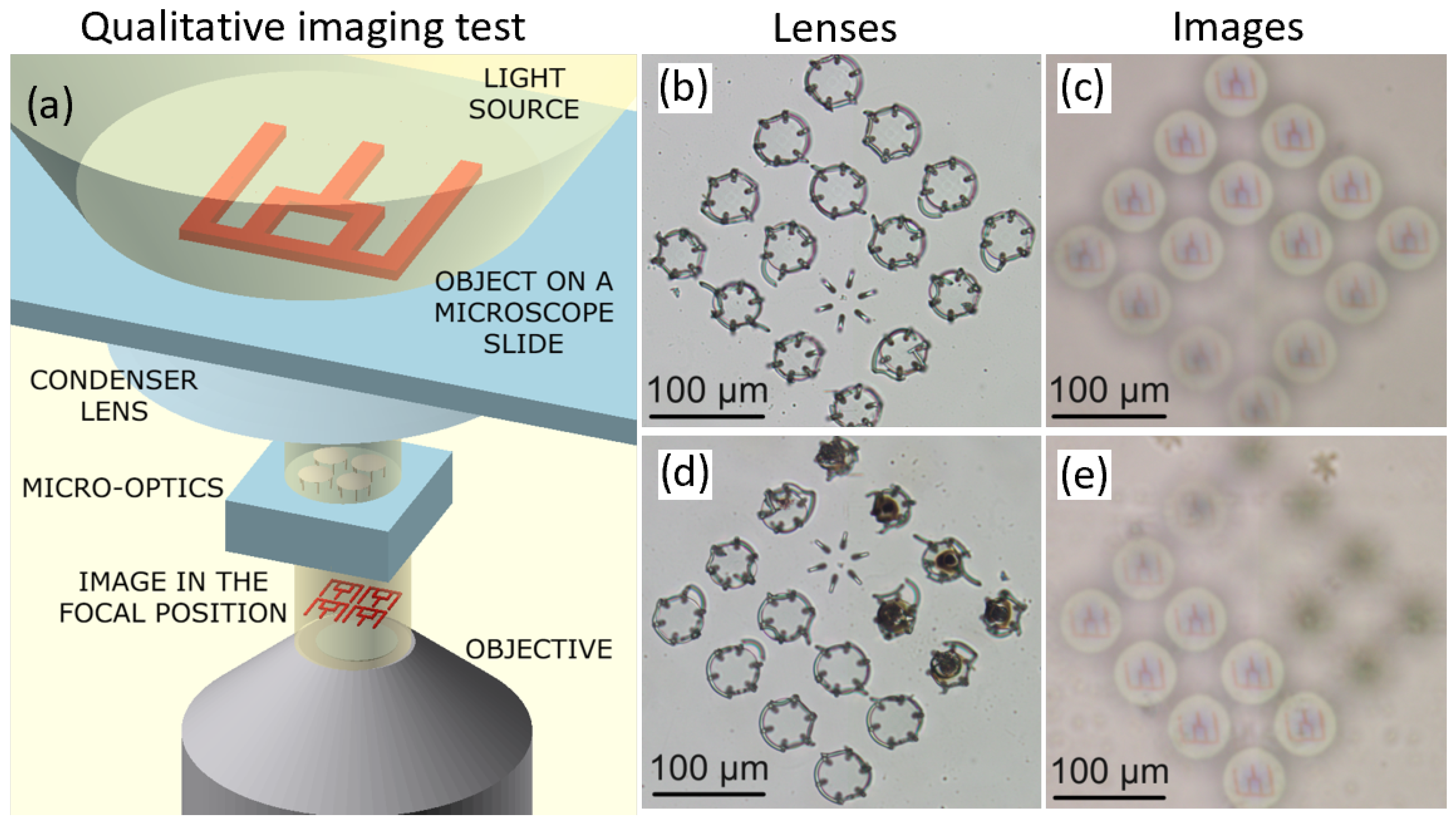
3. LIDT Metrology
4. Results
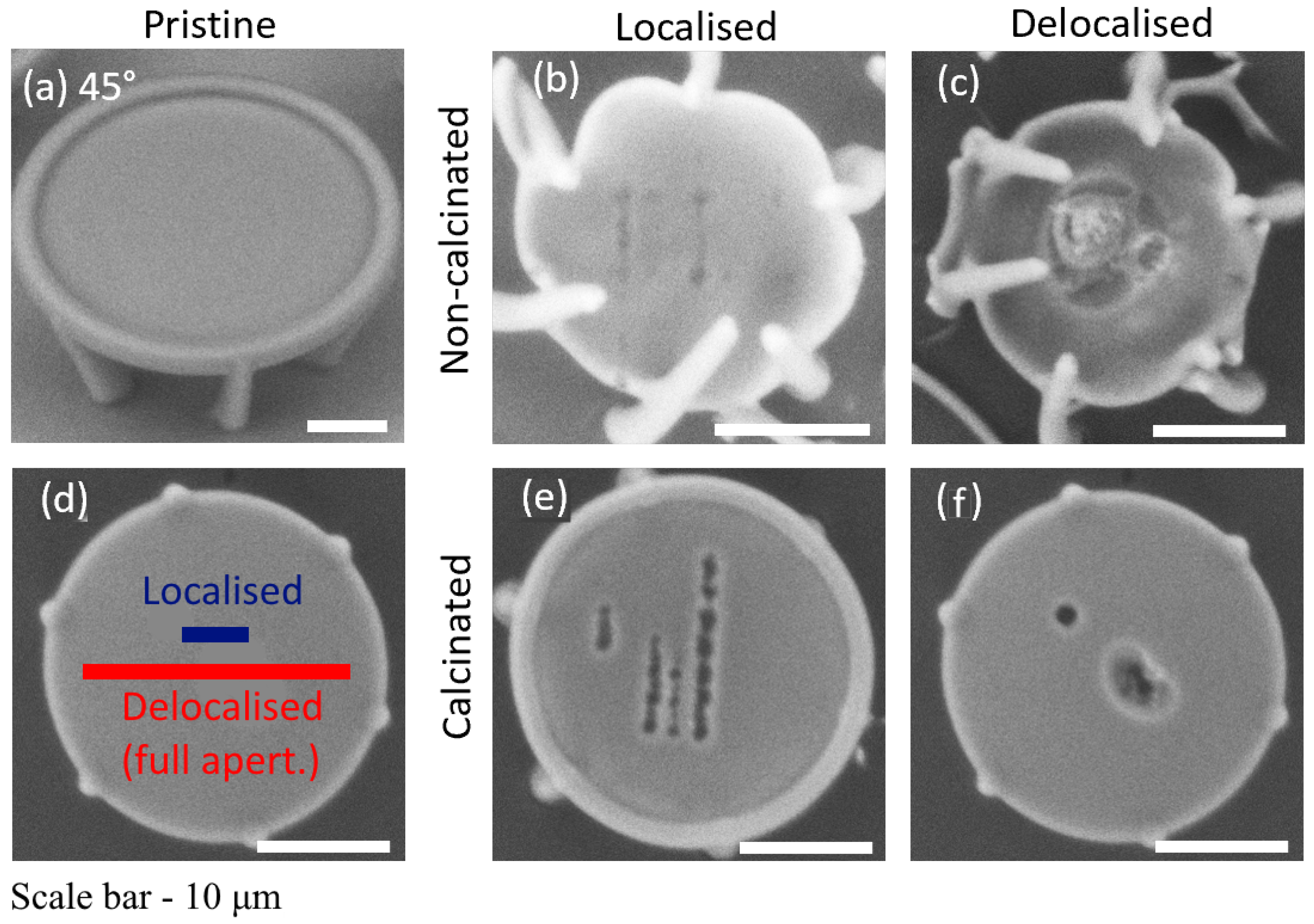
4.1. Morphology
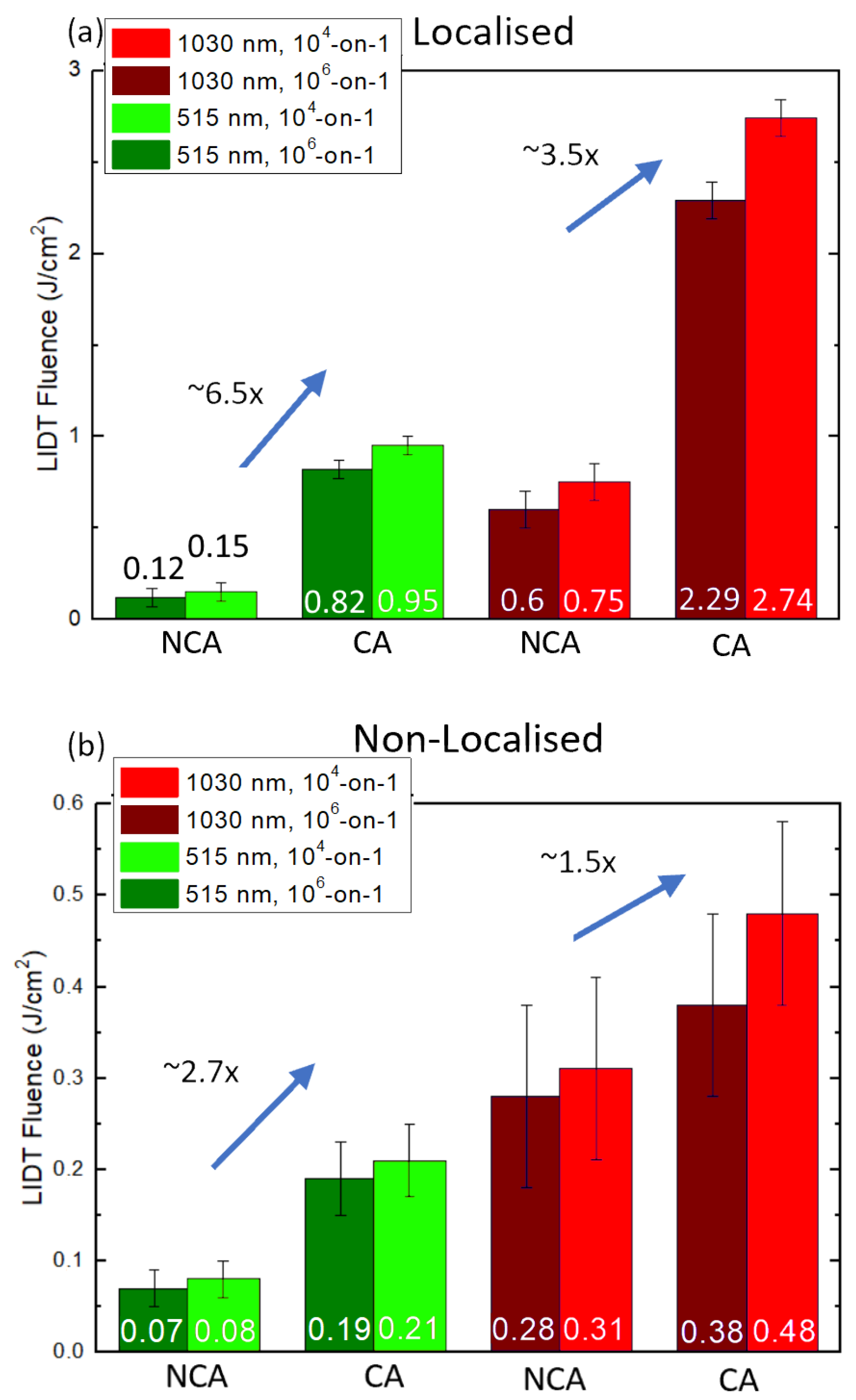
4.2. LIDT Values
5. Discussion
6. Conclusions
Author Contributions
Funding
Institutional Review Board Statement
Informed Consent Statement
Data Availability Statement
Acknowledgments
Conflicts of Interest
Abbreviations
| LIDT | Laser-Induced Damage Threshold |
| LDW | Laser Direct Writing |
| S-on-1 | Series-on-One |
| PI | Photo-Initiator |
| CA | Calcinated |
| NCA | Non-Calcinated |
| SEM | Scanning Electron Microscope |
References
- Wang, H.; Zhang, W.; Ladika, D.; Yu, H.; Gailevičius, D.; Wang, H.; Pan, C.; Nair, P.N.; Ke, Y.; Mori, T.; et al. Two-photon polymerization lithography for optics and Photonics: Fundamentals, materials, technologies, and applications. Adv. Funct. Mater. 2023, 2214211. [Google Scholar] [CrossRef]
- Gonzalez-Hernandez, D.; Varapnickas, S.; Bertoncini, A.; Liberale, C.; Malinauskas, M. Micro-Optics 3D printed via multi-photon laser lithography. Advanced Optical Materials 2022, 11, 2201701. [Google Scholar] [CrossRef]
- Wu, D.; Chen, Q.D.; Niu, L.G.; Jiao, J.; Xia, H.; Song, J.F.; Sun, H.B. 100% Fill-Factor Aspheric Microlens Arrays (AMLA) With Sub-20-nm Precision. IEEE Photonics Technol. Lett. 2009, 21, 1535–1537. [Google Scholar] [CrossRef]
- Asadollahbaik, A.; Thiele, S.; Weber, K.; Kumar, A.; Drozella, J.; Sterl, F.; Herkommer, A.M.; Giessen, H.; Fick, J. Highly Efficient Dual-Fiber Optical Trapping with 3D Printed Diffractive Fresnel Lenses. ACS Photonics 2020, 7, 88–97. [Google Scholar] [CrossRef]
- Sandford O’Neill, J.; Salter, P.; Zhao, Z.; Chen, B.; Daginawalla, H.; Booth, M.J.; Elston, S.J.; Morris, S.M. 3D Switchable Diffractive Optical Elements Fabricated with Two-Photon Polymerization. Adv. Opt. Mater. 2022, 10, 2102446. [Google Scholar] [CrossRef]
- Mu, H.; Smith, D.; Katkus, T.; Gailevičius, D.; Malinauskas, M.; Nishijima, Y.; Stoddart, P.R.; Ruan, D.; Ryu, M.; Morikawa, J.; et al. Polarisation control in arrays of Microlenses and gratings: Performance in visible–IR spectral ranges. Micromachines 2023, 14, 798. [Google Scholar] [CrossRef]
- Faniayeu, I.; Khakhomov, S.; Semchenko, I.; Mizeikis, V. Highly transparent twist polarizer metasurface. Appl. Phys. Lett. 2017, 111, 1–5. [Google Scholar] [CrossRef]
- Žukauskas, A.; Malinauskas, M.; Brasselet, E. Monolithic generators of pseudo-nondiffracting optical vortex beams at the microscale. Appl. Phys. Lett. 2013, 103, 181122. [Google Scholar] [CrossRef]
- Thiele, S.; Arzenbacher, K.; Gissibl, T.; Giessen, H.; Herkommer, A.M. 3D-printed eagle eye: Compound microlens system for foveated imaging. Sci. Adv. 2017, 3, e1602655. [Google Scholar] [CrossRef]
- Marini, M.; Nardini, A.; Martínez Vázquez, R.; Conci, C.; Bouzin, M.; Collini, M.; Osellame, R.; Cerullo, G.; Kariman, B.S.; Farsari, M.; et al. Microlenses fabricated by two-photon laser polymerization for cell imaging with non-linear excitation microscopy. Adv. Funct. Mater. 2023, 2213926. [Google Scholar] [CrossRef]
- Galvanauskas, K.; Astrauskyte, D.; Balcas, G.; Gailevičius, D.; Grineviciute, L.; Malinauskas, M. High-transparency 3D micro-optics of hybrid-polymer SZ2080™ made via Ultrafast Laser Nanolithography and atomic layer deposition. Opt. Open 2023, 104228. [Google Scholar] [CrossRef]
- Siegle, L.; Ristok, S.; Giessen, H. Complex aspherical singlet and Doublet Microoptics by Grayscale 3D printing. Opt. Express 2023, 31, 4179. [Google Scholar] [CrossRef]
- Gonzalez-Hernandez, D.; Sanchez-Padilla, B.; Gailevicius, D.; Chandran Thodika, S.; Brasselet, E.; Malinauskas, M. Single-step 3D printing of micro-optics with adjustable refractiveindex by ultrafast laser nanolithography. Adv. Opt. Mater. 2023, 2300258. [Google Scholar] [CrossRef]
- Gopinath, S.; Angamuthu, P.P.; Kahro, T.; Bleahu, A.; Arockiaraj, F.G.; Smith, D.; Ng, S.H.; Juodkazis, S.; Kukli, K.; Tamm, A.; et al. Implementation of a large-area diffractive lens using multiple sub-aperture diffractive lenses and computational reconstruction. Photonics 2022, 10, 3. [Google Scholar] [CrossRef]
- LaFratta, C.N.; Simoska, O.; Pelse, I.; Weng, S.; Ingram, M. A convenient direct laser writing system for the creation of Microfluidic Masters. Microfluid. Nanofluid. 2015, 19, 419–426. [Google Scholar] [CrossRef]
- Hu, Y.; Miles, B.T.; Ho, Y.L.D.; Taverne, M.P.; Chen, L.; Gersen, H.; Rarity, J.G.; Faul, C.F. Toward direct laser writing of actively tuneable 3D photonic crystals. Adv. Opt. Mater. 2016, 5, 1600458. [Google Scholar] [CrossRef]
- Fischer, J.; Wegener, M. Three-dimensional optical laser lithography beyond the diffraction limit. Laser Photonics Rev. 2012, 7, 22–44. [Google Scholar] [CrossRef]
- Vyatskikh, A.; Ng, R.C.; Edwards, B.; Briggs, R.M.; Greer, J.R. Additive manufacturing of high-refractive-index, nanoarchitected titanium dioxide for 3D dielectric photonic crystals. Nano Lett. 2020, 20, 3513–3520. [Google Scholar] [CrossRef] [PubMed]
- Hong, Z.; Ye, P.; Loy, D.A.; Liang, R. High-precision printing of complex glass imaging optics with precondensed liquid silica resin. Adv. Sci. 2022, 9, 2105595. [Google Scholar] [CrossRef]
- Hong, Z.; Ye, P.; Loy, D.A.; Liang, R. Three-dimensional printing of glass micro-optics. Optica 2021, 8, 904. [Google Scholar] [CrossRef]
- ISO 21254-2:2011; Lasers and Laser-Related Equipment—Test Methods for Laser-Induced Damage Threshold. International Organization for Standardization: Geneva, Switzerland, 2011.
- Stankova, N.; Atanasov, P.; Nikov, R.; Nikov, R.; Nedyalkov, N.; Stoyanchov, T.; Fukata, N.; Kolev, K.; Valova, E.; Georgieva, J.; et al. Optical properties of polydimethylsiloxane (PDMS) during nanosecond laser processing. Appl. Surf. Sci. 2016, 374, 96–103. [Google Scholar] [CrossRef]
- Saha, S.K.; Divin, C.; Cuadra, J.A.; Panas, R.M. Effect of proximity of features on the damage threshold during submicron additive manufacturing via two-photon polymerization. J. Micro-Nano-Manuf. 2017, 5, 031002. [Google Scholar] [CrossRef]
- Žukauskas, A.; Batavičiūtė, G.; Ščiuka, M.; Jukna, T.; Melninkaitis, A.; Malinauskas, M. Characterization of photopolymers used in laser 3D micro/nanolithography by means of laser-induced damage threshold (LIDT). Opt. Mater. Express 2014, 4, 1601. [Google Scholar] [CrossRef]
- Žukauskas, A.; Batavičiūtė, G.; Ščiuka, M.; Balevičius, Z.; Melninkaitis, A.; Malinauskas, M. Effect of the photoinitiator presence and exposure conditions on laser-induced damage threshold of ORMOSIL (SZ2080). Opt. Mater. 2015, 39, 224–231. [Google Scholar] [CrossRef]
- Gallais, L.; Commandré, M. Laser-induced damage thresholds of bulk and coating optical materials at 1030 nm, 500 fs. Appl. Opt. 2014, 53, A186. [Google Scholar] [CrossRef]
- Butkutė, A.; Čekanavičius, L.; Rimšelis, G.; Gailevičius, D.; Mizeikis, V.; Melninkaitis, A.; Baldacchini, T.; Jonušauskas, L.; Malinauskas, M. Optical damage thresholds of microstructures made by laser three-dimensional nanolithography. Opt. Lett. 2020, 45, 13–16. [Google Scholar] [CrossRef]
- Simakov, E.; Gilbertson, R.; Herman, M.; Pilania, G.; Shchegolkov, D.; Walker, E.; England, R.; Wootton, K. Possibilities for Fabricating Polymer Dielectric Laser Accelerator Structures with Additive Manufacturing. In Proceedings of the 9th International Particle Accelerator Conference, Vancouver, BC, Canada, 29 April–4 May 2018; pp. 9–12. [Google Scholar] [CrossRef]
- Samsonas, D.; Skliutas, E.; Ciburys, A.; Kontenis, L.; Gailevičius, D.; Berzinš, J.; Narbutis, D.; Jukna, V.; Vengris, M.; Juodkazis, S.; et al. 3D nanopolymerization and damage threshold dependence on laser wavelength and pulse duration. Nanophotonics 2023, 12. [Google Scholar] [CrossRef]
- Kabouraki, E.; Melissinaki, V.; Yadav, A.; Melninkaitis, A.; Tourlouki, K.; Tachtsidis, T.; Kehagias, N.; Barmparis, G.D.; Papazoglou, D.G.; Rafailov, E.; et al. High laser induced damage threshold photoresists for nano-imprint and 3D multi-photon lithography. Nanophotonics 2021, 10, 3759–3768. [Google Scholar] [CrossRef]
- Merkininkaitė, G.; Aleksandravičius, E.; Malinauskas, M.; Gailevičius, D.; Šakirzanovas, S. Laser additive manufacturing of SiZrO2 tunable crystalline phase 3D nanostructures. Opto-Electr. Adv. 2022, 5, 210077. [Google Scholar] [CrossRef]
- Ovsianikov, A.; Viertl, J.; Chichkov, B.; Oubaha, M.; MacCraith, B.; Sakellari, I.; Giakoumaki, A.; Gray, D.; Vamvakaki, M.; Farsari, M.; et al. Ultra-Low Shrinkage Hybrid Photosensitive Material for Two-Photon Polymerization Microfabrication. ACS Nano 2008, 2, 2257–2262. [Google Scholar] [CrossRef]
- Gonzalez-Hernandez, D.; Varapnickas, S.; Merkininkaitė, G.; Čiburys, A.; Gailevičius, D.; Šakirzanovas, S.; Juodkazis, S.; Malinauskas, M. Laser 3D Printing of Inorganic Free-Form Micro-Optics. Photonics 2021, 8, 577. [Google Scholar] [CrossRef]
- Merkinaite, G.; Gailevicius, D.; Staisiunas, L.; Ezerskyte, E.; Vargalis, R.; Malinauskas, M.; Sakirzanovas, S. Additive Manufacturing of Extremely Hard SiOC Ceramic 3D Micro-Structures. Adv. Eng. Mater. 2023, in press. [Google Scholar]
- Butkus, A.; Skliutas, E.; Gailevičius, D.; Malinauskas, M. Femtosecond-laser direct writing 3D micro/nano-lithography using VIS-light oscillator. J. Cent. South Univ. 2022, 29, 3270–3276. [Google Scholar] [CrossRef]
- Garrison, B.J.; Srinivasan, R. Laser ablation of organic polymers: Microscopic models for photochemical and thermal processes. J. Appl. Phys. 1985, 57, 2909–2914. [Google Scholar] [CrossRef]
- Jonusauskas, L.; Gailevicius, D.; Mikoliunaite, L.; Sakalauskas, D.; Šakirzanovas, S.; Juodkazis, S.; Malinauskas, M. Optically clear and resilient free-form u-optics 3D-printed via Ultrafast Laser Lithography. Materials 2017, 10, 12. [Google Scholar] [CrossRef]
- Vlassov, S.; Oras, S.; Timusk, M.; Zadin, V.; Tiirats, T.; Sosnin, I.M.; Lõhmus, R.; Linarts, A.; Kyritsakis, A.; Dorogin, L.M.; et al. Thermal, mechanical, and acoustic properties of polydimethylsiloxane filled with hollow glass microspheres. Materials 2022, 15, 1652. [Google Scholar] [CrossRef]
- OrmoComp®. Available online: https://www.microresist.de/en/produkt/ormocomp/ (accessed on 24 April 2023).
- Chang, C.H.; Lin, C.Y.; Chang, C.H.; Liu, F.H.; Huang, Y.T.; Liao, Y.S. Enhanced biomedical applicability of zro2–sio2 ceramic composites in 3D printed bone scaffolds. Sci. Rep. 2022, 12, 6845. [Google Scholar] [CrossRef]
- Barkaline, V.V.; Nelayev, V.V.; Chashinski, A.S. SIO2 on CNT: Molecular dynamics simulation. SPIE Proc. 2006, 6253, 57–64. [Google Scholar] [CrossRef]
- Smalakys, L.; Melninkaitis, A. Predicting lifetime of optical components with bayesian inference. Opt. Express 2021, 29, 903. [Google Scholar] [CrossRef]
- Ward, J.M.; Yang, Y.; Nic Chormaic, S. Glass-on-glass fabrication of bottle-shaped tunable microlasers and their applications. Sci. Rep. 2016, 6, 25152. [Google Scholar] [CrossRef]
- Balcas, G.; Malinauskas, F.; Maria, G.; Juodkazis, S. Fabrication of glass-ceramic 3D micro-optics by combining laser lithography and calcination. Adv. Funct. Mater. 2023, 2215230. [Google Scholar] [CrossRef]


Disclaimer/Publisher’s Note: The statements, opinions and data contained in all publications are solely those of the individual author(s) and contributor(s) and not of MDPI and/or the editor(s). MDPI and/or the editor(s) disclaim responsibility for any injury to people or property resulting from any ideas, methods, instructions or products referred to in the content. |
© 2023 by the authors. Licensee MDPI, Basel, Switzerland. This article is an open access article distributed under the terms and conditions of the Creative Commons Attribution (CC BY) license (https://creativecommons.org/licenses/by/4.0/).
Share and Cite
Gailevicius, D.; Zvirblis, R.; Galvanauskas, K.; Bataviciute, G.; Malinauskas, M. Calcination-Enhanced Laser-Induced Damage Threshold of 3D Micro-Optics Made with Laser Multi-Photon Lithography. Photonics 2023, 10, 597. https://doi.org/10.3390/photonics10050597
Gailevicius D, Zvirblis R, Galvanauskas K, Bataviciute G, Malinauskas M. Calcination-Enhanced Laser-Induced Damage Threshold of 3D Micro-Optics Made with Laser Multi-Photon Lithography. Photonics. 2023; 10(5):597. https://doi.org/10.3390/photonics10050597
Chicago/Turabian StyleGailevicius, Darius, Rokas Zvirblis, Karolis Galvanauskas, Gintare Bataviciute, and Mangirdas Malinauskas. 2023. "Calcination-Enhanced Laser-Induced Damage Threshold of 3D Micro-Optics Made with Laser Multi-Photon Lithography" Photonics 10, no. 5: 597. https://doi.org/10.3390/photonics10050597