1. Introduction
With the development of intelligent manufacturing, there are a large number of specular components in the fields of aerospace, the automotive industry, high-speed trains, and so on [
1,
2,
3,
4]. It is of great significance to obtain three-dimensional (3D) data accurately to improve their performance. Phase measuring deflectometry (PMD) has been widely studied and applied because of its advantages of being non-contact, having a large dynamic range, and its high-precision and fast-acquisition [
5,
6,
7,
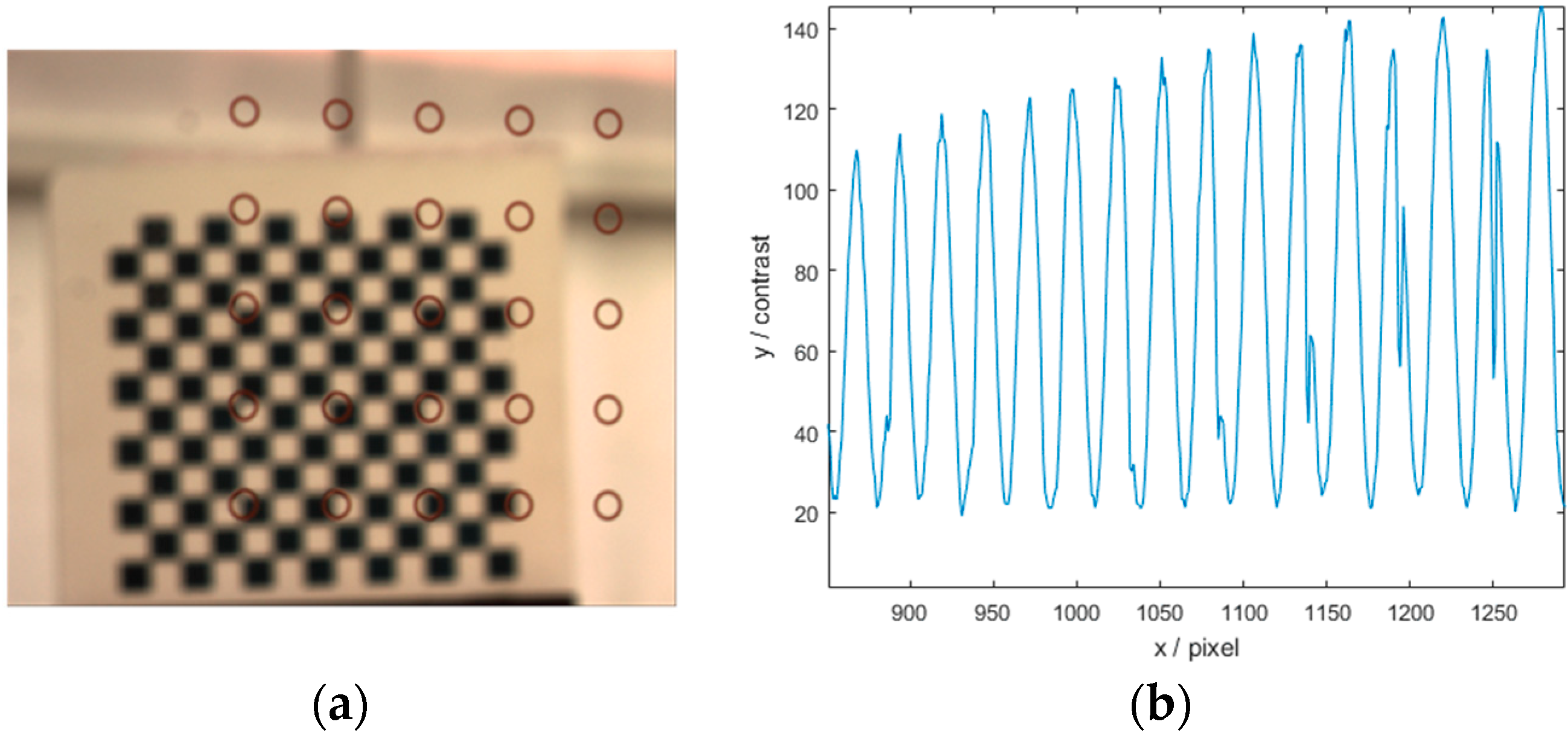
8]. The charged couple device (CCD), surface under test (SUT), and liquid crystal display (LCD) of the classical PMD systems are in triangulation relation. The virtual image of the LCD screen reflected by the SUT falls beyond the depth of field (DOF) of the camera lens. Due to the limited DOF of the camera lens, the SUT and the coded image reflected by the SUT cannot be clearly imaged together. Therefore, the obtained images are defocusing. This problem introduces errors for corner extraction and the reduced contrast of fringe, as shown in
Figure 1. Ultimately, the accuracy of 3D shape data is affected.
In order to solve the limited DOF of the camera lens, many methods have been studied. Su et al. [
9] presented a phase measuring profilometry (PMP) method in which a defocused image of the projected square-wave Ronchi grating, and a phase shifting technique, were chosen for optical phase evaluation. They drew the conclusion, through simulation experiments, that the phase error caused by the odd number of phase shifts is small, which established the theoretical foundation for the binary fringe defocusing technique study. The introduction of binary fringes has largely compensated for the influence of the limited DOF of the camera lens. Lei et al. [
10,
11,
12] compared the potential errors for defocusing binary patterns (DBP) and focusing sinusoidal patterns (FSP) and proposed approximating the sinusoidal fringes by a defocused Ronchi-like binary pattern. The degree of defocusing was modeled by the breadth of the point-spread function of the system. Niu et al. [
13] proposed an advanced PMD method by using a bi-telecentric lens. They built up the direct relationship between depth and absolute phase after calibrating and realized the measurement of complex specular objects with discontinuous surfaces. Shi et al. [
14] proposed a new infrared PMD based on the defocused binary fringe that combined a binary fringe defocusing technique and direct PMD (DPMD). This method decreased the influence of the limited DOF of the camera lens on measurements in the PMD system effectively. However, none of the methods can fundamentally solve the limited DOF of the camera lens on the measurement system. The system based on a bi-telecentric lens is difficult to calibrate and the measurement angle of view is limited. Moreover, most methods compensate for the effect of the DOF through a defocusing technique, but it is difficult to determine the defocusing distance of the system effectively.
In order to clearly image the SUT and the fringe patterns reflected by the SUT, this paper proposes an aided imaging phase measuring deflectometry (AIPMD) based on a concave focusing mirror. By virtue of the principle of paraxial reflection imaging of concave mirror, this method changes the imaging reflection optical path, and realizes the clear imaging of the encoded patterns and the SUT in the DOF of the camera lens simultaneously. Meanwhile, the iterative coefficient specular reconstruction algorithm is studied based on this system, and the relationship between the phase and the depth change of the SUT is established to achieve a high-precision measurement of non-continuous specular objects.
The remainder of this paper is organized as follows.
Section 2 introduces the principle of the proposed AIPMD method.
Section 3 provides experiments and results to verify the feasibility and accuracy of the proposed method.
Section 4 draws a conclusion and gives future work.
2. Principle and Methods
2.1. AIPMD Based on Concave Focusing Mirror
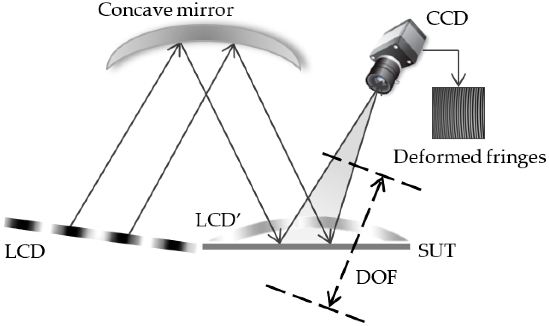
The schematic diagram of the proposed method is illustrated in
Figure 2, which consists of an LCD, a concave mirror, and a CCD camera. The concave mirror is fixed on an optical table vertically. The LCD is fixed at the position of twice focal length on one side of the optical axis of the concave mirror and is also fixed vertically to the optical table. The real image of the LCD is labeled as LCD’, which is reflected by the concave mirror. It falls at the position of twice focal length on the other side of the optical axis of the concave mirror, where the SUT is placed. When the positions of the LCD and the concave mirror remain fixed, the LCD’ no longer changes. The CCD is fixed on the optical table, and the optical axis of the CCD is parallel to the optical table. The CCD, the SUT, and the concave mirror are in triangulation relation. The DOF of the camera is adjusted to focus on the SUT. The LCD’, the SUT, and the CCD form a PMD system. In this system, the LCD’ is regarded as a display screen. The image formed by the LCD’ reflected by the SUT is labeled as LCD”. Differing from the traditional PMD system, the LCD’ is close to the SUT infinitely, and LCD” and the SUT can be clearly imaged in the DOF of the CCD simultaneously. Therefore, the newly formed PMD system effectively avoids defocusing introduced by the inherent limitation of the DOF of the camera.
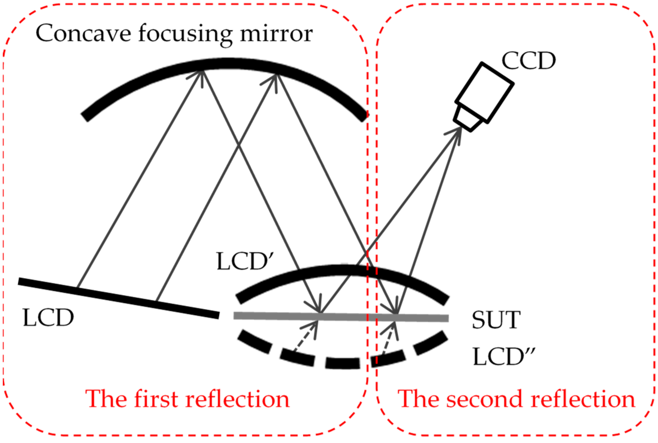
The entire experimental system can be regarded as a process of twice reflection imaging, as shown in
Figure 3. The process of LCD reflection to LCD’ by the concave mirror is the first reflection, which is regarded as the aided reflection imaging part of the system. The second reflection is the process of measuring the SUT by using the LCD’ formed by the first reflection. During the measuring process, the phase on the LCD’ is taken as the reference phase. The encoded fringe patterns on the LCD’ screen are modulated by the SUT and the deformed fringes LCD” are captured by the camera.
2.2. Mathematic Model and Calibration
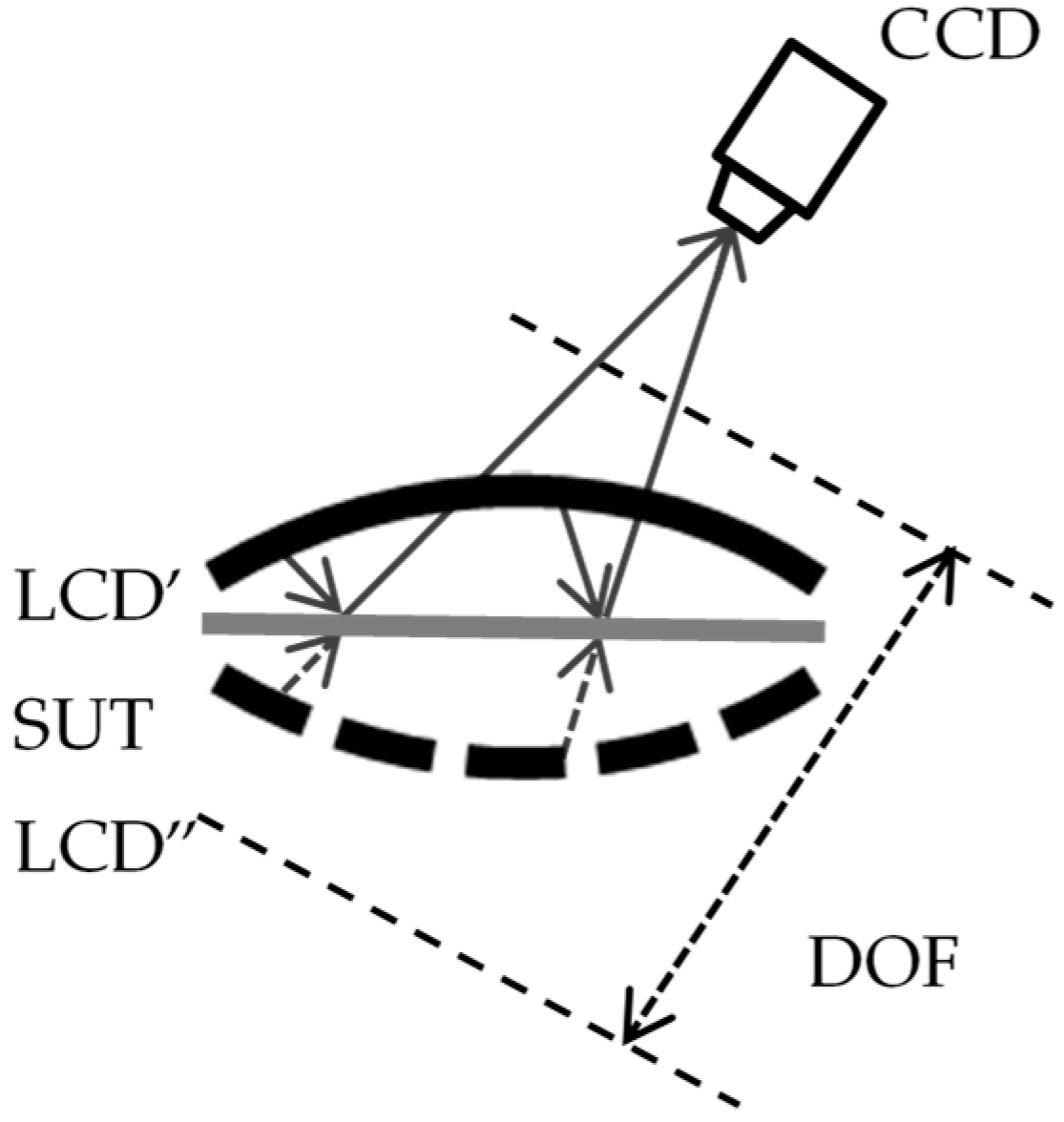
During the process of establishing a mathematical model of the system, the first reflection-aided reflection imaging part is no longer considered, as shown in
Figure 4. When the height of the SUT changes, the reflected phase of the SUT collected by the camera changes. The relationship between the surface height
and the phase captured by the camera
can be established:
where
is the pixel coordinates of the imaging target plane,
is the phase acquired by the camera,
is the specular height information of the SUT,
is the relation coefficient between
and
. The measurement is the process of solving the height information
of the SUT. Phase information
of the SUT can be obtained by multi-step phase-shifting algorithm and the optimal three frequency selection method [
15,
16,
17]. Therefore, 3D reconstruction of the SUT can be realized by obtaining coefficient matrix
between the phase at each position and the height of the specular surface.
The calibration process of the system is how to solve the coefficient matrix
. According to Equation (1), it can be seen that at least (
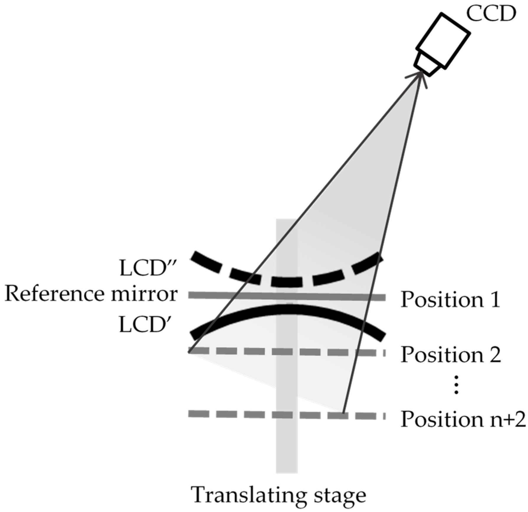
n + 2) sets of calibration data need to be solved. The system calibration is realized by a high-precision translating stage and a flat mirror. The process of system calibration is to calibrate the relationship between the surface height
of the SUT and the phase
. The calibration diagram is shown in
Figure 5. The high-precision translating stage is fixed on the optical table parallel to the optical axis of the concave mirror along the LCD’ imaging direction. The flat mirror is regarded as a reference mirror and fixed on the translating stage vertically. By adjusting the deflection angle of the reference mirror, the camera can receive the image LCD” reflected by the reference mirror. The reference mirror at the same plane position of the LCD is defined as the reference position. During the calibration process, the translating stage is controlled to move the reference mirror (
n + 2) positions in the DOF of the camera with a fixed step length along the same direction. The LCD displays the fringe patterns that conform to the eight-step phase-shifting algorithm and the optimal three frequency selection method. The camera collects the fringe patterns reflected by the reference mirror at different positions. The wrapped phase is obtained by the eight-step phase-shifting algorithm, and the absolute phase is obtained by the optimal three frequency selection method. At the same time, the height of the reference mirror moving by the translating stage is known, and the height
and phase
of different positions are combined. The coefficient matrix
can be obtained by fitting the simultaneous equation:
where
is absolute phase of the reference position, and
is height of the reference position.
,
,…,
,
,…,
are heights of different calibration positions relative to the reference position.
,
,…,
,
,…,
are absolute phases corresponding to each position.
3. Experiments and Results
3.1. Calibration
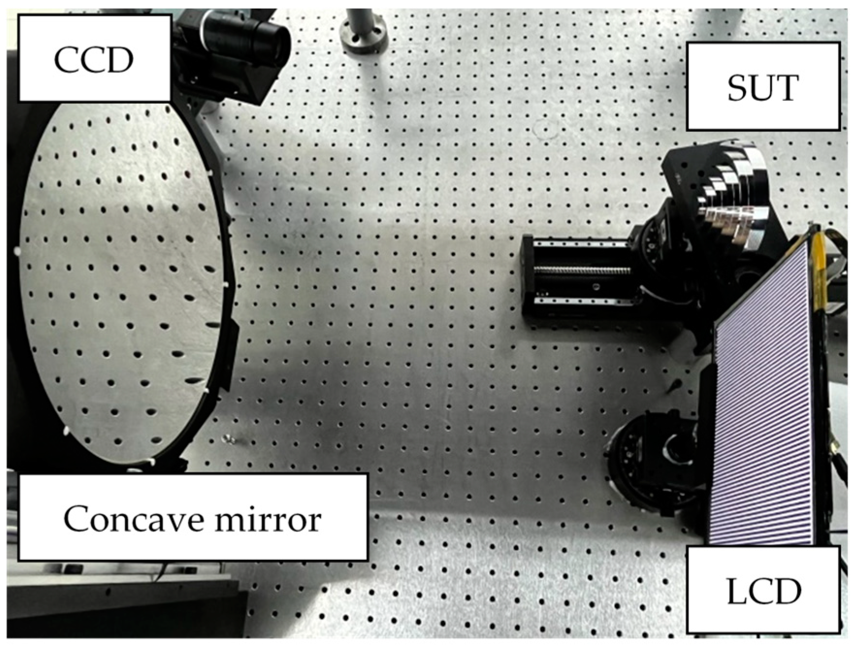
The developed AIPMD system consists of an LCD, a concave mirror, and a CCD camera. The hardware diagram of the system is shown in
Figure 6. According to the requirements of system working distance and field of view, the camera is an XIQ series MQ042RG-CM ultra-compact low-power camera produced by XIMEA Company in Germany. Its resolution is 2048 × 2048 pixels, and the frame rate is 90 fps. The camera lens is a 22 mm manual focus lens and the aperture range is F/2.0–32. The resolution of the LCD is 1536 × 2048 pixels, and its pixel size is 0.096 × 0.096 mm. The radius of curvature of the concave mirror is 500 mm, which is determined by the optimal working distance of the system.
During calibration, the reference mirror is a flat mirror and the resolution of the translating stage is 1 µm. The translating stage was controlled to move the reference mirror from a distance of +12 mm to a distance of −12 mm with regard to the reference position with a step length of 2 mm, and a total of 13 positions were moved in the process. The reference position was labeled as position 13. At the same time, the height of the reference mirror at each position from position 13 and the corresponding absolute phase value were recorded. By combining the depth value and phase information of each position, the relationship can be obtained. The coefficient matrix
can be obtained by six-order fitting:
3.2. Experiments
In order to verify the accuracy and stability of the proposed AIPMD method, 3D data of the specular plane depth information at any position in the system, the concave mirror, and the steps were measured.
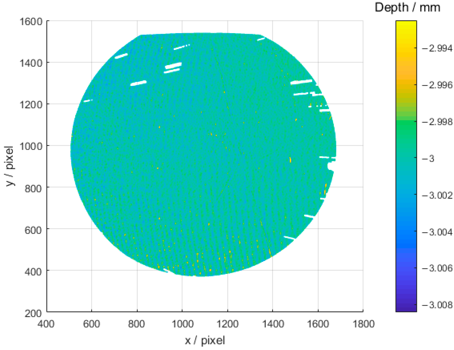
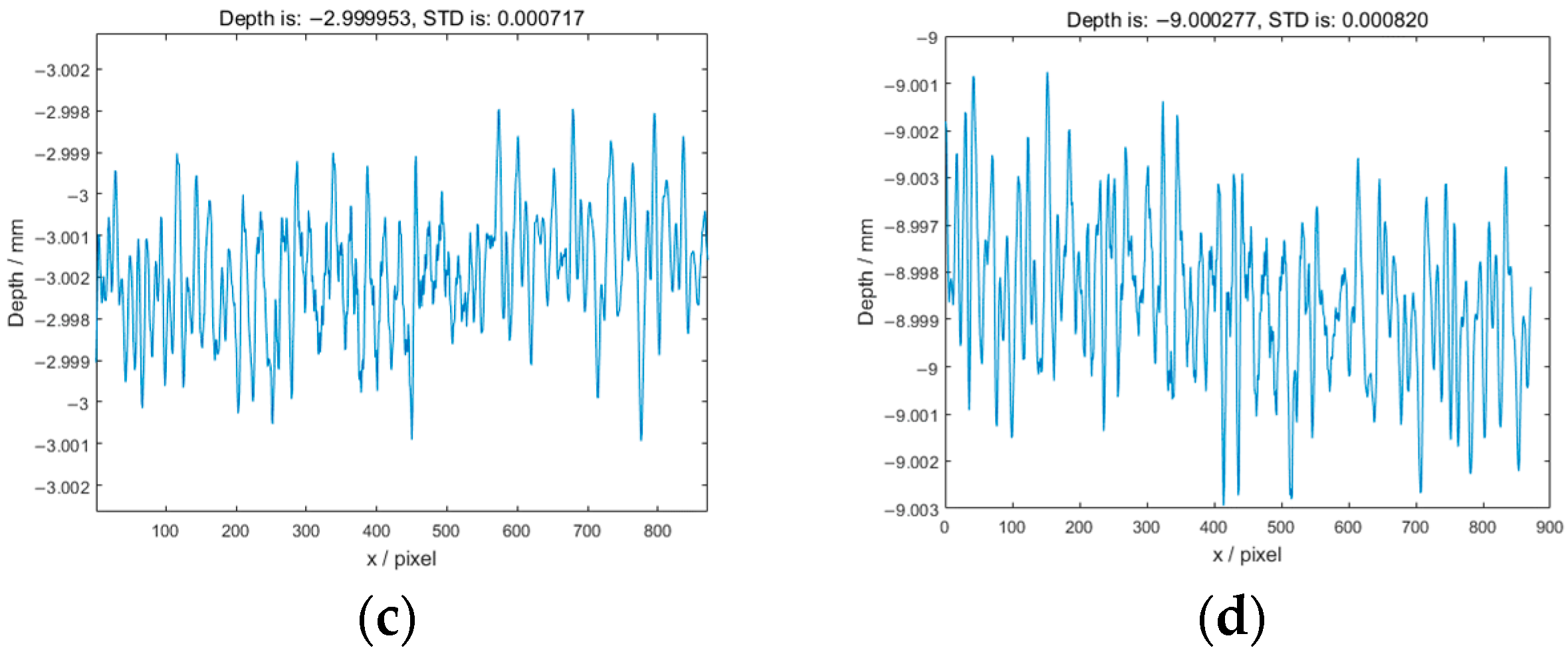
Firstly, 3D data of the reference mirror controlled by the translating stage was reconstructed to verify the accuracy. The moving distance of the translating stage was +11 mm, +5 mm, −3 mm, and −9 mm. The 3D reconstruction results at the moving distance of −3 mm are shown in
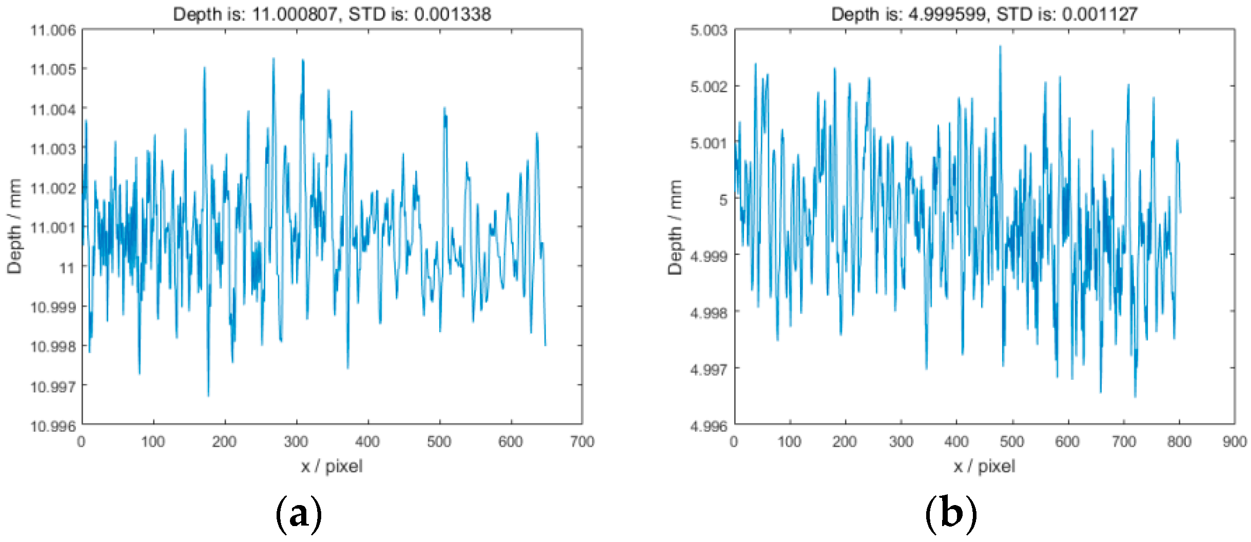
Figure 7. The reconstruction accuracy and standard deviation (STD) at each moving position are shown in
Figure 8a–d. According to the specular plane reconstruction results, the reconstruction absolute error of the proposed method can reach 4.7 × 10
−5 mm, and the STD can reach 7.07 × 10
−4 mm.
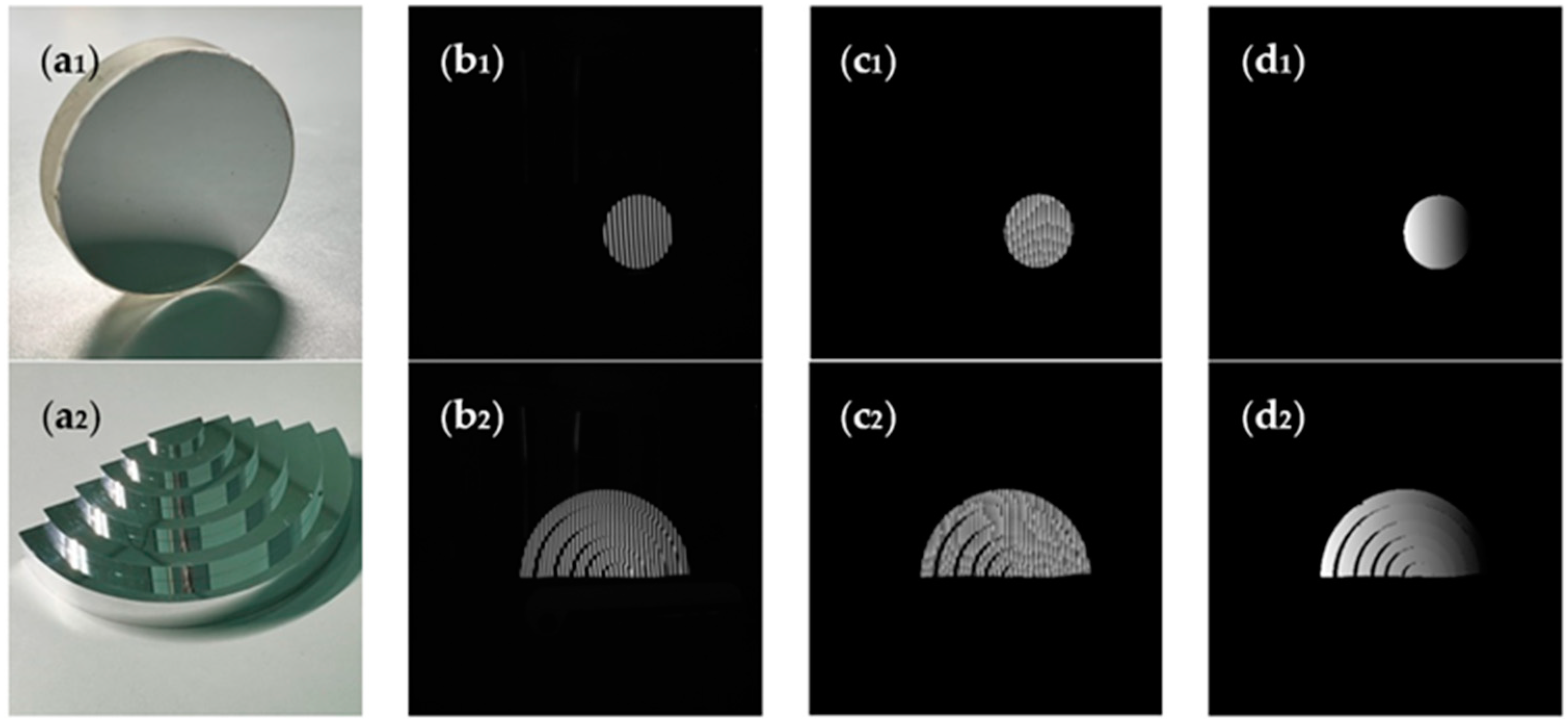
As shown in
Figure 9, (a1)–(a2) are the specular SUT: concave mirror and steps. (b1)–(b2) are the deformed fringes collected by the camera. (c1)–(c2) are the wrapped phase of the SUT obtained by the eight-step phase-shifting algorithm. (d1)–(d2) are the absolute phase of the SUT obtained by the optimal three frequency selection method.
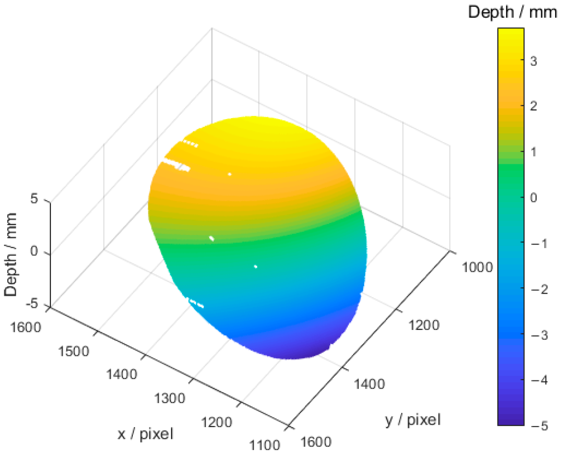
Figure 10 shows 3D data of the final reconstructed concave mirror by using the calibration coefficient matrix. At present, there are missing data in the reconstruction results. This is because the proposed system has not yet conducted error analysis, and values with large errors have been directly eliminated to obtain higher accuracy reconstruction results.
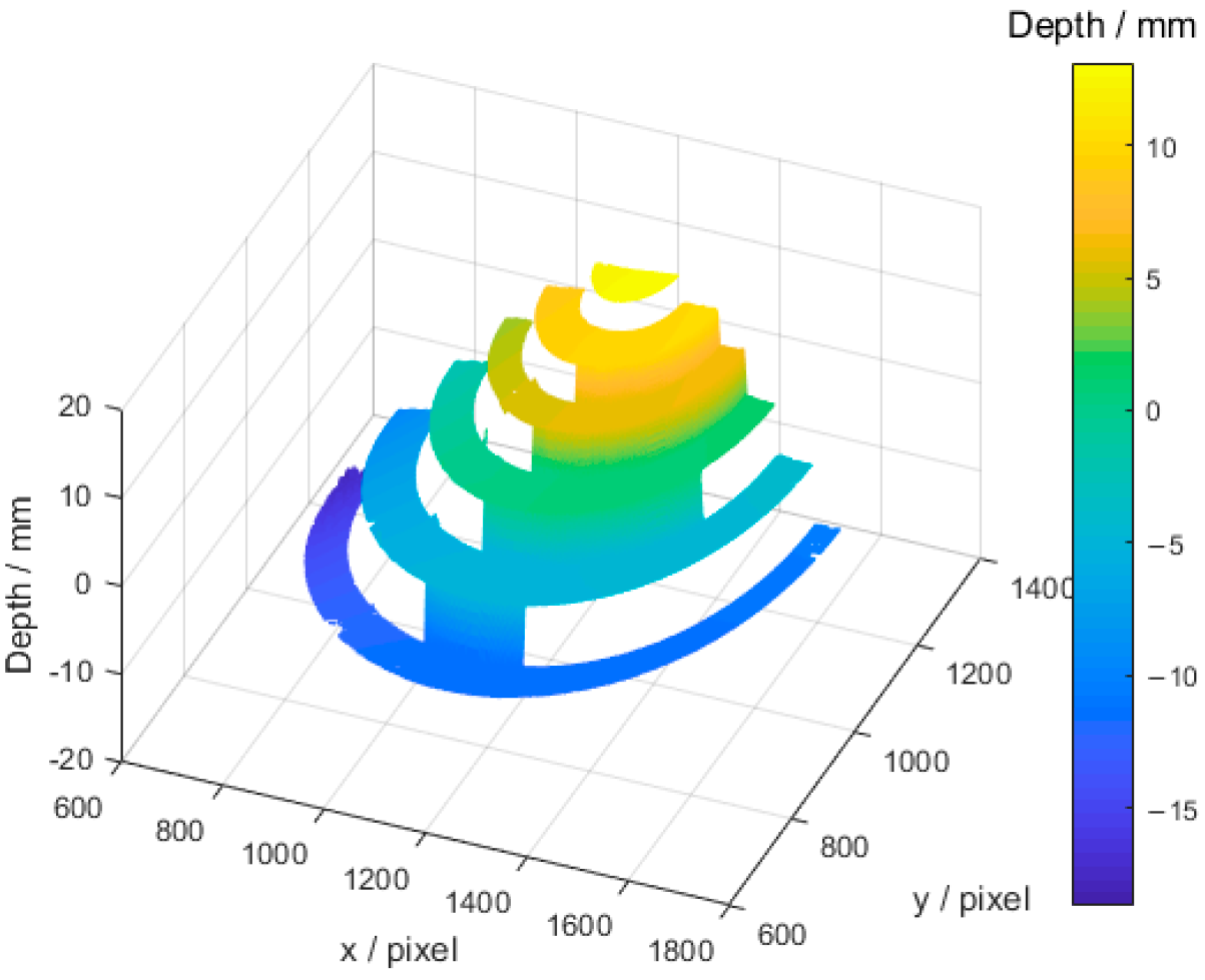
3D reconstruction data of the steps is shown in
Figure 11. To quantitatively evaluate the accuracy of the proposed method, the distances between adjacent steps were estimated. The comparative distances between the adjacent steps were measured by a C32-bit ZEISS Calypso coordinate measuring machine (CMM), and the data measured by CMM are taken as actual distance. In the process of measuring with the proposed method, the points on each step surface were fitted into a plane, and the distance between two adjacent fitting planes was calculated as the measured value. The results obtained by the proposed method were compared with the classical measurement method of the discontinuous mirror surface (Direct PMD, DPMD) [
17,
18], as shown in
Table 1.
The experimental results show that the proposed method can directly reconstruct 3D data of specular objects with high accuracy and reliability.
4. Discussion
PMD has been widely studied and applied due to its advantages of being non-contact, its large dynamic range, its high-precision, and its fast-acquisition. However, the inherent DOF limitation of the camera lens will introduce the reduced contrast of fringes and the inaccuracy of corner extraction in the existing PMD, which will affect the measurement accuracy. Through the experimental study, we find that the introduction of a concave mirror into the PMD system can effectively avoid the defocus of the LCD or calibration plate caused by the limitation of DOF of the camera lens and improve the measurement depth range of the system.
The feasibility of the proposed method is verified by conducting qualitative experiments on 3D reconstructions of the concave mirror and mirror planes. The accuracy of the proposed method is verified by conducting quantitative experiments on 3D reconstructions of the mirror planes and steps with known heights and the minimum measurement error of the proposed method for planar mirrors can reach 4.7 × 10⁻⁵ mm, and STD can reach 7.07 × 10⁻⁴ mm. Comparative experiments are conducted to compare the measurement accuracy with the original non-continuous specular object measurement method, resulting in a 63% improvement in measurement results. However, based on the proposed system, the secondary reflection process will introduce more noise and bring random errors to the system. In subsequent work, we will also analyze the error effects of LCD nonlinearity, concave mirror reflection, and camera gamma effect on the system, and analyze the sources of random errors in secondary reflection to obtain better measurement results. Above all, although the proposed method is currently affected by noise during the secondary reflection process, it cannot be ignored that this method directly achieves clear imaging of the image of LCD and SUT in DOF of the camera lens simultaneously, without any software adjustment and control, which greatly improves the fringe contrast and the measurement accuracy of the system.
5. Conclusions
This paper proposes an AIPMD method based on a concave focusing mirror. By virtue of the principle of paraxial reflection imaging of concave mirrors, this method effectively avoids the influence of the limited DOF of the camera lens on the measurement in the specular measurement system. The proposed method studies the iterative coefficient specular reconstruction algorithm, establishes the relationship between the phase and the depth change of the SUT, and realizes the high-precision measurement of the discontinuous specular objects. The accuracy and stability of the proposed method are verified by experiments on measuring specular surfaces. In the future, the system errors will be analyzed and more experiments will be conducted to adapt to the measurement requirements of more specular components with high precision.


