Polarization-Insensitive, Orthogonal Linearly Polarized and Orthogonal Circularly Polarized Synthetic Aperture Metalenses


Abstract
:1. Introduction
2. Materials and Methods
2.1. Design of Metalens
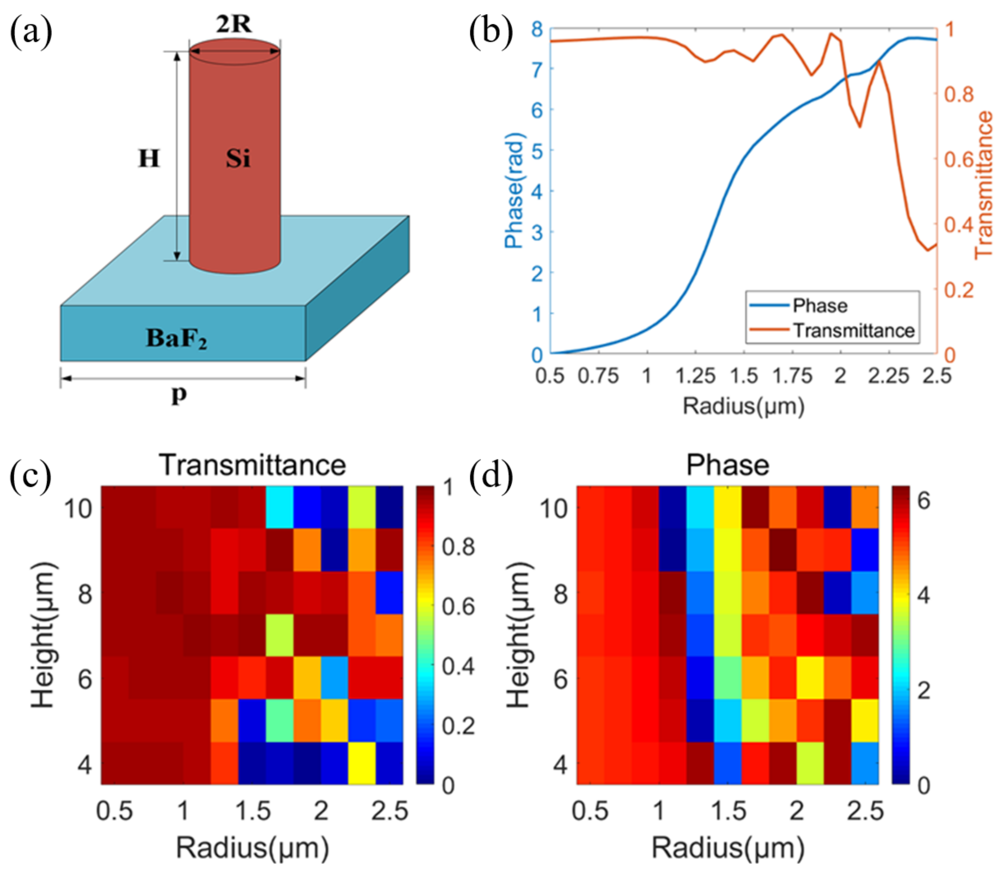
2.1.1. Design of the Polarization-Insensitive Metalens
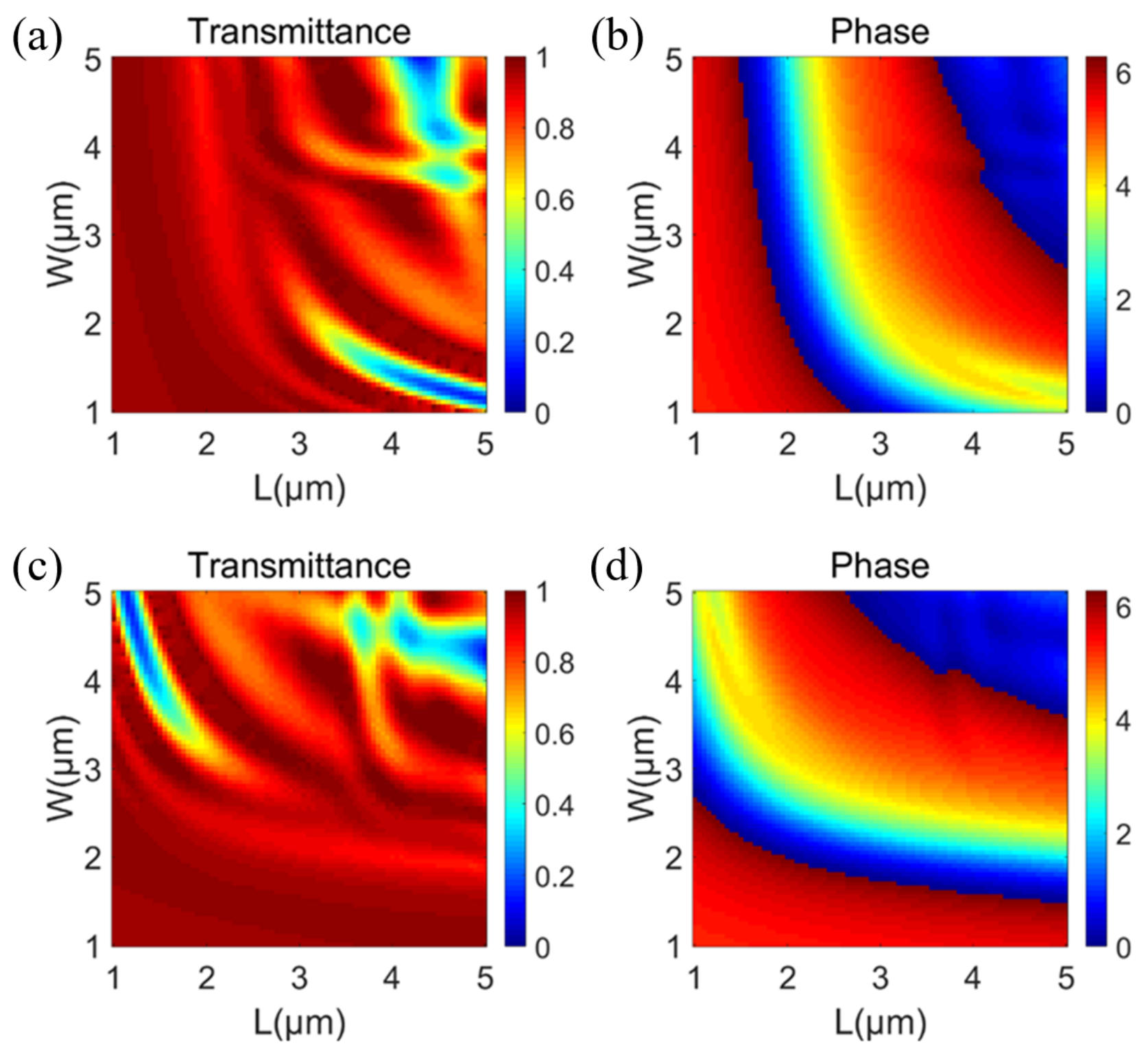
2.1.2. Design of the Orthogonal Linearly Polarized Metalens
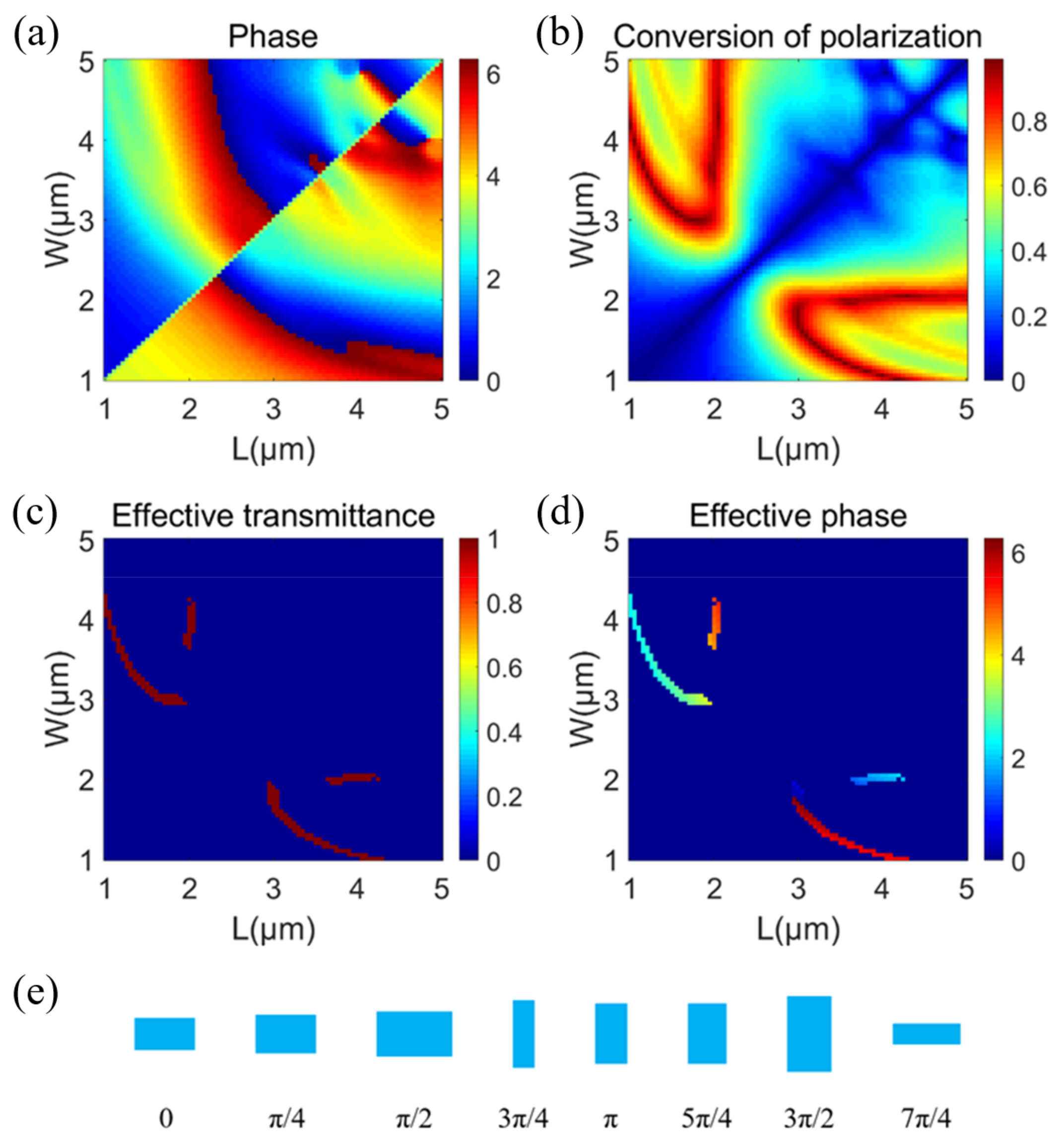
2.1.3. Design of the Orthogonal Circularly Polarized Metalens
2.2. Design of the SAM
3. Results and Discussion
4. Conclusions
Author Contributions
Funding
Institutional Review Board Statement
Informed Consent Statement
Data Availability Statement
Conflicts of Interest
References
- Yu, N.; Capasso, F. Flat optics with designer metasurfaces. Nat. Mater. 2014, 13, 139–150. [Google Scholar] [CrossRef] [PubMed]
- Mueller, J.P.B.; Rubin, N.A.; Devlin, R.C.; Groever, B.; Capasso, F. Metasurface Polarization Optics: Independent Phase Control of Arbitrary Orthogonal States of Polarization. Phys. Rev. Lett. 2017, 118, 113901. [Google Scholar] [CrossRef] [PubMed] [Green Version]
- Byrnes, S.J.; Lenef, A.; Aieta, F.; Capasso, F. Designing large, high-efficiency, high-numerical-aperture, transmissive meta-lenses for visible light. Opt. Express 2016, 24, 5110–5124. [Google Scholar] [CrossRef] [PubMed] [Green Version]
- Shan, D.; Xu, N.; Gao, J.; Song, N.; Liu, H.; Tang, Y.; Feng, X.; Wang, Y.; Zhao, Y.; Chen, X.; et al. Design of the all-silicon long-wavelength infrared achromatic metalens based on deep silicon etching. Opt. Express 2022, 30, 13616–13629. [Google Scholar] [CrossRef]
- Chen, W.T.; Zhu, A.Y.; Sanjeev, V.; Khorasaninejad, M.; Shi, Z.; Lee, E.; Capasso, F. A broadband achromatic metalens for focusing and imaging in the visible. Nat. Nanotech. 2018, 13, 220–226. [Google Scholar] [CrossRef] [Green Version]
- Taghvaee, H.; Liu, F.; Díaz-Rubio, A.; Tretyakov, S. Subwavelength focusing by engineered power-flow conformal metamirrors. Phys. Rev. B 2021, 104, 235409. [Google Scholar] [CrossRef]
- Lin, C.H.; Chen, Y.S.; Lin, J.T.; Wu, H.C.; Kuo, H.T.; Lin, C.F.; Chen, P.; Wu, P.C. Automatic Inverse Design of High-Performance Beam-Steering Metasurfaces via Genetic-type Tree Optimization. Nano. Lett. 2021, 21, 4981–4989. [Google Scholar] [CrossRef] [PubMed]
- Zheng, G.X.; Mühlenbernd, H.; Kenney, M.; Li, G.; Zentgraf, T.; Zhang, S. Metasurface holograms reaching 80% efficiency. Nat. Nanotech. 2015, 10, 308–312. [Google Scholar] [CrossRef] [PubMed]
- Wan, W.W.; Gao, J.; Yang, X.D. Full-Color Plasmonic Metasurface Holograms. ACS Nano 2016, 10, 10671–10680. [Google Scholar] [CrossRef]
- Khorasaninejad, M.; Capasso, F. Metalenses: Versatile multifunctional photonic components. Science 2017, 358, eaam8100. [Google Scholar] [CrossRef] [Green Version]
- Tan, S.; Yang, F.; Boominathan, V.; Veeraraghavan, A.; Naik, G.V. 3D Imaging Using Extreme Dispersion in Optical Metasurfaces. ACS Photonics 2021, 8, 1421–1429. [Google Scholar] [CrossRef]
- Sun, T.; Hu, J.P.; Zhu, X.J.; Xu, F.; Wang, C.H. Broadband Single-Chip Full Stokes Polarization-Spectral Imaging Based on All-Dielectric Spatial Multiplexing Metalens. Las. Phot. Rev. 2022, 16, 2100650. [Google Scholar] [CrossRef]
- Zhu, X.Z.; Cheng, Y.Z.; Chen, F.; Luo, H.; Ling, W. Efficiency adjustable terahertz circular polarization anomalous refraction and planar focusing based on a bi-layered complementary Z-shaped graphene metasurface. J. Opt. Soc. Am. B 2022, 39, 705–712. [Google Scholar] [CrossRef]
- Yang, D.R.; Cheng, Y.Z.; Chen, F.; Luo, H.; Wu, L. Efficiency tunable broadband terahertz graphene metasurface for circular polarization anomalous reflection and plane focusing effect. Dia. Rel. Mater. 2023, 131, 109605. [Google Scholar] [CrossRef]
- Wang, S.M.; Wu, P.C.; Su, V.C.; Lai, Y.C.; Chu, C.H.; Chen, J.W.; Lu, S.H.; Chen, J.; Xu, B.B.; Kuan, C.H.; et al. Broadband achromatic optical metasurface devices. Nat. Commun. 2017, 8, 187. [Google Scholar] [CrossRef] [PubMed]
- Yao, Y.H.; Liu, H.; Wang, Y.F.; Li, Y.R.; Song, B.X.; Wang, R.P.; Povinelli, M.L.; Wu, W. Nanoimprint-defined, large-area meta-surfaces for unidirectional optical transmission with superior extinction in the visible-to-infrared range. Opt. Express 2016, 24, 15362–15372. [Google Scholar] [CrossRef]
- Park, J.S.; Zhang, S.Y.; She, A.; Chen, W.T.; Lin, P.; Yousef, K.M.A.; Cheng, J.X.; Capasso, F. All-glass, large metalens at visible wavelength using deep-ultraviolet projection lithography. Nano Lett. 2019, 19, 8673–8682. [Google Scholar] [CrossRef]
- Balli, F.; Sultan, M.A.; Ozdemir, A.; Hastings, J.T. An ultrabroadband 3D achromatic metalens. Nanophotonics 2021, 10, 1259–1264. [Google Scholar] [CrossRef]
- Li, J.W.; Wang, Y.L.; Liu, S.J.; Xu, T.; Wei, K.; Zhang, Y.D.; Cui, H. Largest aperture metalens of high numerical aperture and polarization independence for long-wavelength infrared imaging. Opt. Express 2022, 30, 28882–28891. [Google Scholar] [CrossRef]
- Zhao, F.; Shen, Z.C.; Wang, D.C.; Xu, B.J.; Chen, X.N.; Yang, Y.M. Synthetic aperture metalens. Photonics Res. 2021, 9, 2388–2397. [Google Scholar] [CrossRef]
- Wang, D.Y.; Han, J.; Liu, H.C.; Tao, S.Q.; Fu, X.Y.; Guo, H.F. Experimental study on imaging and image restoration of optical sparse aperture systems. Opt. Eng. 2007, 46, 103201. [Google Scholar] [CrossRef]
- Sabatke, E.M.; Burge, J.H. Basic principles in the optical design of imaging multiple aperture systems. Proc. SPIE 2002, 4832, 236–248. [Google Scholar]
- Garcia, N.M.; Erausquin, I.D.; Edmiston, C.; Gruev, V. Surface normal reconstruction using circularly polarized light. Opt. Express 2015, 23, 14391–14406. [Google Scholar] [CrossRef] [PubMed]
- Zhang, W.F.; Liang, J.; Ren, L.Y.; Ju, H.J.; Qu, E.S.; Bai, Z.F.; Tang, Y.; Wu, Z.X. Real-time image haze removal using an aperture-division polarimetric camera. Appl. Opt. 2017, 56, 942–947. [Google Scholar] [CrossRef] [PubMed]
- Jin, H.H.; Qian, L.J.; Gao, J.; Fan, Z.G.; Chen, J. Polarimetric calculation method of global pixel for underwater image restoration. IEEE Photonics J. 2021, 13, 1–15. [Google Scholar] [CrossRef]
- Wu, R.Y.; Zhao, Y.Q.; Li, N.; Kong, S.G. Polarization image demosaicking using polarization channel difference prior. Opt. Express 2021, 29, 22066–22079. [Google Scholar] [CrossRef]
- Morel, O.; Meriaudeau, F.; Stolz, C. Polarization imaging applied to 3D reconstruction of specular metallic surfaces. Proc. Spie 2005, 5679, 178–186. [Google Scholar]
- Arbabi, E.; Kamali, S.M.; Arbabi, A.; Faraon, A. Full Stokes imaging polarimetry using dielectric metasurfaces. ACS Photonics 2018, 5, 3132–3140. [Google Scholar] [CrossRef] [Green Version]
- Wang, S.; Wang, X.K.; Kan, Q.; Ye, J.S.; Feng, S.F.; Sun, W.F.; Han, P.; Qu, S.L.; Zhang, Y. Spin-selected focusing and imaging based on metasurface lens. Opt. Express 2015, 23, 26434–26441. [Google Scholar] [CrossRef]
- Chen, S.Q.; Li, Z.; Zhang, Y.B.; Cheng, H.; Tian, J.G. Phase Manipulation of Electromagnetic Waves with Metasurfaces and Its Applications in Nanophotonics. Adv. Optical Mater. 2018, 6, 1800104. [Google Scholar] [CrossRef]
- Li, X.S.; Chen, S.Q.; Wang, D.; Shi, X.T.; Fan, Z.G. Transmissive mid-infrared achromatic bifocal metalens with polarization sensitivity. Opt. Express 2021, 29, 17173–17182. [Google Scholar] [CrossRef] [PubMed]
- Gonzalez, R.C.; Woods, R.E. Digital Image Processing; Addison-Wesley Publishing Company, Inc.: Reading, MA, USA, 1992. [Google Scholar]
- Biggs, D.S.C.; Andrews, M. Acceleration of iterative image restoration algorithms. Appl. Opt. 1997, 36, 8. [Google Scholar] [CrossRef] [PubMed] [Green Version]
- Holmes, T.J.; Bhattacharyya, S.; Cooper, J.A.; Hanzel, D.; Turner, J.N. Light Microscopic Images Reconstructed by Maximum Likelihood Deconvolution. In Handbook of Biological Confocal Microscopy; Pawley, J.B., Ed.; Plenum Press: New York, NY, USA, 1995. [Google Scholar]


| Number | 1 | 2 | 3 | 4 | 5 | 6 | 7 | 8 |
|---|---|---|---|---|---|---|---|---|
| Phase (rad) | 0 | π/4 | π/2 | 3π/4 | π | 5π/4 | 3π/2 | 7π/4 |
| Transmittance | 0.96 | 0.97 | 0.94 | 0.90 | 0.90 | 0.93 | 0.91 | 0.97 |
| Radius (μm) | 0.5 | 1.05 | 1.2 | 1.3 | 1.35 | 1.4 | 1.5 | 1.65 |
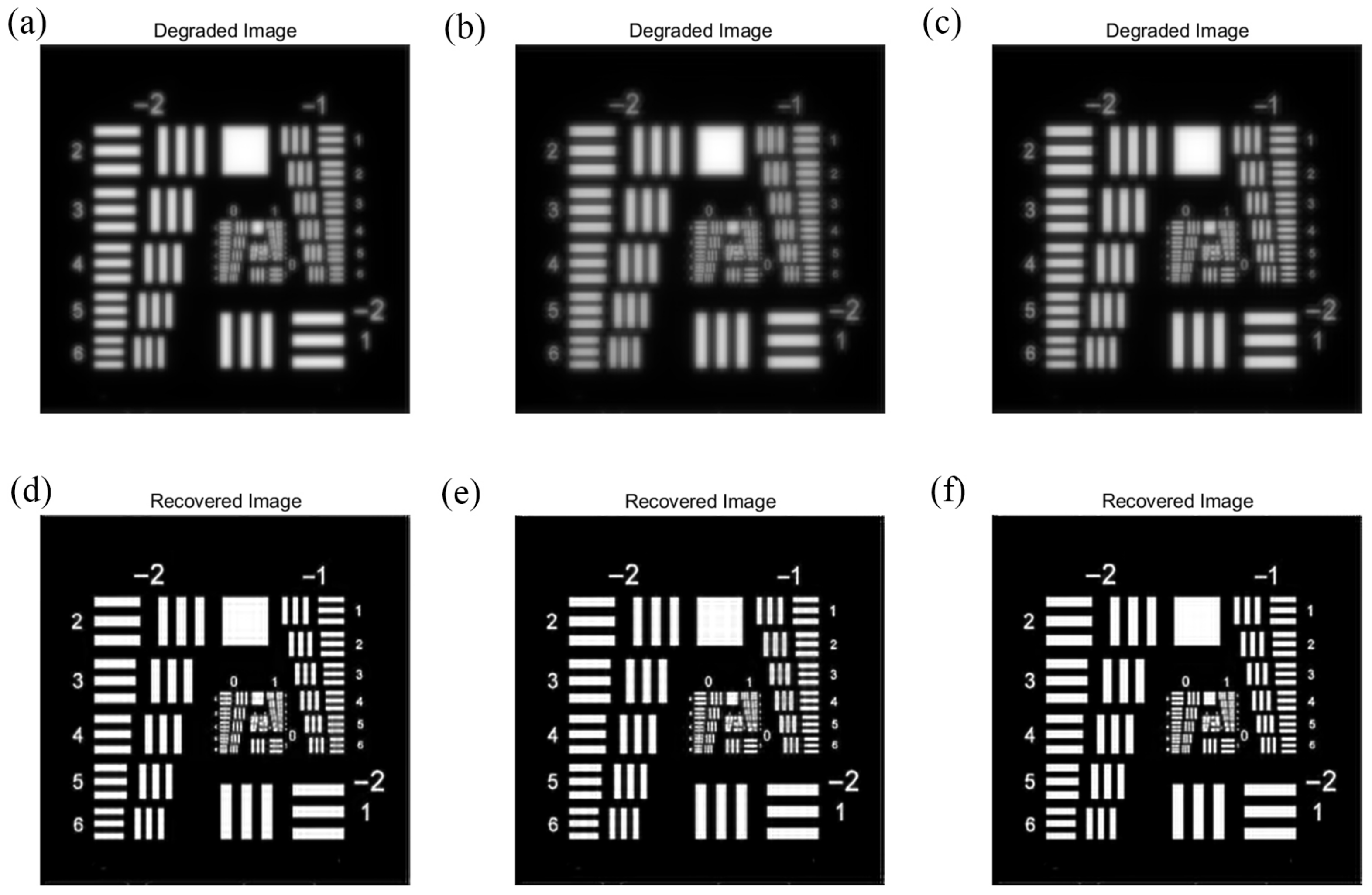
| Array Structures | Degraded Images | Restored Images | ||
|---|---|---|---|---|
| PSNR | SSIM | PSNR | SSIM | |
| Golay3 | 16.5 | 0.49 | 23.6 | 0.92 |
| Cross | 16.2 | 0.44 | 25.7 | 0.94 |
| Annulus | 15.1 | 0.39 | 24.3 | 0.91 |
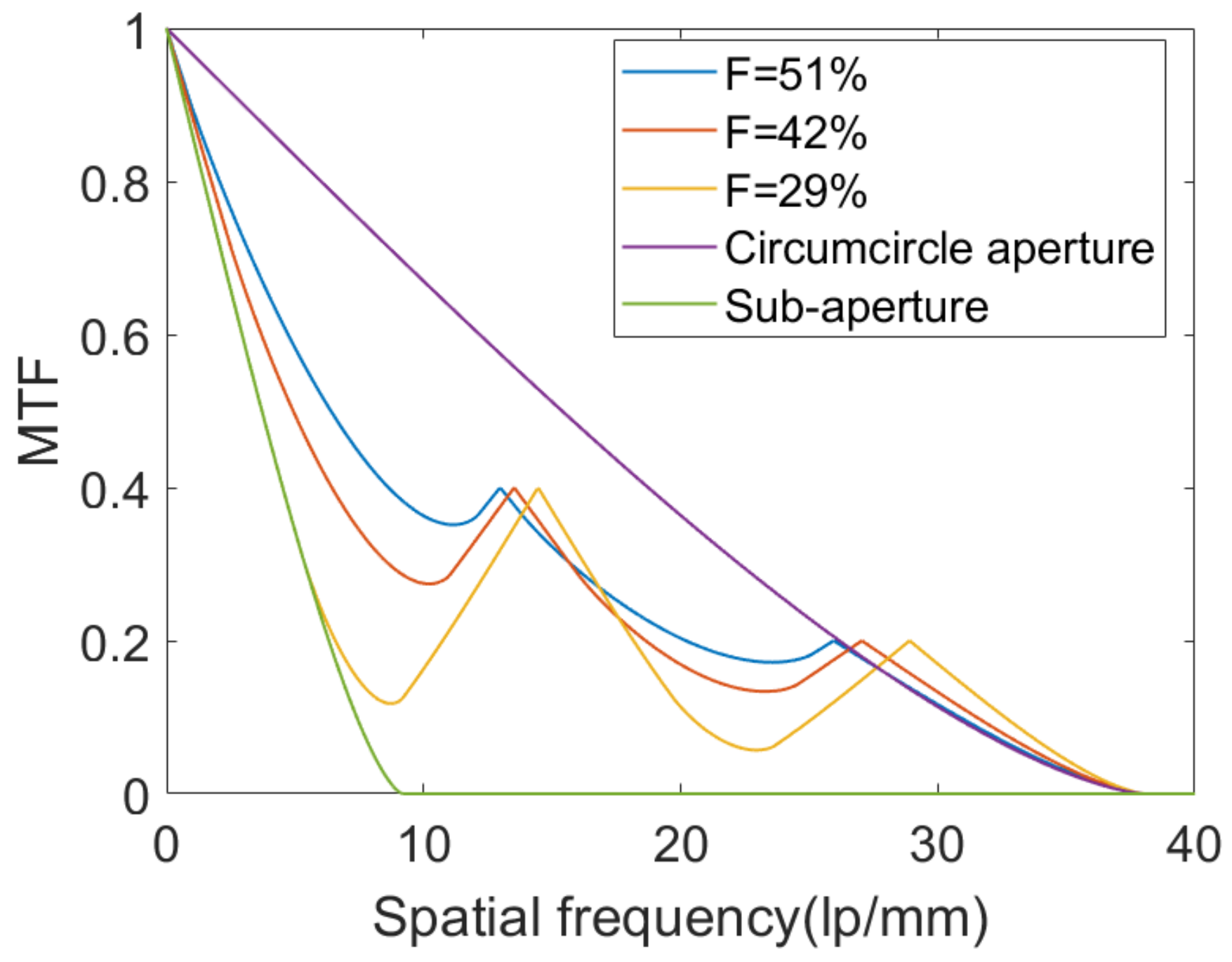
| Array Structures | Filling Factors | PI-SAM | OLP-SAM | OCP-SAM | ||
|---|---|---|---|---|---|---|
| Golay3 | 29% | 24% | 22% | 23% | 22% | 23% |
| 42% | 42% | 39% | 32% | 40% | 41% | |
| 51% | 48% | 44% | 46% | 47% | 47% | |
| Cross | 29% | 24% | 20% | 18% | 22% | 22% |
| 42% | 33% | 31% | 32% | 33% | 33% | |
| 51% | 41% | 38% | 39% | 42% | 42% | |
| Annulus | 29% | 17% | 15% | 15% | 15% | 15% |
| 42% | 27% | 23% | 23% | 23% | 23% | |
| 51% | 30% | 28% | 29% | 29% | 29% | |
Disclaimer/Publisher’s Note: The statements, opinions and data contained in all publications are solely those of the individual author(s) and contributor(s) and not of MDPI and/or the editor(s). MDPI and/or the editor(s) disclaim responsibility for any injury to people or property resulting from any ideas, methods, instructions or products referred to in the content. |
© 2023 by the authors. Licensee MDPI, Basel, Switzerland. This article is an open access article distributed under the terms and conditions of the Creative Commons Attribution (CC BY) license (https://creativecommons.org/licenses/by/4.0/).
Share and Cite
Hu, J.; Dong, Z.; Yang, X.; Xia, L.; Chen, X.; Lu, Y. Polarization-Insensitive, Orthogonal Linearly Polarized and Orthogonal Circularly Polarized Synthetic Aperture Metalenses. Photonics 2023, 10, 348. https://doi.org/10.3390/photonics10040348
Hu J, Dong Z, Yang X, Xia L, Chen X, Lu Y. Polarization-Insensitive, Orthogonal Linearly Polarized and Orthogonal Circularly Polarized Synthetic Aperture Metalenses. Photonics. 2023; 10(4):348. https://doi.org/10.3390/photonics10040348
Chicago/Turabian StyleHu, Jijian, Zhenghong Dong, Xuanwen Yang, Lurui Xia, Xueqi Chen, and Yan Lu. 2023. "Polarization-Insensitive, Orthogonal Linearly Polarized and Orthogonal Circularly Polarized Synthetic Aperture Metalenses" Photonics 10, no. 4: 348. https://doi.org/10.3390/photonics10040348