Communication

Subnanometer-Resolution Nanoparticle Sensing through the Strong Coupling between Surface Plasmon Polariton Whispering Gallery Resonances and Localized Surface Plasmon

School of Physics, Guizhou University, Guiyang 550025, China
*
Author to whom correspondence should be addressed.
Photonics 2023, 10(2), 212; https://doi.org/10.3390/photonics10020212
Submission received: 5 December 2022 / Revised: 7 February 2023 / Accepted: 7 February 2023 / Published: 15 February 2023
(This article belongs to the Special Issue Strong Light Fields Coupled with Plasmonic Nano-Structures)

Abstract

:
High-resolution nanoparticle sensing is very important, and many schemes have been proposed to achieve this goal. Circular nanocavities in which surface plasmon polariton (SPP) whispering gallery mode (WGM) resonances were excited were designed to sense particles of ultra-small size and with high resolution. Localized surface plasmon resonances (LSPRs) were excited when a metal particle was set in the circular cavity. The SPP WGM split into symmetric mode (SM) and antisymmetric mode (ASM) due to the LSPRs scattering into the SPPs. The strong coupling between SM resonance and LSPRs generated positive and opposite modes, which were sensitive to the variation in nanoparticle size and position. Even a small nanometer-sized metal particle introduced LSPRs and produced mode splitting. The WGM mode splitting induced by LSPRs reduced the sensing limit. The simulation results show that 1 nm changes in nanoparticle radius and position led to SM 11.8 nm and 10.2 nm wavelength shifts, respectively. This means that variations of 0.09 nm in size and 0.1 nm in position can be sensed with a 1 nm spectral resolution. The strong coupling between SPP WGM and LSPRs can be applied to sense at a subnanometer resolution.

1. Introduction

Whispering gallery mode (WGM) resonances are usually excited in ring-shaped dielectric waveguides. An optical wave propagates along the ring waveguide by total internal reflection, forming resonances by interfering with itself after a round [1,2,3,4]. The coupling between the electric fields of the degenerate clockwise and counterclockwise modes produces mode splitting [5,6,7]. A high-quality factor in excess of 105 was obtained through localized WGM resonance in the air nanogap of a double-layer crystalline microdisk [8]. WGM resonances with the properties of a high Q value and mode splitting have been studied widely, and many applications have been proposed, such as optical detection [9,10], manipulation [11], laser [12,13], sensing [14,15], storage [16], frequency combing [17], nonlinear optics [18], and acceleration of charged particles [19]. Using a combination of the WGM high-Q and subwavelength confinement of surface plasmon polaritons (SPPs), SPP WGM resonances in metal structures were investigated for ultra-small volumes [20,21,22] and high Q resonances [23,24].
WGM mode splitting, with its self-referencing property, can detect nanoparticles precisely and has received significant attention. WGM mode splitting in dielectric cavities is based on nanoparticles scattering the WGM. The nanoparticle size is derived from particle polarizability through dipole approximation and is proportional to the splitting frequency. Mode splitting in an ultra-high-Q WGM microtoroid resonator was used to detect the size of single nanoparticles as small as 30 nm in radius [10]. In silica WGM resonators, Raman gain-induced loss compensation was used to improve detection, and 10 nm single particles were detected and counted using mode splitting in a WGM Raman microlaser [25]. By monitoring the beat frequency of split-mode Raman lasers in high-Q optical microcavities, a single nanoparticle with a 20 nm radius was detected [26]. Using the monolithic fabrication process, an ultra-high-Q WGM resonator was able to detect and measure single nanoparticles with a theoretical detection limit of one nanometer [27]. Through mode splitting, the sizing of a single nanoparticle was realized in a range of tens of nanometers.
Many schemes have been proposed to sense nanoparticles based on plasmon resonance interactions. In metallic cavities, destructive interferences between different SPP resonant modes lead to the destructive superposition of spectra, producing plasmon Fano resonance (PFR) [28,29,30] and plasmon-induced transparency (PIT) [31,32,33]. Nanoscale sensing is realized through PFR and PIT. The localized surface plasmon resonance (LSPR) in a metal structure interferes with SPP F–P resonance and generates Fano resonance, which can be used to sense distance variations of a few nanometers [34,35]. This sensitivity is related to the enhanced near field, with the WGMs of dielectric resonators exhibiting ultrahigh electric and magnetic field enhancements. With the construction a small gap in a disk dimer, the electric field enhancement in the gap can reach an ultrahigh value of ∼ 10 3 times [36]. Coupling between surface lattice resonances (SLRs) and Fabry–Pérot (F–P) resonances is achieved by placing the metal nanorod array in a microcavity. Results show that the electric field intensity of the bonding split mode can be enhanced by up to 1935 times, which is about three times the enhancement of SLR [37].
LSPR is ultra-sensitive to the surrounding background. An LSPR with an ultra-small volume and high intensity can scatter SPPs along a metal surface, which can lead to WGM splitting. WGM splitting induced by LSPRs can improve the sensing limitation. Embedding metal particles in a cavity may lead to SPP WGM coupling to LSPRs. Such coupling is highly anticipated for ultra-high-resolution optical sensing. In this study, we designed a circular cavity beside a waveguide in which travelling SPP WGM resonances are excited. A metal particle was then embedded in the cavities. SPP WGM splitting and strong coupling with LSPRs were observed, which can be used sense nanoparticles. Furthermore, strong resonance coupling and sensing properties were investigated.

2. Methods and Theory

A circular cavity was designed on a metal plate, as shown in Figure 1a. A waveguide beside the cavity was used to excite resonances. The width of the waveguide was w = 50   nm , g represents the gap between the waveguide and the cavity, and r is the radius of the circular cavity. The purple regions were composed of metal (Ag), and the remaining region was a vacuum with n = 1 . The dispersive property of Ag is depicted through a Drude model:
ε m = ε ω p 2 ω 2 + i ω γ ,
where the permittivity constant is ε = 3.7, the plasma resonant frequency is ω p = 9.1 eV, the loss constant is γ = 0.018   eV , and ω is the frequency of the incident wave. A plane wave with an electric field (Ey) was incident from the input waveguide and interacted with structures. The two-dimensional finite difference time domain method (2D FDTD) was used; we compiled two-dimensional FDTD codes to simulate the interaction between structures and electromagnetic waves. In the 2D FDTD simulation, the mesh grid-cell size was set to x = y = 0.5   nm . Perfect matching layers were used to truncate computational regions. The propagated SPPs interacted with the cavity structures, as illustrated in Figure 1a. Transmittance was defined as the ratio of energy through the output to the input.
T = P o u t P i n .
The transmissions through the structure were calculated through 2D FDTD and Fourier transform. First, a time pulse was generated to excite SPP propagation along the waveguide. The output pulse was obtained at the output port. The spectrum was then obtained through Fourier transformation of the time output pulse. The incident spectrum was obtained using only the waveguide in the structure. A varied spectrum could also be obtained by varying the design of the cavity or particle beside the waveguide. The transmission spectrum was finally obtained after normalizing the varied spectrum to the incident spectrum. Thus, the travelling loss in the waveguide was excluded. This facilitated the investigation of resonance in the cavity. To reduce the influence of other independent variables, the distance between the input and output remained constant at all times.
The transmission was calculated when r = 250   nm and g = 20   nm , as shown in Figure 1b. There were four dips in the spectrum at wavelengths of 449.1 nm, 460.2 nm, 606.2 nm, and 969.2 nm, labeled as dips 1–4, respectively. The four dips red-shifted with increasing radius ( r ), as shown in Figure 1c. To demonstrate that the dips in the transmission spectrum correspond to resonance, the reflection spectrum was calculated, as shown in Figure 1b. The dips in the transmission spectrum clearly correspond to the peaks in the reflection spectrum. The SPPs propagating in the waveguide are coupled into the cavity and excite resonances in the cavity, resulting in dips in the resonance wavelength. At the same time, the resonances in the cavity also produce backward SPPs in the waveguide, forming the peaks in the reflection spectrum. Therefore, the wavelengths of the dips in the transmission spectrum correspond to those of the peaks in the reflection spectrum, both of which were caused by the resonances in the cavity.
To reveal the underlying mechanism, the magnetic field distribution corresponding to the four dips is presented in Figure 2. For dip 1 at 449.1 nm, the resonance mode from the magnetic field module ( H ) in Figure 2a or the phase (P(H)) in e cannot be seen. For dip 2 at 460.1 nm, the H distribution in Figure 2b and the phase (P(H)) in Figure 2f indicate that SPP WGM with an order m = 3 was excited along the inwall of the cavity. For dip 3 at 606.2 nm and dip 4 at 969.2 nm, it can be seen that both dips correspond to SPP WGM modes with order of m = 2 and 1, respectively.
Dips 2, 3, and 4 are attributed to SPP WGM resonances. Here, SPPs travelling along the circular inwall cause interference after a round trip, thereby forming resonances. In a circular cavity, the SPPs propagate on the inwall of the cavity. The electrical field intensity reaches the maximum on the metal surface and then decays exponentially within the cavity. The electromagnetic field extends into the cavity within the penetration depth of the wavelength. For small cavities with a radius equivalent to or smaller than the resonance wavelength, electromagnetic field penetration into the cavity cannot be ignored. The effective optical geometry path of SPP WGMs is smaller than the circumference ( 2 π r ) with a round trip. Considering the penetration, an effective radius ( r e f f ) is introduced. WGM resonances occur when:
2 π r e f f = m λ m ,               m = 1 , 2 , 3
Here, m is the resonance order. Depending on the resonance condition, the effective radius is r e f f = 154.3 , 193.1 , and 219.8   nm for first-, second-, and third-order WGMs in a 250 mm circular cavity, respectively.
For dip 1 at 449.1 nm, the electric field module distribution shown in Figure 2i indicates that resonance exists in the cavity. The E x phase shown in Figure 2j and the E y phased shown in Figure 2k suggest standing-wave resonances in the cavity. Second-order standing resonance appears in both the x and y directions, resulting in dip 1 at 449.1 nm in the cavity.
The quality factor (Q) values, defined as the ratio of dip wavelength to full width at half minimum, were calculated for the four dips, as shown in Figure 1d. The Q of the four dips first increases and then decreases with its red shift. The maximal Q values of the four dips are 1088, 499, 522, and 1163, respectively.

3. Results and Discussion

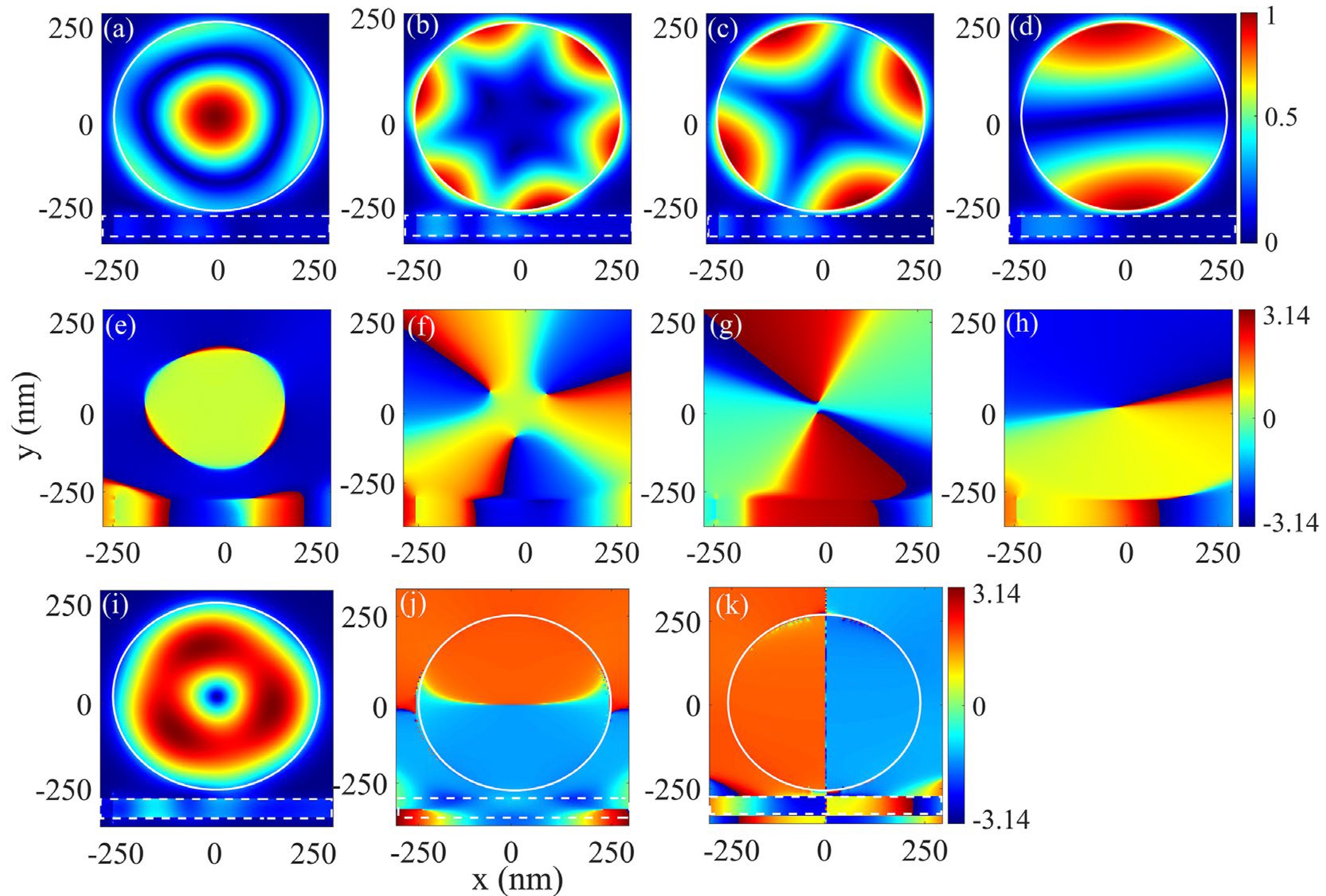
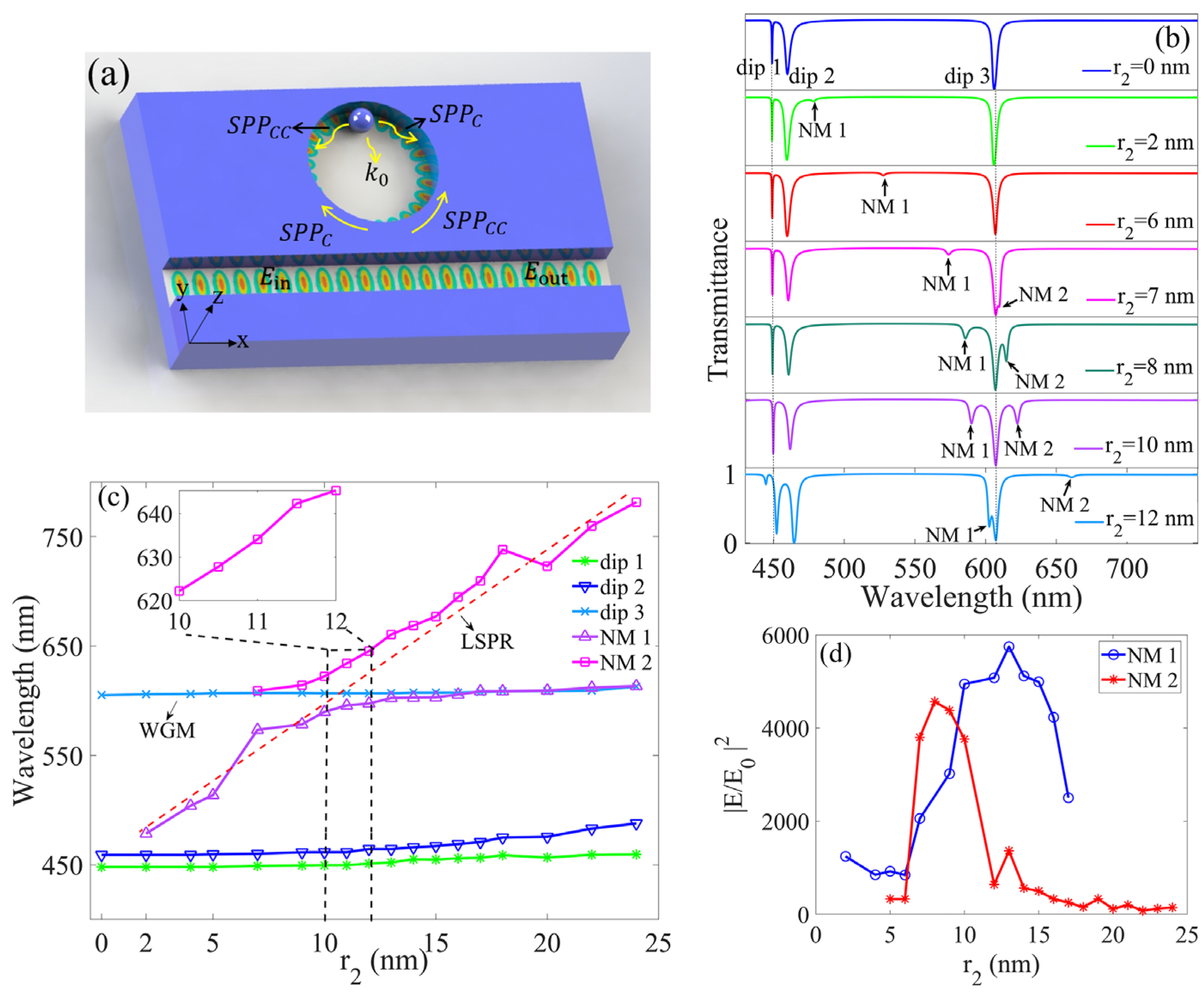
3.1. Strong Coupling between SPP WGM and LSPR

The resonances in the structure were considered for a metal particle with a radius of r 2 set in a cavity, as shown in the schematics in Figure 3a. The particle touches the inwall of the cavity. The transmissions of different particles are shown in Figure 3b. Two new dips labeled as NM 1 and 2 appear as r 2 = 2.0   nm and r 2 = 7.0   nm, respectively. More detailed variations in the dips are shown in Figure 3c. Both dips red shift with increasing r 2 . The wavelengths of dips 1–3 clearly remained almost unchanged after the metal particle was embedded. The light-blue line indicates that dip 3 was caused by the second-order SPP WGM. New dips NM 1 and 2 are considered to be caused by LSPRs, which were excited when the metal particle was set in the cavity. When the particle size increased, the LSPRs divided into lower and upper branches. For the lower branch, the LSPR red-shifted almost linearly when the particle radius increased from 2 nm to 10 nm. For the upper branch, the LSPR also red-shifted in the same way as the particle radius increased from 10 nm to 24 nm. The red dotted line indicates the entire shift in the LSP mode with the increase in particle size. The SPP WGM and LSPR spectra exhibit clear anticrossing behavior, which indicates the strong coupling between WGM and LSPR. Rabi splitting was extracted as the minimal splitting between two LSPR branches when r 2 = 10.0 nm, and dips NM 1 and 2 were located at 589.8 and 622.2 nm, respectively. The corresponding vacuum Rabi splitting of Ω = 112   meV was obtained with zero detuning. The Rabi splitting ( Ω ) was larger than the WGM resonance spectral width ( γ dip 3 ) of 14 meV, satisfying the criteria for strong coupling. The strong coupling between LSPR and WGM resonance caused dips NM 1 and 2 to deepen.
The interaction mechanism between SPP WGM and LSPR was analyzed. The SPP WGM resonances included both clockwise and counterclockwise modes, and their frequencies were degenerate. When a metal particle was set in the cavity, LSPR was excited in the gap between the particle and the inwall. At the same time, LSPR excited SPPs propagation along the inwall surface in both the clockwise and counterclockwise directions, as illustrated in Figure 3a. Coupling was produced between the degenerate clockwise SPP c and counterclockwise mode ( SPP cc ) by the LSPR exciting the SPPs in both the clockwise and counterclockwise directions. The superposition generated standing-wave modes, i.e., a symmetric mode ( SPP + ) and an antisymmetric mode ( SPP ):
SPP + = aSPP c + bSPP cc
SPP = aSPP c bSPP cc
where a and b are complex coefficients. For the antisymmetric mode ( SPP ) with a particle at a node, the particle introduced less loss and barely affected the SPP . For the symmetric mode ( SPP + ) with a particle at an antinode, the particle introduced a relatively large loss and raised the effective refractive index experienced by the symmetric mode. The wavelength and intensity of the symmetric mode ( SPP + ) therefore varied with r 2 . The SPP WGM split into SPP and SPP + due to the LSPR exciting the SPPs. Based on the superposition principle, it is believed that dips NM 1 and 2 were deepened by the strong coupling between the symmetric mode ( SPP + ) and LSPR when r 2 was near 10.0   nm . On the other hand, the antisymmetric mode ( SPP ) could not couple with the LSPR because the particle was located at a node. The antisymmetric mode ( SPP ) led to dip 3 after the metal particle was set.
To verify the interaction mechanism, the near-field distributions are presented in Figure 4. The white solid and dashed lines represent the contours of the circular cavity and particle, respectively. When r 2 = 10.0 nm, dip NM 1 was located at 589.8 nm. The distributions of the near-field module ( E ) around the particle and all the phases of E y are shown in Figure 4a,b, respectively. The near-field distribution shown in Figure 4a indicates that high-intensity LSPR was excited in the gap between the particle and the cavity inwall. The maximum of the electric field module was 70.4 times the incident SPP intensity in the waveguide. The phase distribution of E y in the whole cavity is shown in Figure 4b. The phase in the cavity is clearly divided into two areas with a difference in the π phase between them. The particle was located on an antinode. This indicates that a standing wave formed in the cavity. The LSPR phase is the same as that of the standing wave where the particle was located, known as positive coupling between the symmetric mode ( SPP + ) and LSPR. This is similar to dip NM 2 at 622.2 nm with r 2 = 10.0 nm. The distributions of the near-field module ( E ) around the particle and the E y phase in the cavity are shown in Figure 4c,d, respectively. LSPRs with enhanced intensity appear in the gap between the particle and the inwall. The maximum of the electric field module is 61.5 times the incident SPP intensity in the waveguide. As seen in Figure 4d, a standing wave was produced in the whole cavity, and the particle was located on an antinode. The LSPR phase is opposite to that of the standing wave where the particle was located, known as opposite coupling between the symmetric mode ( SPP + ) and LSPR.
The strong coupling between LSPR and SPP WGM exerts an influence on the near-field intensity. Near-field enhancement of the coupling was calculated, as shown in Figure 3d. For dips NM 1 and 2, the intensity maxima first increased and then decreased with r 2 . At the strong coupling region with r 2 near 10 nm, the near-field intensity was enhanced. When r 2 = 13.0 nm, the intensity maximum of NM 1 was 5.7 × 10 3 times the incident SPP intensity in the waveguide. The near-field intensity maximum of NM 2 was 4.6 × 10 3 times the SPP incident intensity in the waveguide when r 2 = 8.0 nm. The strong coupling between SPP WGM and LSPR enhanced the near field in the gap.
According to the superposition principle, dips 2 and 3 became antisymmetric modes ( SPP ) after the particle was introduced. Their near fields and E y phases became standing-wave distributions. Only the electric fields of dip 3 are shown in Figure 4e for module E and in Figure 4f for the E y phases in the cavity. It can be seen that the near field became weak, with the module maximum of 21.3 times the incident SPP intensity in the waveguide. The particle was located at a node, as shown in Figure 4f. Clearly, an antisymmetric mode ( SPP ) cannot couple with the LSPR in the gap between the particle and the cavity inwall.
A particle deviated from the inwall of the cavity, as illustrated in Figure 5a. Transmission spectra for different spaces ( h ) are shown in Figure 5b. The particle radius ( r = 12.0 nm) remained unchanged, and dips 1, 2, and 3 were maintained. A new dip emerged near dip 2 when h < 2.0 nm. The variations in resonance modes with space ( h ) are shown in Figure 5c. Dip 2 began to split when h < 2.0 nm. When h 2.5 nm, the particle did not work, and LSPR could not be excited. When h < 2.0 nm, the particle worked. The LSPR between the particle and cavity inwall was excited and interacted with WGM, leading to second-order SPP WGM mode splitting. Figure 5d shows the near-field module of dip NM 3 at 466.3 nm when h = 1.0 nm. LSPR was clearly excited at the gap center. The phase distribution of E y shown in Figure 5e illustrates that a standing wave formed in the cavity and that the particle was located at an antinode. These results indicate that the LSPR at the gap center led to second-order WGM splitting into SM and ASM. Strong coupling between the second-order WGM SM and LSPR then occurred. Dip NM 3 originated from the positive strong coupling between the second-order WGM SM and LSPR. It is possible that the opposite strong coupling mode occurred outside of the considered wavelength range and therefore cannot be seen. Mode splitting was useful to sense distances below 1 nm with subnanometer resolution.

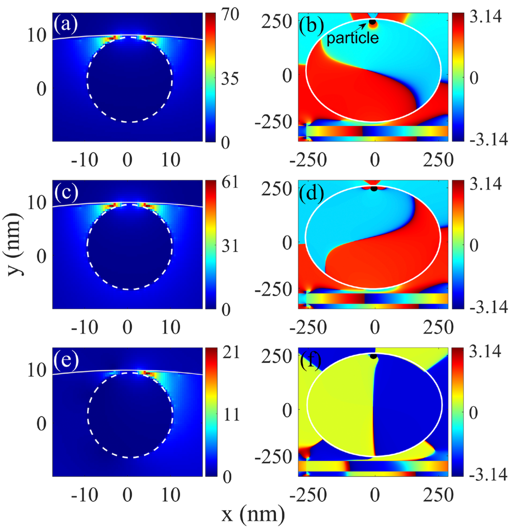
3.2. Sensing Properties of the Coupling between LSPR and SPP WGM

LSPR was sensitive to the size and position of the particle in the cavity. The mode splitting of WGM induced by LSPR was able to sense the variation in nanoparticle size and position, was immune to noise, and had a self-referencing property. We analyzed the size and position-sensing resolutions. The size-sensing resolution (SSR) was defined as the ratio of changed wavelength ( Δ λ ) of SPP + relative to the variation in particle radius ( Δ r ).
SSR = Δ λ Δ r
When the particle size increased from 10 nm to 12 nm in 0.5 nm steps, dip NM 2 red-shifted almost linearly, as shown in the insert in Figure 3c. The SSRs of dip NM 2 were calculated according to Equation (6). The average SSR was 11.8 when r increased from 10 to 12 nm. This means that the variation of 0.09 nm in radius could be sensed with a 1 nm spectral resolution. Subnanometer resolution in nanoparticle size sensing could be realized through the mode splitting induced by LSPR.
The mode splitting was sensitive to the space between the particle and the inwall. In the same way, the position-sensing resolution was defined as the ratio of the splitting wavelength ( Δ λ ) of SPP + relative to the variation in particle position ( Δ h ).
PSR = Δ λ Δ h
PSR was calculated according to Equation (7). When h changed from 0.5 to 1 nm, PSR = 10.2 . This means that the 0.1 nm variation in position could be sensed with 1 nm spectral resolution. As the distance between the particle and the cavity inwall increased, the PSR decreased. The average PSR was 6.7 when h increased from 0.5 to 2.5. When the particle was far from the cavity inwall, the PSR decreased. This may be attributed to the LSPR property, which varied exponentially with the gap.

4. Conclusions

In summary, nanocircular cavities were designed on metal (Ag) plates. SPP WGM resonances were generated in the cavity. A metal particle was set in the cavity to excite LSPRs. The SPP WGM split into SM and ASM when LSPRs scattered into SPPs. WGM mode splitting induced by LSPRs improved sensing limitations. The strong coupling between symmetric WGM resonance and LSPRs generated positive and opposite strong coupling modes, enhancing the near field by up to 5.7 × 10 3 times the incident SPP intensity in the waveguide. Simulations showed that the subnanometer position and size variations in the metal particle led to extreme SM wavelength shifts. The size and position-sensing resolutions reached 11.8 and 10.2, respectively. Compared to a resolution of tens of nanometer resolution through WGM splitting, subnanometer sensing resolutions for the position and size of a metal particle can be realized with a 1 nm spectral resolution. The strong coupling between SPP WGM and LSPR has wide applications, such as near-field enhancement, nonlinear optics, and sensing with subnanometer resolution.

Author Contributions

Conceptualization, H.Y. and Y.-G.C.; methodology, H.Y. and Y.-G.C.; software, H.Y.; validation, H.Y.; formal analysis, H.Y. and Y.-G.C.; investigation, H.Y. and Y.-G.C.; data curation, H.Y.; writing—original draft preparation, H.Y. and Y.-G.C.; writing—review and editing, H.Y. and Y.-G.C.; visualization, H.Y.; supervision, Y.-G.C.; project administration, Y.-G.C.; funding acquisition, Y.-G.C. All authors have read and agreed to the published version of the manuscript.

Funding

This work was supported by the National Natural Science Foundation of China (grant no. 11764006).

Institutional Review Board Statement

Not applicable.

Informed Consent Statement

Not applicable.

Data Availability Statement

The data are available upon request from the authors.

Conflicts of Interest

The authors declare no conflict of interest.

References

  1. Oraevsky, N. Whispering-gallery waves. Quantum Electron. 2002, 32, 377–400. [Google Scholar] [CrossRef]
  2. Vahala, K.J. Optical microcavities. Nature 2003, 424, 839–846. [Google Scholar] [CrossRef] [PubMed]
  3. Schweiger, G.; Weigel, T.; Ostendorf, A. Geometrical-optics analysis of whispering-gallery modes in the layer of a coated spherical resonator. Phys. Rev. A 2020, 102, 053506. [Google Scholar] [CrossRef]
  4. Fang, Z.; Haque, S.; Farajollahi, S.; Luo, H.; Lin, J.; Wu, R.; Zhang, J.; Wang, Z.; Wang, M.; Cheng, Y.; et al. Polygon coherent modes in a weakly perturbed whispering gallery microresonator for efficient second harmonic, optomechanical, and frequency comb generations. Phys. Rev. Lett. 2020, 125, 173901. [Google Scholar] [CrossRef]
  5. Xie, R.R.; Qin, G.Q.; Zhang, H.; Wang, M.; Li, G.Q.; Ruan, D.; Long, G.L. Phase-controlled dual-wavelength resonance in a self-coupling whispering-gallery-mode microcavity. Opt. Express 2021, 46, 773–776. [Google Scholar] [CrossRef]
  6. Yi, X.; Xiao, Y.F.; Liu, Y.C.; Li, B.B.; Chen, Y.L.; Li, Y.; Gong, Q. Multiple-rayleigh-scatterer-induced mode splitting in a high-Q whispering-gallery-mode microresonator. Phys. Rev. A 2011, 83, 23803. [Google Scholar] [CrossRef]
  7. Ghalanos, G.N.; Silver, J.M.; Bino, L.D.; Moroney, N.; Zhang, S.; Woodley, M.T.M.; Svela, A.; Del’Haye, P. Kerr-nonlinearity-induced mode-splitting in optical microresonators. Phys. Rev. Lett. 2020, 124, 223901. [Google Scholar] [CrossRef]
  8. Zheng, Y.; Fang, Z.; Liu, S.; Cheng, Y.; Chen, X. High-Q exterior whispering-gallery dodes in a double-layer crystalline microdisk resonator. Phys. Rev. Lett. 2019, 122, 253902. [Google Scholar] [CrossRef] [Green Version]
  9. Zhi, Y.; Yu, X.C.; Gong, Q.; Yang, L.; Xiao, Y.F. Single nanoparticle detection using optical microcavities. Adv. Mater. 2017, 29, 1604920. [Google Scholar] [CrossRef]
  10. Zhu, J.; Ozdemir, S.K.; Xiao, Y.F.; Li, L.; He, L.; Chen, D.R.; Yang, L. On-chip single nanoparticle detection and sizing by mode splitting in an ultrahigh-Q microresonator. Nat. Photonics 2010, 4, 46. [Google Scholar] [CrossRef]
  11. Cai, H.; Poon, A.W. Optical manipulation of microparticles using whispering-gallery modes in a silicon nitride microdisk resonator. Opt. Lett. 2011, 36, 4257–4259. [Google Scholar] [CrossRef] [Green Version]
  12. Kippenberg, T.J.; Spillane, S.M.; Vahala, K.J. Modal coupling in traveling-wave resonators. Opt. Lett. 2002, 27, 1669–1671. [Google Scholar] [CrossRef] [Green Version]
  13. Ge, K.; Ruan, J.; Cui, L.B.; Guo, D.; Tong, J.H.; Zhai, T.R. Dynamic manipulation of WGM lasing by tailoring the coupling strength. Opt. Express 2022, 30, 28752–28761. [Google Scholar] [CrossRef] [PubMed]
  14. Guendelman, G.; Lovsky, Y.; Yacoby, E.; Mor, O.E.; Kaplan-Ashiri, I.; Goldbart, O.; Dayan, B. Three-dimensional sensing of arbitrarily shaped nanoparticles by whispering gallery mode resonators. Opt. Express 2020, 28, 31297–31315. [Google Scholar] [CrossRef]
  15. Shangguan, Q.; Chen, Z.; Yang, H.; Cheng, S.; Yang, W.; Yi, Z.; Wu, X.; Wang, S.; Yi, Y.; Wu, P. Design of Ultra-Narrow Band Graphene Refractive Index Sensor. Sensors 2022, 22, 6483. [Google Scholar] [CrossRef]
  16. Saglamyurek, E.; Hrushevskyi, T.; Rastogi, A.; Heshami, K.; Leblanc, L.J. Coherent storage and manipulation of broadband photons via dynamically controlled Autler-Townes splitting. Nat. Photonics 2018, 12, 774. [Google Scholar] [CrossRef] [Green Version]
  17. Daugey, T.; Billet, C.; Dudley, J.; Merolla, J.M.; Chembo, Y.K. Kerr optical frequency comb generation using whispering-gallery-mode resonators in the pulsed-pump regime. Phys. Rev. A 2021, 103, 023521. [Google Scholar] [CrossRef]
  18. Kippenberg, T.J.; Spillane, S.M.; Vahala, K.J. Kerr-nonlinearity optical parametric oscillation in an ultrahigh-Q toroid microcavity. Phys. Rev. Lett. 2004, 93, 083904. [Google Scholar] [CrossRef] [PubMed] [Green Version]
  19. Zakowicz, W. Whispering-Gallery-Mode Resonances: A New Way to Accelerate Charged Particles. Phys. Rev. Lett. 2005, 95, 114801. [Google Scholar] [CrossRef] [Green Version]
  20. Kuttge, M.; García de Abajo, F.J.; Polman, A. Ultrasmall mode volume plasmonic nanodisk resonators. Nano Lett. 2010, 10, 1537–1541. [Google Scholar] [CrossRef]
  21. Kwon, S.H. Deep subwavelength plasmonic whispering gallery-mode cavity. Opt. Express 2012, 20, 24918–24924. [Google Scholar] [CrossRef]
  22. Lou, F.; Yan, M.; Thylen, L.; Qiu, M.; Wosinski, L. Whispering gallery mode nanodisk resonator based on layered metal-dielectric waveguide. Opt. Express 2014, 22, 8490–8502. [Google Scholar] [CrossRef]
  23. Zhao, J.; Liu, X.; Qiu, W.; Ma, Y.; Huang, Y.; Wang, J.X.; Qiang, K.; Pan, J.Q. Surface-plasmon-polariton whispering-gallery mode analysis of the graphene monolayer coated InGaAs nanowire cavity. Opt. Express 2014, 22, 5754–5761. [Google Scholar] [CrossRef]
  24. Min, B.; Ostby, E.; Sorger, V.; Ulin-Avila, E.; Lan, Y.; Zhang, X.; Vahala, K. High-Q surface-plasmon-polariton whispering-gallery microcavity. Nature 2009, 457, 455–458. [Google Scholar] [CrossRef]
  25. Li, B.B.; Clements, W.R.; Yu, X.C.; Shi, K.; Gong, Q.; Xiao, Y.F. Single nanoparticle detection using split-mode microcavity Raman lasers. Proc. Natl. Acad. Sci. USA 2014, 111, 14657–14662. [Google Scholar] [CrossRef] [Green Version]
  26. Özdemir, Ş.K.; Zhu, J.; Yang, X.; Peng, B.; Yilmaz, H.; He, L.; Faraz, M.; Huang, S.H.; Long, L.L.; Yang, L. Highly sensitive detection of nanoparticles with a self-referenced and self-heterodyned whispering-gallery Raman microlaser. Proc. Natl. Acad. Sci. USA 2014, 111, 3836–3844. [Google Scholar] [CrossRef] [PubMed] [Green Version]
  27. Özdemir, Ş.K.; He, L.; Zhu, J.; Monifi, F.; Kim, W.; Kenechukwu, O.; Yilmaz, H.; Huang, S.H.; Yang, L. On-chip whispering-gallery-mode microlasers and their applications for nanoparticle sensing. Integr. Opt. Devices Mater. Technol. XVII SPIE 2013, 8627, 132–141. [Google Scholar]
  28. Miroshnichenko, A.E.; Flach, S.; Kivshar, Y. Fano resonances in nanoscale structures. Rev. Mod. Phys. 2010, 82, 2257. [Google Scholar] [CrossRef] [Green Version]
  29. Fang, Y.H.; Wen, K.H.; Li, Z.F.; Wu, B.Y.; Chen, L.; Zhou, J.Y.; Zhou, D.Y. Multiple Fano resonances based on end-coupled semi-ring rectangular resonator. IEEE Photonics J. 2019, 11, 4801308. [Google Scholar] [CrossRef]
  30. Khan, A.D.; Miano, G. Plasmonic Fano resonances in single-layer gold conical nanoshells. Plasmonics 2013, 8, 1429–1437. [Google Scholar] [CrossRef]
  31. Liu, H.X.; Chen, Y.G. Localized surface plasmon induced transparency and spatial resolution enhancement of nanosensors. Phys. Scr. 2021, 96, 125622. [Google Scholar] [CrossRef]
  32. Zhu, Z.H.; Wang, B.Y.; Yan, X.; Liu, Y.; Zeng, Q.D.; Wang, T.; Yu, H.Q. Dynamically tunable multiband plasmon-induced transparency effect based on graphene nanoribbon waveguide coupled with rectangle cavities system. Chin. Phys. B 2022, 31, 84210. [Google Scholar] [CrossRef]
  33. Chen, H.; Zhang, Z.; Zhang, X.; Han, Y.; Zhou, Z.; Yang, J. Multifunctional plasmon-induced transparency devices based on hybrid metamaterial-waveguide systems. Nanomaterials 2022, 12, 3273. [Google Scholar] [CrossRef]
  34. Zhou, T.; Gou, X.Y.; Xu, W.; Li, Y.; Zhai, X.; Li, H.J.; Wang, L.L. Dynamically tunable plasmon-induced transparency in a T-shaped cavity waveguide based on bulk Dirac semimetals. Plasmonics 2021, 16, 323–332. [Google Scholar] [CrossRef]
  35. Wu, X.; Zheng, Y.; Luo, Y.; Zhang, J.; Yi, Z.; Wu, X.; Cheng, S.; Yang, W.; Yu, Y.; Wu, P. A four-band and polarization-independent BDS-based tunable absorber with high refractive index sensitivity. Phys. Chem. Chem. Phys. 2021, 23, 26864–26873. [Google Scholar] [CrossRef] [PubMed]
  36. Du, X.J.; Yang, Z.J.; Hu, M.L.; Ma, L.; He, J. Ultrahigh electric and magnetic near field enhancement based on high-Q whispering gallery modes in subwavelength all-dielectric resonators. Appl. Phys. Express 2021, 14, 082004. [Google Scholar] [CrossRef]
  37. Shi, Y.; Dong, Y.; Sun, D.; Li, G. Significant Near-Field Enhancement over Large Volumes around Metal Nanorods via Strong Coupling of Surface Lattice Resonances and Fabry–Pérot Resonance. Materials 2022, 15, 1523. [Google Scholar] [CrossRef]
Figure 1. Transmission properties of the cavity–waveguide system. (a) Structural schematic. (b) The transmission and reflection spectra. (c) Influence of radius ( r ) on transmission. (d) Q variations in four dips.
Photonics 10 00212 g001
Figure 2. The magnetic and electric field distributions for four dips. For dip 1 at 449.1 nm, the distributions of (a) the magnetic field module ( H ) and (e) phases (P(H)). For dip 2 at 460.1 nm, the distributions of (b) H and (f) phases (P(H)). For dip 3 at 606.2 nm, the distributions of (c) H and (g) phases (P(H)). For dip 4 at 969.2 nm, the distributions of (d) H and (h) phases (P(H)). For dip 1 at 449.1 nm, the distributions of (i) the electric field module ( E ) and (j) E x , and (k) E y phases.
Photonics 10 00212 g002
Figure 3. Resonances of an embedded metal particle. (a) Structural schematic. (b) Spectra of different particles. (c) The variation in resonance modes with particle radius ( r 2 ). (d) Near-field enhancement due to the coupling between LSPR and SPP WGM.
Photonics 10 00212 g003
Figure 4. The near-field module around the particle and the E y phase distributions in whole cavity at resonances with r 2 = 10.0 nm. Dip NM 1 centered at 589.8 nm, as well as (a) E and (b) E y phases. Dip NM 2 centered at 622.2 nm, as well as (c) E and (d) E y phases. Dip 3 centered at 606.8   nm, as well as (e) E and (f) E y phases.
Photonics 10 00212 g004
Figure 5. Resonances with a particle deviating from the inwall of cavity. (a) Structure. (b) Spectra for different spaces. (c) Mode variations with space ( h ). For dip NM 3 centered at 466.3 nm, (d) near-field module and (e) the phase distribution of E y .
Photonics 10 00212 g005
Disclaimer/Publisher’s Note: The statements, opinions and data contained in all publications are solely those of the individual author(s) and contributor(s) and not of MDPI and/or the editor(s). MDPI and/or the editor(s) disclaim responsibility for any injury to people or property resulting from any ideas, methods, instructions or products referred to in the content.

