Key Space Enhancement in Chaotic Secure Communication Utilizing Monolithically Integrated Multi-Section Semiconductor Lasers

 , , ,
, , ,
Abstract
:1. Introduction
2. Methods
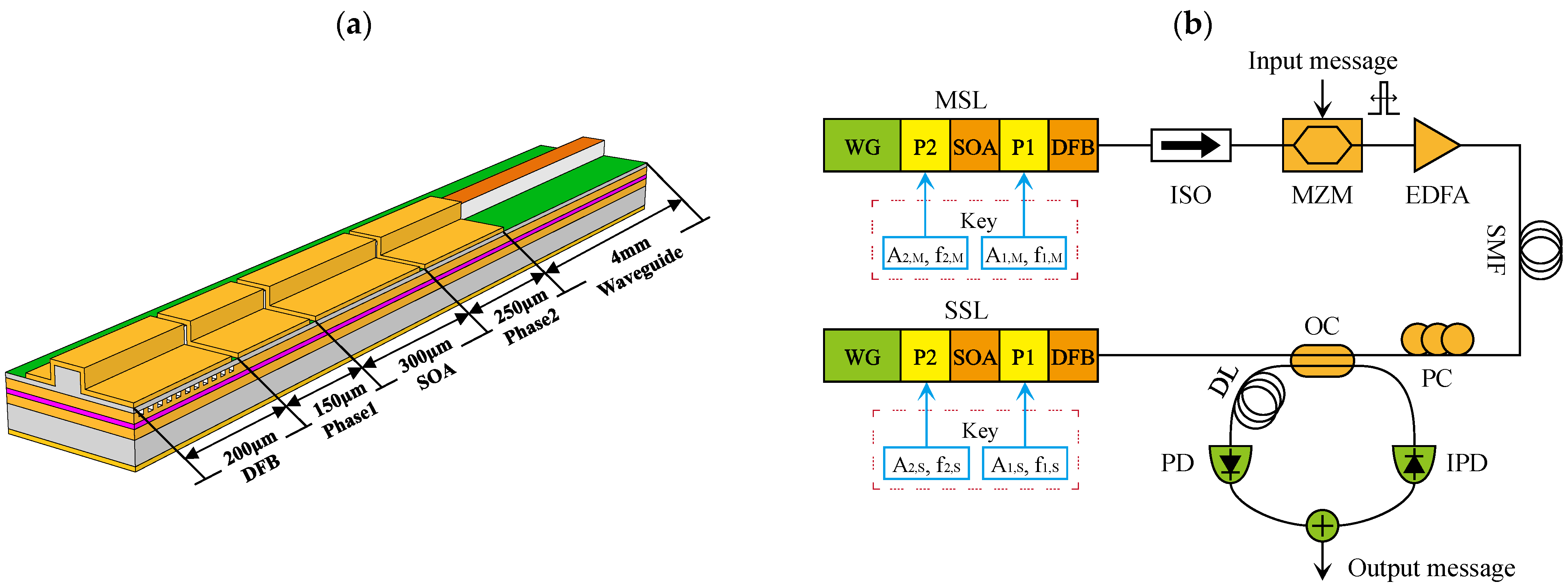
2.1. Principle
2.2. Theoretical Model
3. Results
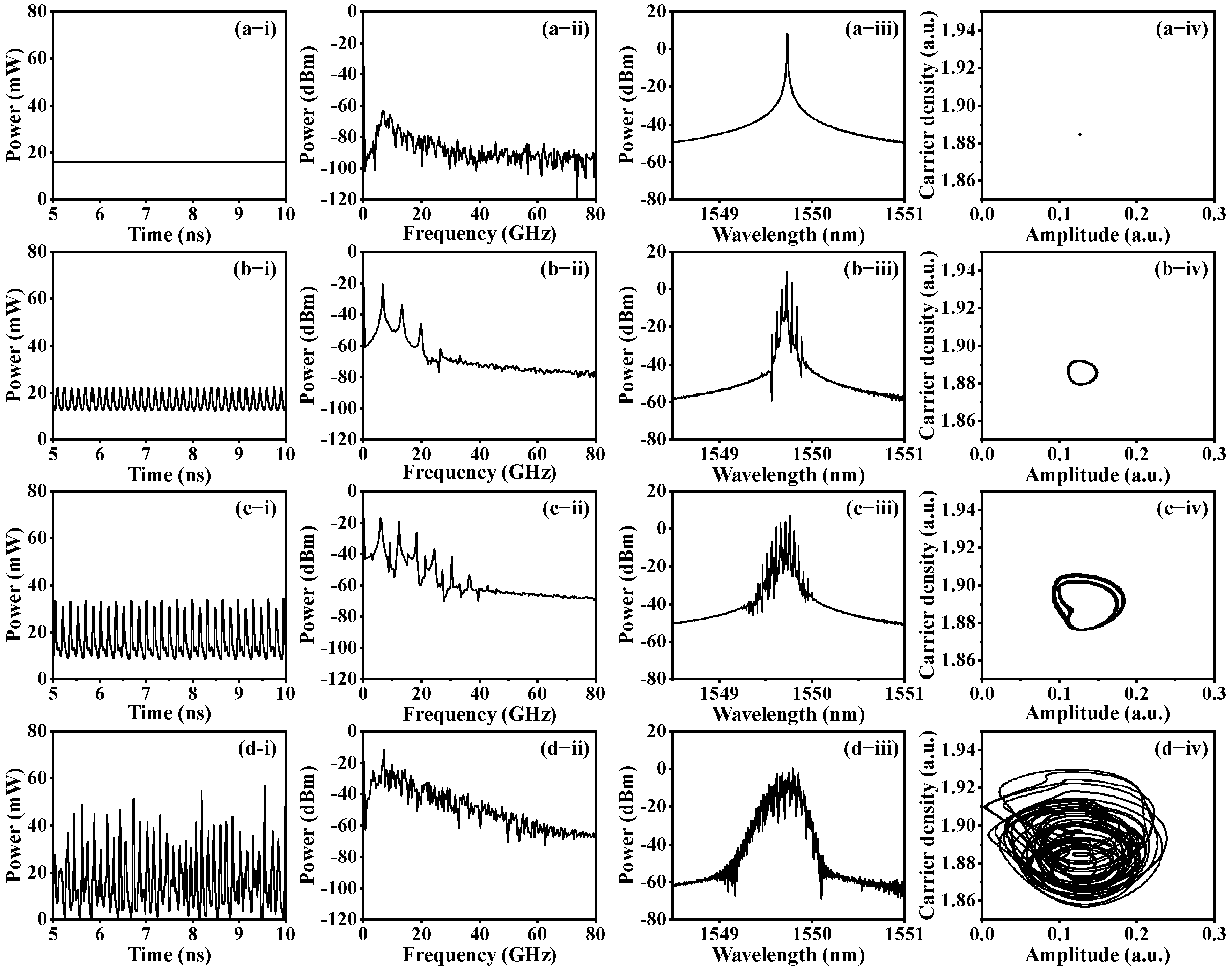
3.1. Dynamic States
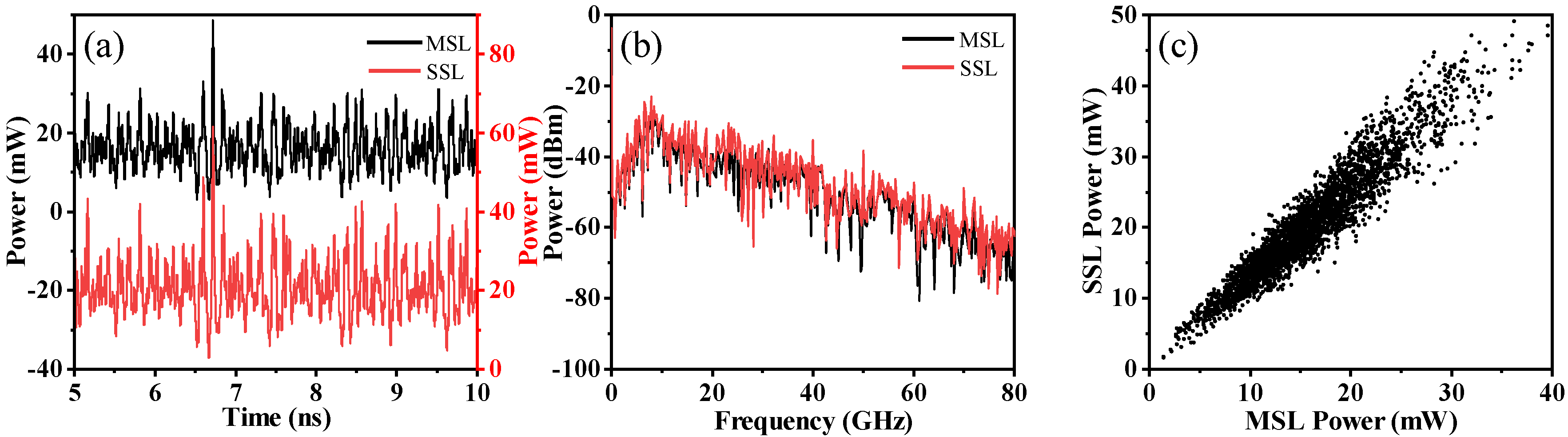
3.2. Chaos Synchronization
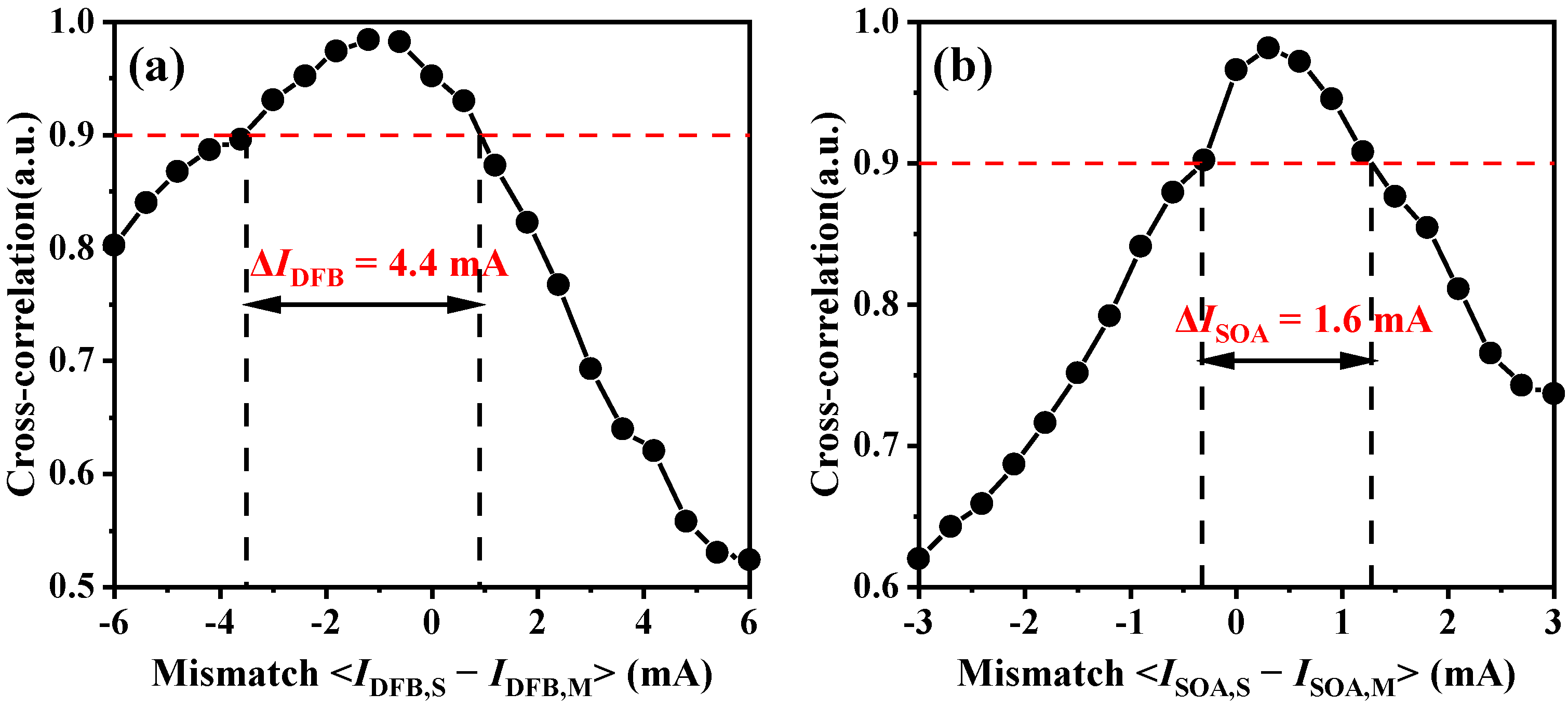
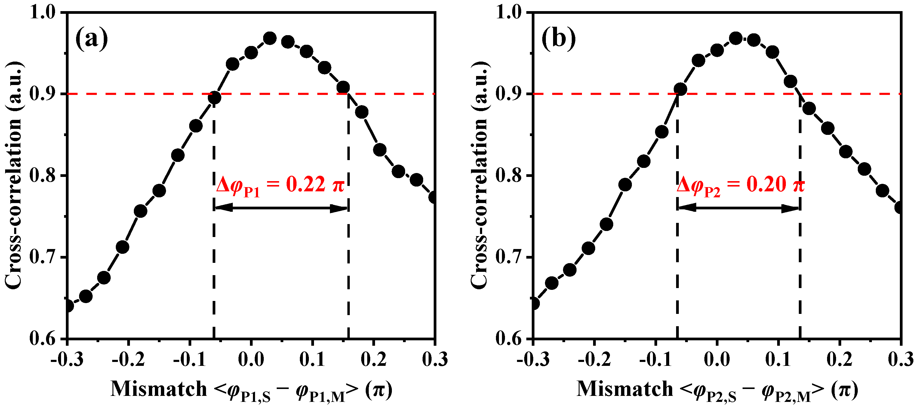
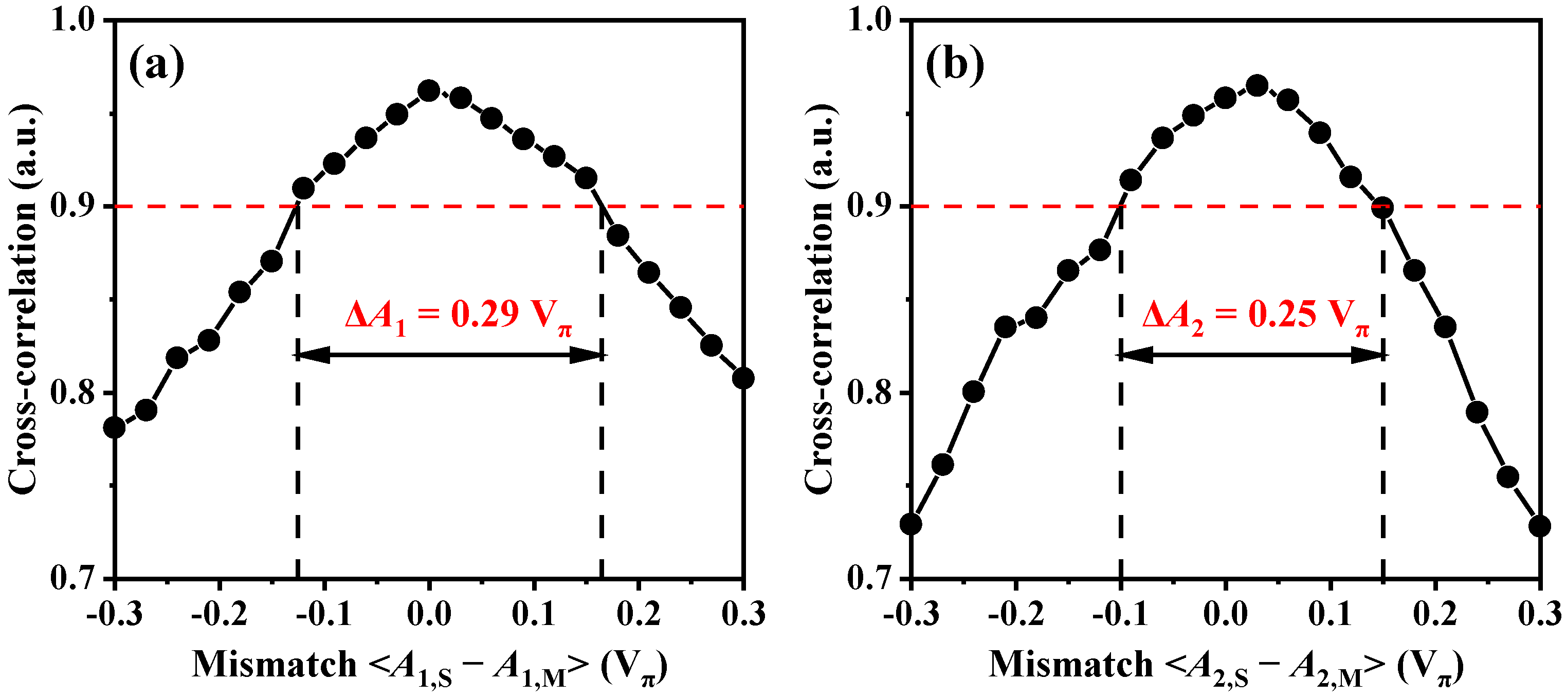
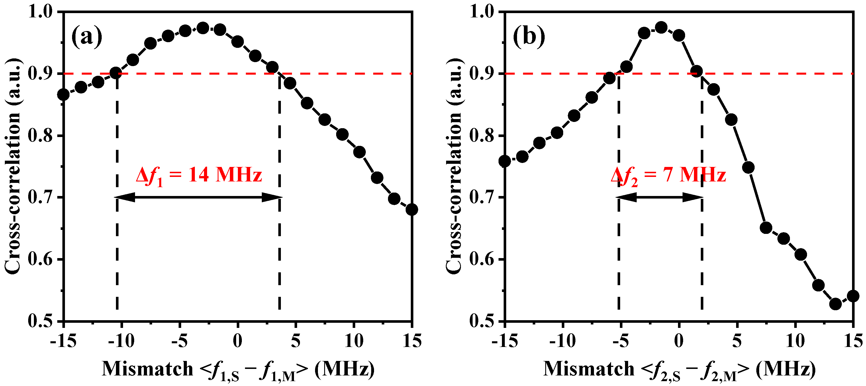
3.3. Physical Key Space Analysis
4. Discussion
5. Conclusions
Author Contributions
Funding
Institutional Review Board Statement
Informed Consent Statement
Data Availability Statement
Conflicts of Interest
References
- Pecora, L.M.; Carroll, T.L. Synchronization in chaotic systems. Phys. Rev. Lett. 1990, 64, 821. [Google Scholar] [CrossRef]
- Vanwiggeren, G.D.; Roy, R. Communication with chaotic lasers. Science 1998, 279, 1198–1200. [Google Scholar] [CrossRef] [Green Version]
- Argyris, A.; Syvridis, D.; Larger, L.; Annovazzi-Lodi, V.; Colet, P.; Fischer, I.; García-Ojalvo, J.; Mirasso, C.R.; Pesquera, L.; Shore, K.A. Chaos-based communications at high bit rates using commercial fibre-optic links. Nature 2005, 438, 343–346. [Google Scholar] [CrossRef] [PubMed]
- Huang, C.; Gao, X.; Wu, S.; Gu, W.; Su, B.; Wang, Y.; Qin, Y.; Gao, Z. Key Space Enhanced Correlated Random Bit Generation Based on Synchronized Electro-Optic Self-Feedback Loops with Mach–Zehnder Modulators. Photonics 2022, 9, 952. [Google Scholar] [CrossRef]
- Mbé, J.H.T.; Atchoffo, W.N.; Tchitnga, R.; Woafo, P. Dynamics of time-delayed optoelectronic oscillators with nonlinear amplifiers and its potential application to random numbers generation. IEEE J. Quantum Electron. 2021, 57, 1–7. [Google Scholar]
- Cui, B.; Xia, G.; Tang, X.; Wang, Y.; Wu, Z. Fast physical random bit generation based on a chaotic optical injection system with multi-path optical feedback. Appl. Opt. 2022, 61, 8354–8360. [Google Scholar] [CrossRef] [PubMed]
- Gao, Z.; Wu, S.; Deng, Z.; Huang, C.; Gao, X.; Fu, S.; Li, Z.; Wang, Y.; Qin, Y. Private correlated random bit generation based on synchronized wideband physical entropy sources with hybrid electro-optic nonlinear transformation. Opt. Lett. 2022, 47, 3788–3791. [Google Scholar] [CrossRef]
- Lin, F.Y.; Liu, J.M. Chaotic lidar. IEEE J. Sel. Top. Quantum Electron. 2004, 10, 991–997. [Google Scholar] [CrossRef]
- Wang, Y.; Zhang, M.; Zhang, J.; Qiao, L.; Wang, T.; Zhang, Q.; Zhao, L.; Wang, Y. Millimeter-level-spatial-resolution Brillouin optical correlation-domain analysis based on broadband chaotic laser. J. Lightwave Technol. 2019, 37, 3706–3712. [Google Scholar] [CrossRef]
- Zhao, T.; Han, H.; Zhang, J.; Liu, X.; Chang, X.; Wang, A.; Wang, Y. Precise fault location in TDM-PON by utilizing chaotic laser subject to optical feedback. IEEE Photonics J. 2015, 7, 1–9. [Google Scholar] [CrossRef]
- Zhang, M.; Liu, T.; Wang, A.; Zheng, J.; Meng, L.; Zhang, Z.; Wang, Y. Photonic ultrawideband signal generator using an optically injected chaotic semiconductor laser. Opt. Lett. 2011, 36, 1008–1010. [Google Scholar] [CrossRef] [PubMed]
- Bogris, A.; Rizomiliotis, P.; Chlouverakis, K.E.; Argyris, A.; Syvridis, D. Feedback phase in optically generated chaos: A secret key for cryptographic applications. IEEE J. Quantum Electron. 2008, 44, 119–124. [Google Scholar] [CrossRef]
- Xue, C.; Jiang, N.; Lv, Y.; Wang, C.; Li, G.; Lin, S.; Qin, K. Security-enhanced chaos communication with time-delay signature suppression and phase encryption. Opt. Lett. 2016, 41, 3690–3693. [Google Scholar] [CrossRef] [PubMed]
- Deng, T.; Xia, G.; Wu, Z.; Lin, X.; Wu, J. Chaos synchronization in mutually coupled semiconductor lasers with asymmetrical bias currents. Opt. Express 2011, 19, 8762–8773. [Google Scholar] [CrossRef]
- Sasaki, T.; Kakesu, I.; Mitsui, Y.; Rontani, D.; Uchida, A.; Sunada, S.; Yoshimura, K.; Inubushi, M. Common-signal-induced synchronization in photonic integrated circuits and its application to secure key distribution. Opt. Express 2017, 25, 26029–26044. [Google Scholar] [CrossRef]
- Nguimdo, R.M.; Verschaffelt, G.; Danckaert, J.; Sande, G.V. Loss of time-delay signature in chaotic semiconductor ring lasers. Opt. Lett. 2012, 37, 2541–2543. [Google Scholar] [CrossRef]
- Xiang, S.; Pan, W.; Zhang, L.; Wen, A.; Shang, L.; Zhang, H.; Lin, L. Phase-modulated dual-path feedback for time delay signature suppression from intensity and phase chaos in semiconductor laser. Opt. Commun. 2014, 324, 38–46. [Google Scholar] [CrossRef]
- Li, S.; Liu, Q.; Chan, S. Distributed feedbacks for time-delay signature suppression of chaos generated from a semiconductor laser. IEEE Photonics J. 2012, 4, 1930–1935. [Google Scholar]
- Wang, D.; Wang, L.; Zhao, T.; Gao, H.; Wang, Y.; Chen, X.; Wang, A. Time delay signature elimination of chaos in a semiconductor laser by dispersive feedback from a chirped FBG. Opt. Express 2017, 25, 10911–10924. [Google Scholar] [CrossRef] [Green Version]
- Hou, T.; Yi, L.; Yang, X.; Ke, J.; Hu, Y.; Yang, Q.; Zhou, P.; Hu, W. Maximizing the security of chaotic optical communications. Opt. Express 2016, 24, 23439–23449. [Google Scholar] [CrossRef]
- Wang, C.; Ji, Y.; Wang, H.; Bai, L. Security-enhanced electro-optic feedback phase chaotic system based on nonlinear coupling of two delayed interfering branches. IEEE Photonics J. 2018, 10, 1–15. [Google Scholar] [CrossRef]
- Argyris, A.; Hamacher, M.; Chlouverakis, K.E.; Bogris, A.; Syvridis, D. Photonic integrated device for chaos applications in communications. Phys. Rev. Lett. 2008, 100, 194101. [Google Scholar] [CrossRef] [PubMed]
- Argyris, A.; Grivas, E.; Hamacher, M.; Bogris, A.; Syvridis, D. Chaos-on-a-chip secures data transmission in optical fiber links. Opt. Express 2010, 18, 5188–5198. [Google Scholar] [CrossRef] [PubMed]
- Tronciu, V.Z.; Mirasso, C.R.; Colet, P.; Hamacher, M.; Benedetti, M.; Vercesi, V.; Annovazzi-Lodi, V. Chaos generation and synchronization using an integrated source with an air gap. IEEE J. Quantum Electron. 2010, 46, 1840–1846. [Google Scholar] [CrossRef] [Green Version]
- Harayama, T.; Sunada, S.; Yoshimura, K.; Davis, P.; Tsuzuki, K.; Uchida, A. Fast nondeterministic random-bit generation using on-chip chaos lasers. Phys. Rev. A 2011, 83, 031803. [Google Scholar] [CrossRef]
- Takahashi, R.; Akizawa, Y.; Uchida, A.; Harayama, T.; Tsuzuki, K.; Sunada, S.; Arai, K.; Yoshimura, K.; Davis, P. Fast physical random bit generation with photonic integrated circuits with different external cavity lengths for chaos generation. Opt. Express 2014, 22, 11727–11740. [Google Scholar] [CrossRef]
- Ugajin, K.; Terashima, Y.; Iwakawa, K.; Uchida, A.; Harayama, T.; Yoshimura, K.; Inubushi, M. Real-time fast physical random number generator with a photonic integrated circuit. Opt. Express 2017, 25, 6511–6523. [Google Scholar] [CrossRef]
- Wu, J.; Zhao, L.; Wu, Z.; Lu, D.; Tang, X.; Zhong, Z.; Xia, G. Direct generation of broadband chaos by a monolithic integrated semiconductor laser chip. Opt. Express 2013, 21, 23358–23364. [Google Scholar] [CrossRef]
- Yu, L.; Lu, D.; Pan, B.; Zhao, L.; Wu, J.; Xia, G.; Wu, Z.; Wang, W. Monolithically integrated amplified feedback lasers for high-quality microwave and broadband chaos generation. J. Lightwave Technol. 2014, 32, 3595–3601. [Google Scholar] [CrossRef]
- Qi, H.; Chen, G.; Lu, D.; Zhao, L. A monolithically integrated laser-photodetector chip for on-chip photonic and microwave signal generation. Photonics 2019, 6, 102. [Google Scholar] [CrossRef] [Green Version]
- Kim, B.S.; Chung, Y.; Lee, J.S. An efficient split-step time-domain dynamic modeling of DFB/DBR laser diodes. IEEE J. Quantum Electron. 2000, 36, 787–794. [Google Scholar]
- Bauer, S.; Brox, O.; Kreissl, J.; Sartorius, B.; Radziunas, M.; Sieber, J.; Wünsche, H.J.; Henneberger, F. Nonlinear dynamics of semiconductor lasers with active optical feedback. Phys. Rev. E 2004, 69, 016206. [Google Scholar] [CrossRef] [PubMed] [Green Version]
- Zhao, G.; Sun, J.; Xi, Y.; Gao, D.; Lu, Q.; Guo, W. Design and simulation of two-section DFB lasers with short active-section lengths. Opt. Express 2016, 24, 10590–10598. [Google Scholar] [CrossRef]
- Brox, O.; Bauer, S.; Radziunas, M.; Wolfrum, M.; Sieber, J.; Kreissl, J.; Sartorius, B.; Wunsche, H.J. High-frequency pulsations in DFB lasers with amplified feedback. IEEE J. Quantum Electron. 2003, 39, 1381–1387. [Google Scholar] [CrossRef]


| Parameter | Value |
|---|---|
| Central wavelength (λ0) | 1550 nm |
| Length of the DFB section (LDFB) | 200 μm |
| Length of the Phase 1 section (LP1) | 150 μm |
| Length of the SOA section (LSOA) | 300 μm |
| Length of the Phase 2 section (LP2) | 250 μm |
| Length of the waveguide (LW) | 4 mm |
| Active region thickness (d) | 0.15 μm |
| Active region width (w) | 3 μm |
| Group refractive index (ng) | 3.7 |
| Effective refractive index (neff) | 3.2 |
| Index grating coupling coefficient (ki) | 110 cm −1 |
| Gain grating coupling coefficient (kg) | 11 cm −1 |
| Linewidth enhancement factor (αH) | 4 |
| Transparency carrier density (N0) | 1.5 × 1018 cm −3 |
| Confinement factor (Γ) | 0.3 |
| Internal loss (α0) | 25 cm−1 |
| Linear recombination coefficient (A) | 3 × 10⁸ s−1 |
| Bimolecular recombination coefficient (B) | 1 × 10⁻¹⁰ cm3 s−1 |
| Auger recombination coefficient (C) | 1.3 × 10⁻²⁹ cm6 s−1 |
| Nonlinear gain saturation coefficient (ε) | 1 × 10⁻¹⁷ cm3 |
| Differential gain (gN) | 3 × 10⁻¹⁶ cm2 |
| Waveguide loss (αW) | 5 cm−1 |
| Spontaneous coupling factor (β) | 1 × 10⁻⁵ |
Disclaimer/Publisher’s Note: The statements, opinions and data contained in all publications are solely those of the individual author(s) and contributor(s) and not of MDPI and/or the editor(s). MDPI and/or the editor(s) disclaim responsibility for any injury to people or property resulting from any ideas, methods, instructions or products referred to in the content. |
© 2023 by the authors. Licensee MDPI, Basel, Switzerland. This article is an open access article distributed under the terms and conditions of the Creative Commons Attribution (CC BY) license (https://creativecommons.org/licenses/by/4.0/).
Share and Cite
Zhang, F.; Wang, Y.; Sun, Y.; Xu, J.; Li, P.; Wang, A.; Qin, Y. Key Space Enhancement in Chaotic Secure Communication Utilizing Monolithically Integrated Multi-Section Semiconductor Lasers. Photonics 2023, 10, 213. https://doi.org/10.3390/photonics10020213
Zhang F, Wang Y, Sun Y, Xu J, Li P, Wang A, Qin Y. Key Space Enhancement in Chaotic Secure Communication Utilizing Monolithically Integrated Multi-Section Semiconductor Lasers. Photonics. 2023; 10(2):213. https://doi.org/10.3390/photonics10020213
Chicago/Turabian StyleZhang, Feifan, Yuncai Wang, Yuehui Sun, Junpei Xu, Pu Li, Anbang Wang, and Yuwen Qin. 2023. "Key Space Enhancement in Chaotic Secure Communication Utilizing Monolithically Integrated Multi-Section Semiconductor Lasers" Photonics 10, no. 2: 213. https://doi.org/10.3390/photonics10020213