1. Introduction
It is now well known that visible light communication (VLC) techniques could yield numerous performance advantages, such as abundant and license-free spectrum resources, excellent transmission capacity, and inherent security [
1,
2,
3,
4]. Until now, radio frequency (RF) communication-based wireless networks have become more exhausted and restricted due to limited and expensive RF spectrum resources. Therefore, as one promising candidate solution, VLC has been envisioned and introduced to mitigate, and even overcome, the upcoming RF spectrum crisis, especially in indoor application scenarios [
5,
6,
7,
8].
For typical VLC systems, the ubiquitous light emitting diodes (LEDs)-based luminaire is utilized as the transmitter with limited hardware modification, which converts the original electrical signal to the visible optical signal via the intensity modulation (IM) scheme. On the user terminal side, the receiver equipped with the photodiode and additional concentrator module is designed to capture the optical signal from free space, and then convert the optical signal back to the electrical signal through the respective direct detection (DD) scheme [
6,
7,
8,
9]. It must be noted that, similar to the millimeter techniques, the directive propagation of the optical signal makes the VLC links sensitive and susceptible to the effects from blockage and shadowing. Once the line-of-sight (LOS) component is not available between the transmitter and the receiver, the link outage and induced performance degradation will happen with high probability. Considering the identified robustness of the conventional RF links, for improving the VLC coverage performance, the RF source, i.e., access point (AP), is suggested to be incorporated into the standalone VLC system for implementing hybrid VLC/RF transmission links [
10,
11,
12,
13,
14,
15,
16,
17,
18,
19].
In particular, the authors of [
10] addressed the interference mitigation though user association and receiver field of view (FOV) in the hybrid VLC/RF network, and potential performance gain was shown in the max–min user throughput and system throughput via two load-balancing algorithms. Moreover, the study in [
11] proposed the hybrid VLC/RF wireless scheme combining VLC, millimeter wave (mmWave), and Wireless Fidelity (WiFi) access technologies simultaneously. Accordingly, one novel convex optimization-based solution method was proposed to optimize the derived three-dimensional access point assignment problem of the hybrid VLC, mmWave, and WiFi wireless access networks, which is capable of improving the throughput-vs.-fairness trade-off compared to the conventional approaches. Similarly, the authors of [
12] investigated the combined utilization of VLC, Wireless Local Area Network (WLAN), and Long Time Evolution (LTE) for the coverage extension in an indoor environment, and identified that the above three heterogeneous technologies complement each other in the best- and even the worst-case scenarios. In addition, the work in [
13] dynamically assigned users to either the VLC or RF system, depending on the users’ channel condition. Specifically, one central unit was designed to monitor the VLC system at constant intervals, and mitigate the lower rates users to the backup RF system. At the same time, the authors of [
14] focused on investigating the energy efficiency benefits of the hybrid VLC/RF network in one heterogeneous environment and quantified the impact of the hybrid system parameters on the overall energy efficiency. In a proof-of-concept aspect, using state-of-the-art VLC and WiFi frontends, the authors of [
8] demonstrated that both technologies together could more than triple the throughput for individual users and adequately address the need for extended indoor coverage. More recently, one novel machine learning-based handover scheme was proposed for hybrid VLC and WiFi networks in [
19], which adopts one dynamic coefficient via machine learning to adjust the selection preference between VLC and WiFi links, and could enhance the user throughput performance significantly. However, almost all these relevant works assume that the concerned LEDs-based luminaires follow well-discussed Lambertian optical beam pattern characteristics, which objectively ignore the potential beam diversity and the possible relevant performance gains.
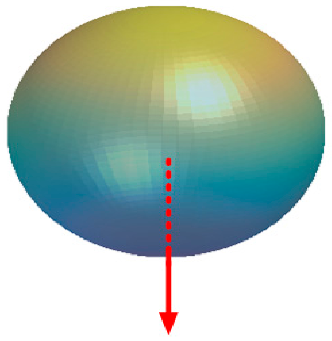
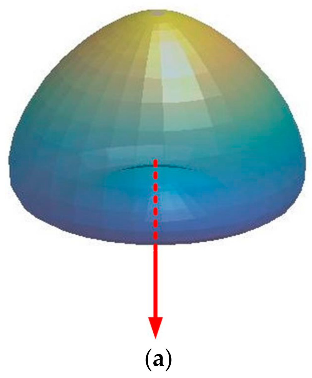
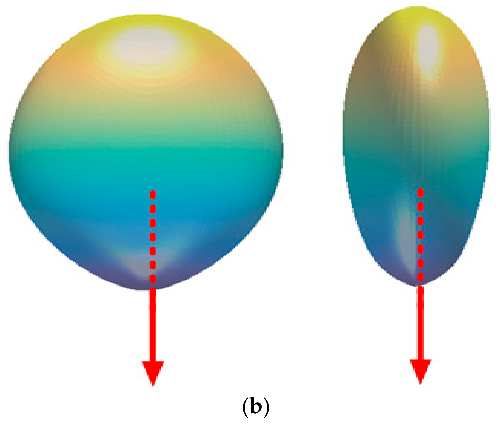
Until now, many measurement and modeling works have identified that the final optical beam generated by one LED is the sum result of three terms: the optical radiation reflected by the reflecting cup, the optical radiation refracted by the encapsulating lens, and the optical radiation internally reflected inside the lens. By flexible utilizing the above three structural factors to shape the radiation pattern of the emitting region, the distinct non-Lambertian optical beams are elaborately designed and manufactured by the international LEDs producers [
20,
21]. For the standalone VLC systems, the optical beam effect is considered and investigated in many aspects. In particular, for the first time, the authors of [
21] numerically compared the indoor VLC channel characteristics with distinct source radiation patterns, and illustrated the significantly optical beam effects on channel impulse response, optical path loss, and delay spread. On the other side, the work in [
22] extended the non-deterministic VLC channel characterization to actual radiation patterns. In addition, the works of [
23] and [
24] adopted asymmetrical emission beams to design VLC access points and construct coordinated coverage, respectively. Following this novel research paradigm, the heterogeneous optical beams were further investigated from the single input to single output (SISO) VLC systems to multiple input to multiple output (MIMO) systems systematically in [
25], which paves the way for potential combination applications of Lambertian and non-Lambertian optical beams. In addition, the authors of [
26] discussed the cells planning of VLC networks using non-circular symmetric optical beams and derived an impressive signal-to-interference-noise ratio (SINR) performance gain. Last but not least important, non-Lambertian optical beams were introduced to the VLC physical layer security issues, and the further dynamic beam configuration was proposed and evaluated as having an achievable secure transmission rate enhancement [
27,
28].
Nevertheless, to the best of our knowledge, the distinct optical beams effect, the customized design, and the potential performance gain are still waiting for fundamental discussion and numerical analysis in the hybrid VLC/RF research community. Based on the above discussion, in this work, the typical non-Lambertian beams are utilized to construct the hybrid VLC/RF transmission links. Moreover, the optical beam switchable hybrid non-Lambertian VLC/RF transmission scheme is proposed for the first time, which could provide a more spatial degree of freedom to dynamically adjust the coverage footprint for different receiver positions. The main contribution of this manuscript is focused on originally illustrating the potential effect of the distinct optical beams and opening a totally investigation dimension for the hybrid VLC/RF systems to overcome the spatial limitation induced by the conventional and well-known Lambertian beam configurations.
In this paper, the Lambertian and non-Lambertian beams characteristics are presented in
Section 2. In addition, hybrid VLC/RF channel characteristics with fixed Lambertian, fixed non-Lambertian, and switchable optical beams are investigated in
Section 3. Numerical results are presented in
Section 4, before
Section 5 concludes this paper.
3. Hybrid VLC/RF Channel Characteristics
Based on the above-described Lambertian and non-Lambertian optical beams, the relevant channel characteristics for the conventional hybrid Lambertian VLC/RF configuration, the novel hybrid non-Lambertian VLC/RF configuration, and the proposed optical beam switchable hybrid non-Lambertian VLC/RF configuration are analytically discussed and presented in this section.
3.1. Conventional Hybrid Lambertian VLC/RF Channel
In the conventional hybrid Lambertian VLC/RF transmission system, the general Lambertian LED or LED array is adopted to configure the VLC link. Accordingly, the signal received at the photodiode (PD) of the receiver is given by:
where
denotes the visible light information signal,
denotes the VLC channel direct current (DC) gain under Lambertian optical beam configuration,
R denotes the photo diode responsivity at the receiver, and
denotes the zero mean Gaussian noise.
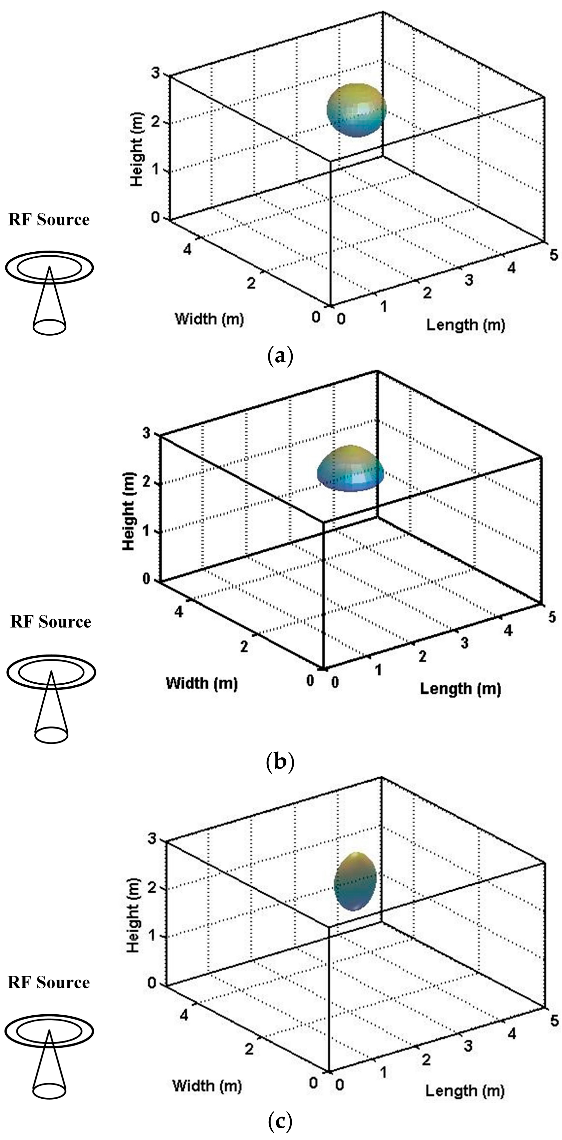
In a typical indoor scenario, one LED or LED array source with a Lambertian beam is located at the center of the ceiling, whereas the RF source is placed outside the room to construct the hybrid VLC/RF links, as shown in
Figure 3a. Since the proportion of non-line-of-sight path component is much less than the counterpart of line-of-sight path, for simplifying the analysis, this work only considers the contribution of line-of-sight path. Consequently, under the Lambertian beam configuration, the channel gain at the receiver is given as [
21,
29]:
where
denotes the detection area of the receiver,
dVLC denotes the distance between the LED source and the receiver,
denotes the angle of incidence to the receiver,
n denotes the refractive index of the optical concentrator, and
is the field of view (FOV) of the receiver. As for the RF link, the received RF signal is expressed as:
where
denotes the emitted RF signal,
denotes the received RF signal, and
denotes the RF Gaussian noise. The RF channel gain
is given as [
17]:
where
dRF denotes the separation distance between the RF source and the receiver, and
L(
dRF) denotes the RF path loss at the separation distance
dRF, which can be specifically expressed by [
17]:
where
fc denotes the carrier frequency, A, B, and C denote the constant coefficients of the RF model, and X denotes the variable dependent on the application scenario conditions. In this work, for the envisioned non-line-of-sight (NLOS) scenario with the presence of the light walls, the relevant values are set as: A = 36.8, B = 43.8, C = 20, and X = 5 [
17].
In this work, the hard switching (HS) mechanism is employed to make the selection between the candidate VLC link and the RF link. The selection criteria of HS are such that, for certain receiver locations, the candidate link which provides the maximum link throughput performance is chosen to load the traffic transmission. Thereby, for the conventional hybrid Lambertian VLC/RF transmission case, the hybrid link throughput
can be expressed by [
17]:
where
and
denote the throughputs of the individual Lambertian VLC link and individual RF link, respectively, while
and
denote the link coefficients for the above two candidate links. Both
and
can take the value of 0 or 1 to indicate the link status. For the adopted HS mechanism, only one link coefficient is permitted to take the value of 1. For instance, when
= 1 and
= 0, the Lambertian VLC link is in active status.
For the Lambertian VLC link, the respective link throughput can be derived by [
17].
where
BVLC denotes the VLC transmission bandwidth,
denotes the VLC noise variance, and
PT denotes the total emitted power in the electrical domain. Meanwhile, for the candidate RF link, the individual link throughput can be obtained as [
17]:
where
BRF denotes the RF link transmission bandwidth and
denotes the RF link noise variance.
3.2. Novel Hybrid Non-Lambertian VLC/RF Channel
Based on the above mathematical framework, once the LUXEON Rebel optical beam is leveraged to configure the hybrid VLC/RF transmission system, the envisioned application scenario should be renewed and shown in
Figure 3b. In this situation, the signal received at PD of the receiver is given by:
where
denotes the VLC channel DC gain under the LUXEON Rebel optical beam configuration, which can be expressed as follows:
where
denotes the power normalization factor of the LUXEON Rebel optical beam, which functions to ensure that the beam power radiated in all spatial directions is 1 W. In other words, unlike the conventional Lambertian beam pattern, this non-Lambertian beam pattern fails to realize the natural normalization since it is derived from the numerical fitting of measurement data of the commercially available LED product.
Similarly, as for the asymmetric NSPW optical beam case, the signal captured at the VLC receiver is expressed by:
where
denotes the VLC channel DC gain under asymmetric NSPW optical beam configuration, which can be given as follows:
where
denotes the power normalization factor of the NSPW optical beam. In addition, for this asymmetric NSPW optical beam case, the envisioned application scenario is renewed and shown in
Figure 3c.
Straightforwardly, referring to Equation (10) of the conventional hybrid Lambertian VLC/RF case, the hybrid link throughput for the above two hybrid non-Lambertian VLC/RF cases can be given separately as follows:
where
and
denote the link coefficients for the LUXEON Rebel VLC link and the NSPW VLC link, respectively, while
and
denote the link throughputs for these two non-Lambertian VLC link options, respectively. In particular,
and
can be identified by the following two expressions:
3.3. Optical Beam Switchable Hybrid Non-Lambertian VLC/RF Channel
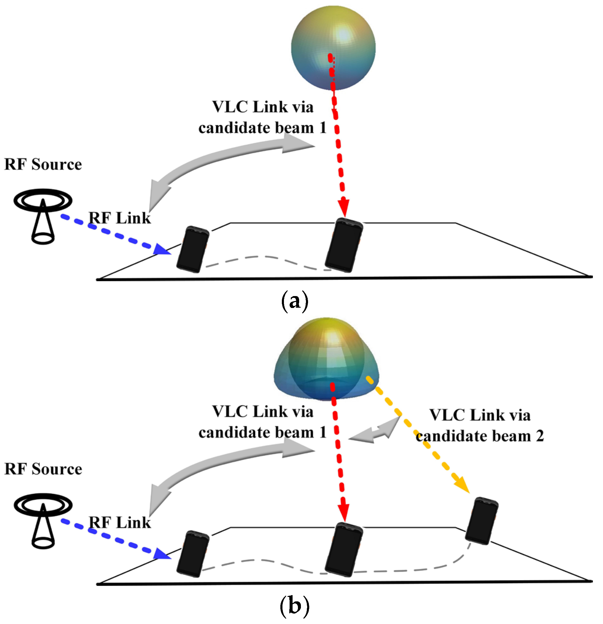
No matter that the above Lambertian or non-Lambertian optical beams are utilized to construct the hybrid VLC/RF transmission system, it is assumed that at the VLC transmitter, the available optical beams are of the same pattern or there is only one available optical beam, which implies that the VLC transmitter is composed of a single high-power LED or a homogeneous LED array. Furthermore, the indoor hybrid VLC/RF link switching illustration with one candidate optical beam or homogeneous optical beams is shown in
Figure 4a.
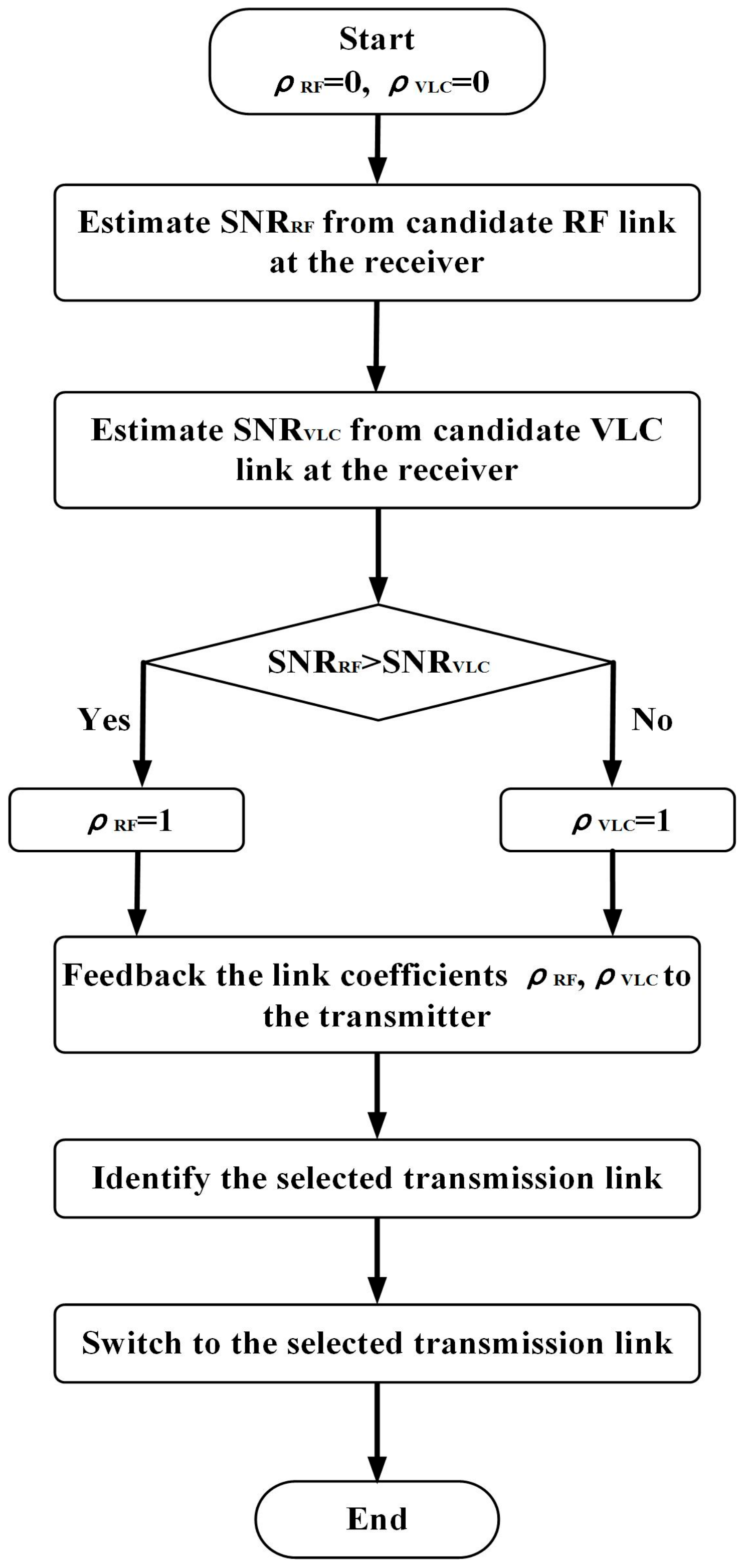
The operation mechanism of the homogeneous optical beams-based hybrid VLC/RF hard switching scheme can be summarized as follows: firstly, the receiver estimates the signal-to-noise ratio (SNR) from the candidate RF link, i.e., SNRRF; secondly, the receiver estimates the SNR from the candidate VLC link, i.e., SNRVLC; thirdly, the comparison is made between the estimated two SNRs. If SNRRF > SNRVLC, is set as 1, otherwise is set as 1. The receiver then feedbacks the link coefficients and to the hybrid VLC/RF transmitter; then, according to the values of and , the transmitter identifies the selected transmission link. Finally, the transmitter switches to the selected candidate link.
On the other side, if the VLC transmitter is composed of multiple heterogeneous LEDs or heterogeneous LED subarrays, there is more than one available optical beam or the available optical beams are of different patterns at the VLC transmitter. As such, the heterogeneous optical beams’ configuration provides the additional VLC candidate link for enhancing a hard switching degree of freedom (DOF). Intuitively, the indoor hybrid VLC/RF link switching illustration with heterogeneous optical beams is shown in
Figure 4b.
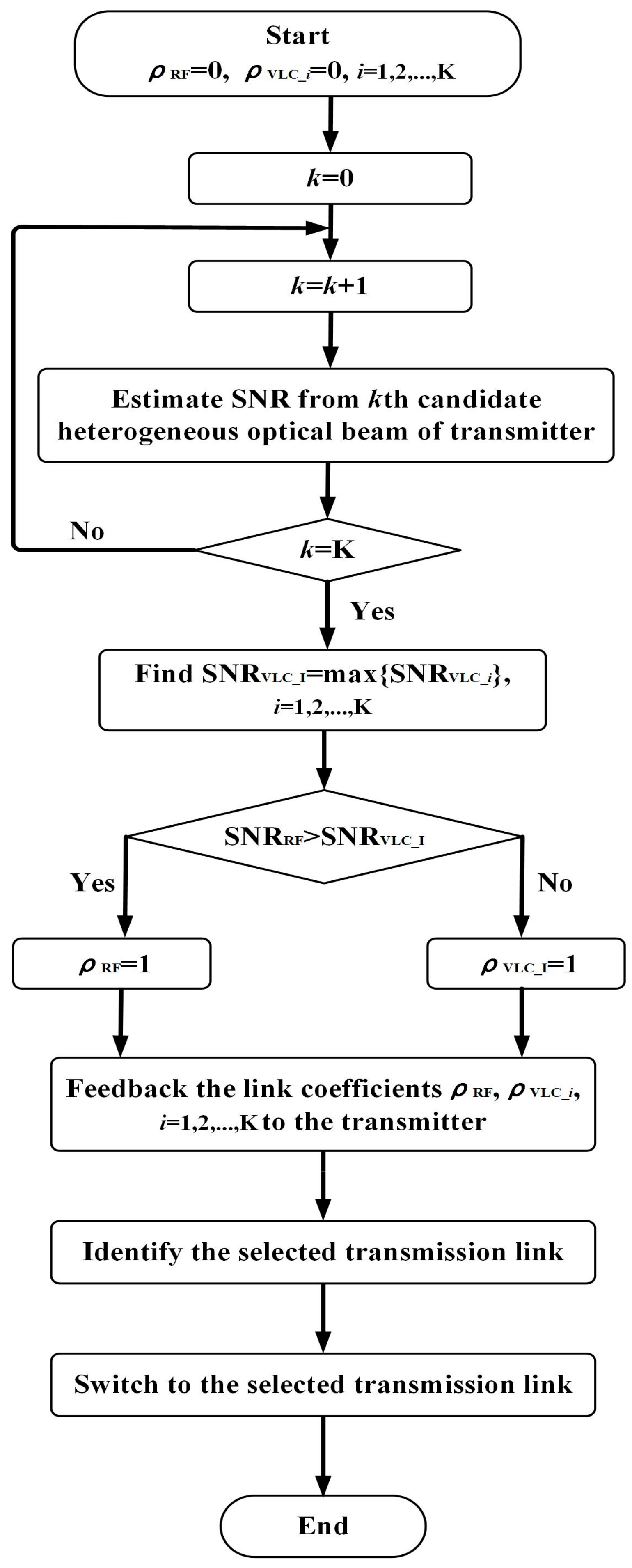
Utilizing this additional DOF, the optical beam switchable hybrid non-Lambertian VLC/RF configuration scheme is proposed. In this scheme, the relevant operation mechanism can be summarized as follows: firstly, K heterogeneous optical beams are available at the transmitter and both the RF and VLC link coefficients are set as 0 at the receiver; the receiver in turn then estimates the SNR from each candidate optical beam and identifies the maximum SNR, i.e., SNRVLC_I and the associated candidate optical beam I. The comparison is then made between the estimated SNRVLC_I and SNRRF. If SNRRF >SNRVLC_I, is set as 1; otherwise, is set as 1, where denotes the VLC link coefficient of the Ith heterogeneous optical beam. The receiver then feedbacks all the K VLC link coefficients and to the hybrid VLC/RF transmitter; then, according to the values of and , the transmitter identifies the selected transmission link. Finally, the transmitter switches to the selected candidate link.
For the above homogeneous optical beams’ configuration, the flow chart of the hybrid VLC/RF hard switching scheme is shown in
Figure 5. In addition, for this heterogeneous optical beams’ configuration, the respective flow chart of this hard switching scheme is illustrated in
Figure 6. It should be noted that in the proposed operation mechanism, the electrical domain SNR at the receiver is utilized as the performance metric to guide the link hard switching.
For convenience of analysis, three heterogeneous optical beams combinations are considered in this work. In particular, the three combinations are based on: (1) heterogeneous Lambertian optical beam and LUXEON Rebel optical beam, (2) heterogeneous Lambertian optical beam and asymmetric NSPW optical beam, and (3) heterogeneous LUXEON Rebel optical beam and asymmetric NSPW optical beam. Accordingly, the above three heterogeneous optical beams combination-based hybrid link throughputs are presented as follows:
The implication for the practical implementation is that the respective independent LED modules or subarrays which follow distinct optical radiation patterns must be incorporated into the VLC transmitter, such that the distinct candidate optical beams are available for the proposed operation mechanism.
4. Numerical Evaluation
In this section, the numerical evaluation is made between the conventional hybrid Lambertian VLC/RF configuration, the novel hybrid non-Lambertian VLC/RF configuration, and the proposed optical beam switchable hybrid non-Lambertian VLC/RF configuration in transmission throughput performance.
Specifically, one typical medium-size room is considered, which is consistent with
Figure 3. In addition, the involved main parameters are included in
Table 1.
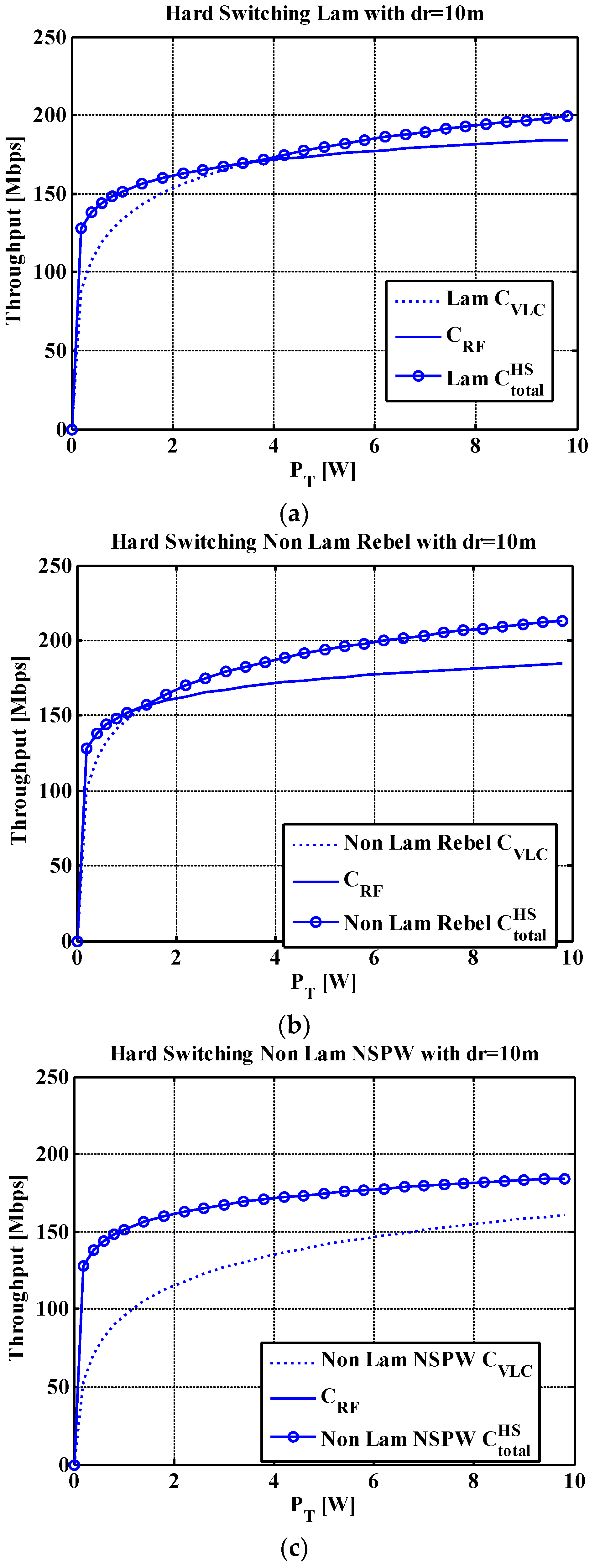
In most hybrid VLC/RF application scenarios, the hard switching is liable to be executed at the VLC coverage edge area, since the optical signal usually experiences more spatial dispersion and a longer propagation path to reach the destination receiver. Therefore, one typical edge receiver location, i.e., (4.3, 4.3, 0.85) m, is chosen to make a hybrid link throughput comparison versus total available power among the conventional Lambertian and two employed representative non-Lambertian optical beams. Assume that the distance between the involved RF source and the receiver is 10 m, and that there are light walls separating the RF source and the receiver.
As shown in
Figure 7a, for the Lambertian optical beam configuration, the VLC link could not provide higher throughput until the total available power reached approximately 4 W at the transmitter. As for the LUXEON Rebel non-Lambertian optical beam configuration, as shown in
Figure 7b, once the total available power reaches approximately 1 W at the transmitter, the hard switching is made to the VLC link to achieve better throughput performance, which means that superior energy efficiency is provided to this edge target receiver via the LUXEON Rebel optical beam, compared to the counterpart of the Lambertian optical beam. Furthermore, for the last case of asymmetric NSPW optical beam configuration, for almost all the total available power range, the VLC link is consistently in active status, which indicates that excellent energy efficiency is achieved by this asymmetric non-Lambertian optical beam, even if the receiver is located at or close to the edge of the coverage area, as shown in
Figure 7c.
For the sake of clarity, the RF link throughput spatial distribution for this typical indoor scenario is illustrated in
Figure 8. For the convenience of discussion, the separation between the RF source and the VLC transmitter is 10 m. Thereby, quite uniform throughput distribution can be provided by the RF link, even for the corner or edge positions, due to multipath dispersion RF propagation properties. Moreover, the relevant throughput distribution ranges between 139.06 and 166.02 Mbps, with the average throughput approximately 151.44 Mbps.
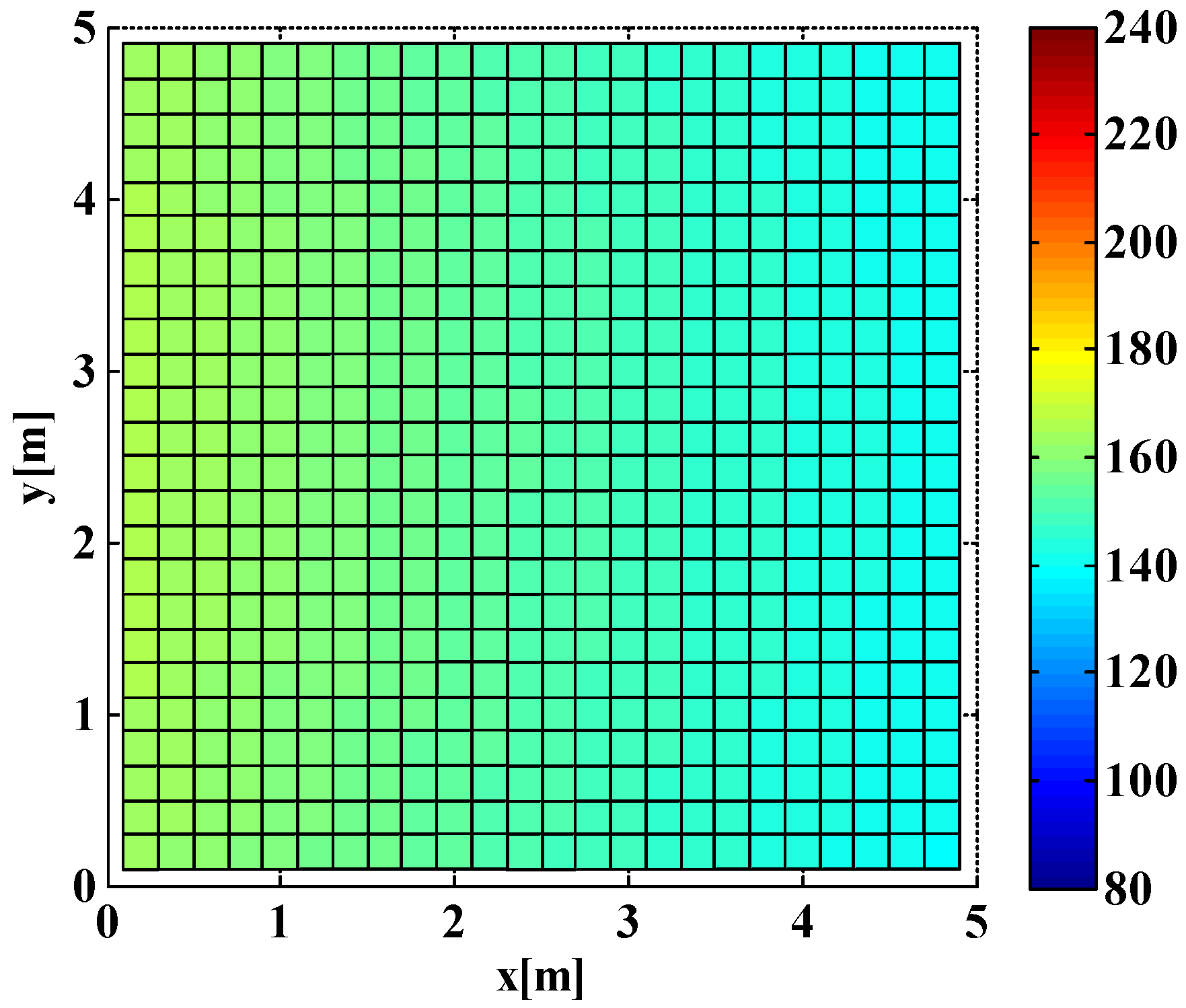
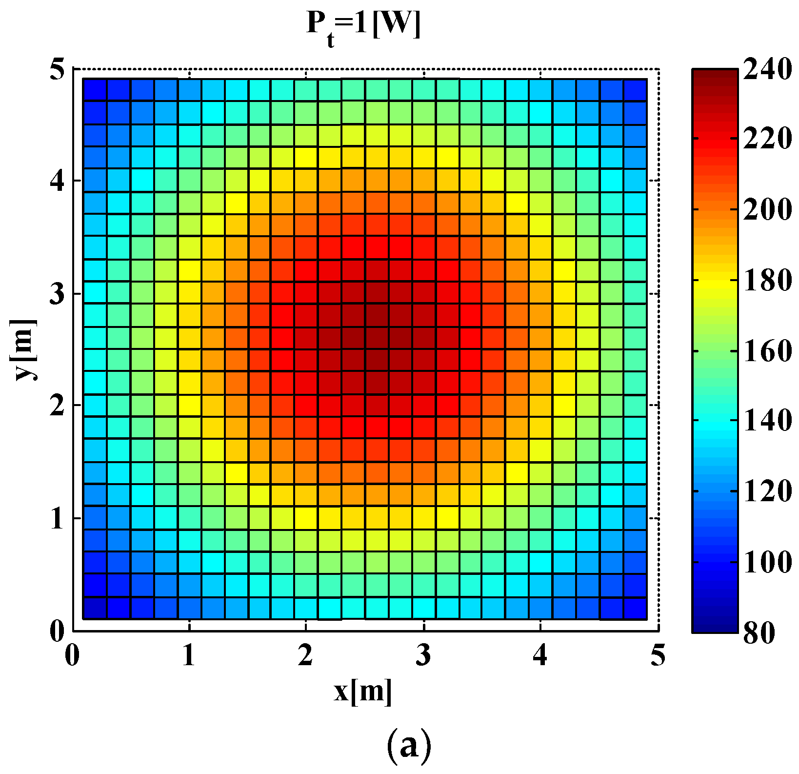
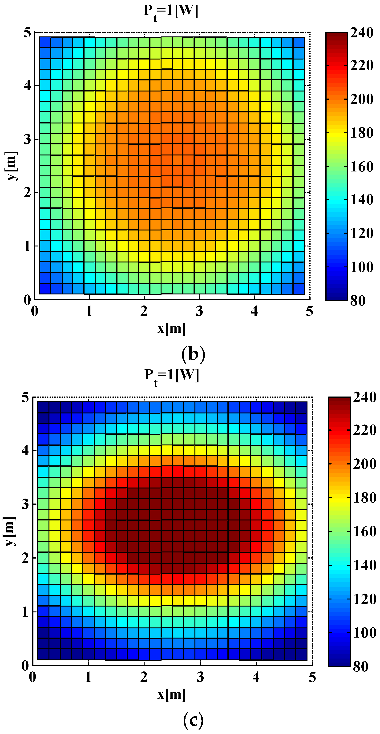
For the individual VLC link, the throughput distribution is shown in
Figure 9. For the Lambertian optical beam configuration, the obvious circular coverage footprint appears around the central VLC transmitter position, while apparent weak coverage appears close to the corner locations, as shown in
Figure 9a. The respective throughput distribution ranges between 91.30 and 234.39 Mbps, with the average throughput approximately 165.70 Mbps. A similar distribution appears for the VLC throughput under the LUXEON Rebel optical beam configuration, with the difference being that more uniform coverage appears within the central circular footprint, as shown in
Figure 9b. Correspondingly, the throughput distribution ranges between 101.33 and 203.39 Mbps, with the average throughput approximately 170.69 Mbps. As for the case of the individual VLC link with the NSPW optical beam configuration, the original circular central footage is replaced by the elliptical one, as shown in
Figure 9c, which is dominated by the asymmetric spatial radiation pattern of this non-Lambertian beam. Respectively, the throughput distribution ranges between 59.01 and 279.34 Mbps, with the average throughput approximately 165.21 Mbps, while the weaker coverage area appears at the room corners.
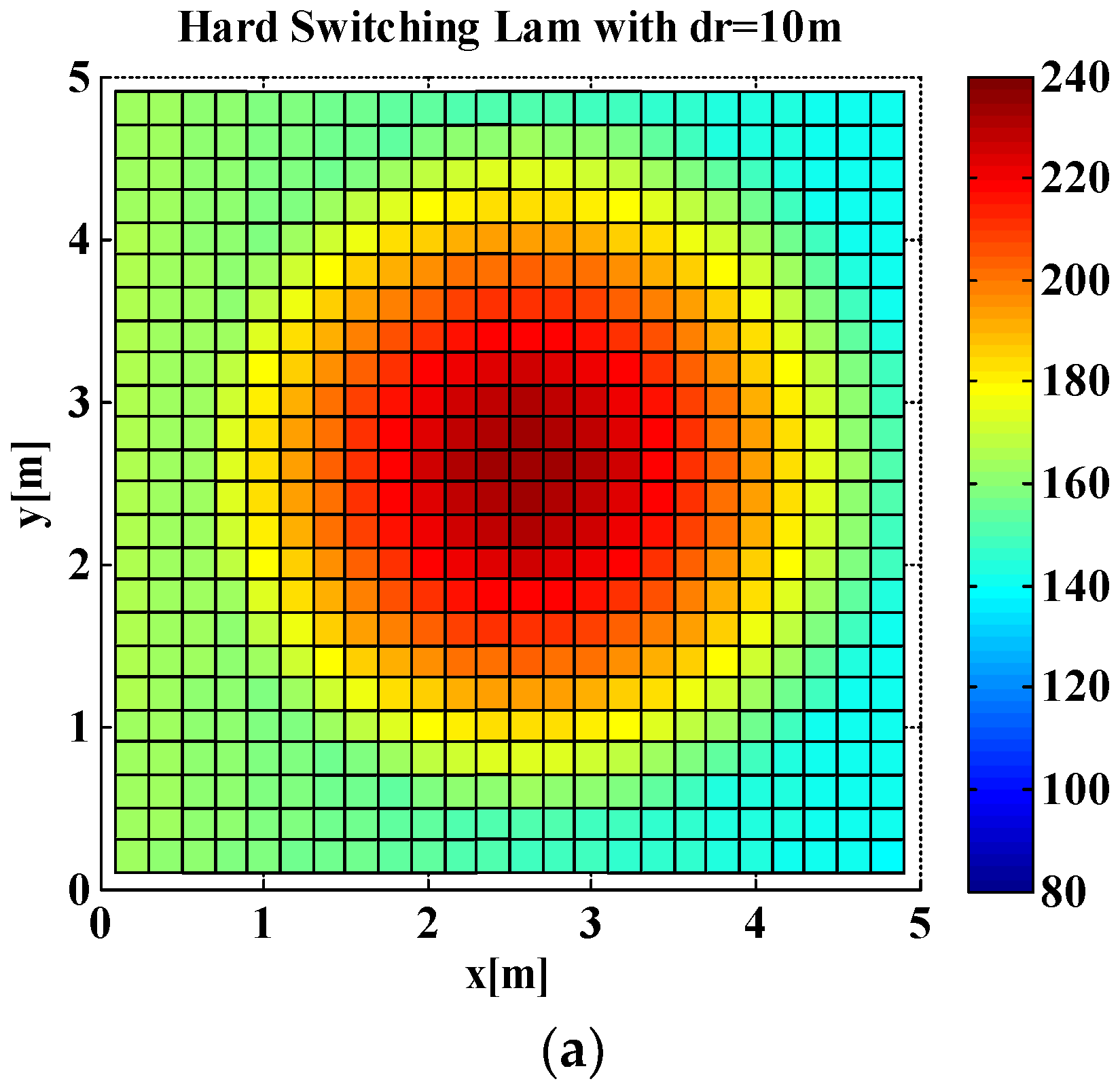
In
Figure 10, the hybrid VLC/RF link throughput spatial distributions for the concerned three optical beam configurations are presented separately. Since the better throughput is available from the backup RF link, the weak coverage issue, especially at the room corners, is significantly proved. Specifically, for the Lambertian optical beam configuration, the hybrid VLC/RF link throughput distribution ranges between 139.06 and 234.39 Mbps, with the average throughput enhanced to approximately 174.14 Mbps, as presented in
Figure 10a. As for the LUXEON Rebel optical beam configuration, the hybrid link throughput distribution lies between 139.06 and 203.39 Mbps, with the average throughput enhanced to approximately 175.10 Mbps, as presented in
Figure 10b. Thirdly, for the hybrid link with asymmetric NSPW optical beam configuration, the throughput distribution lies between 139.06 and 279.34 Mbps, with the average throughput enhanced to approximately 181.47 Mbps, as presented in
Figure 10c. Compared to the initial Lambertian hybrid VLC/RF link, the gain of maximum throughput is up to 44.95 Mbps, while the gain of average throughput is up to 7.33 Mbps.
In
Figure 11, the CDFs of the hybrid VLC/RF link throughput spatial distribution for the concerned three optical beam configurations are illustrated separately. In all three cases, the high throughput portion of the CDF curve of the hybrid VLC/RF link is basically consistent with the CDF curve of the individual VLC link, while the left low throughput portion of the CDF curve of the hybrid VLC/RF link is closer to the CDF curve of the individual RF link. In particular, for the Lambertian hybrid VLC/RF case, the percentage of throughput less than 160 Mbps is approximately 33.60%, as presented in
Figure 11a, while the counterpart of the non-Lambertian LUXEON Rebel hybrid VLC/RF case is reduced by approximately 22.56%, as shown in
Figure 11b. Moreover, this metric can be further increased to 38.72% once the asymmetric NSPW optical beam is adopted at the VLC transmitter, as shown in
Figure 11c.
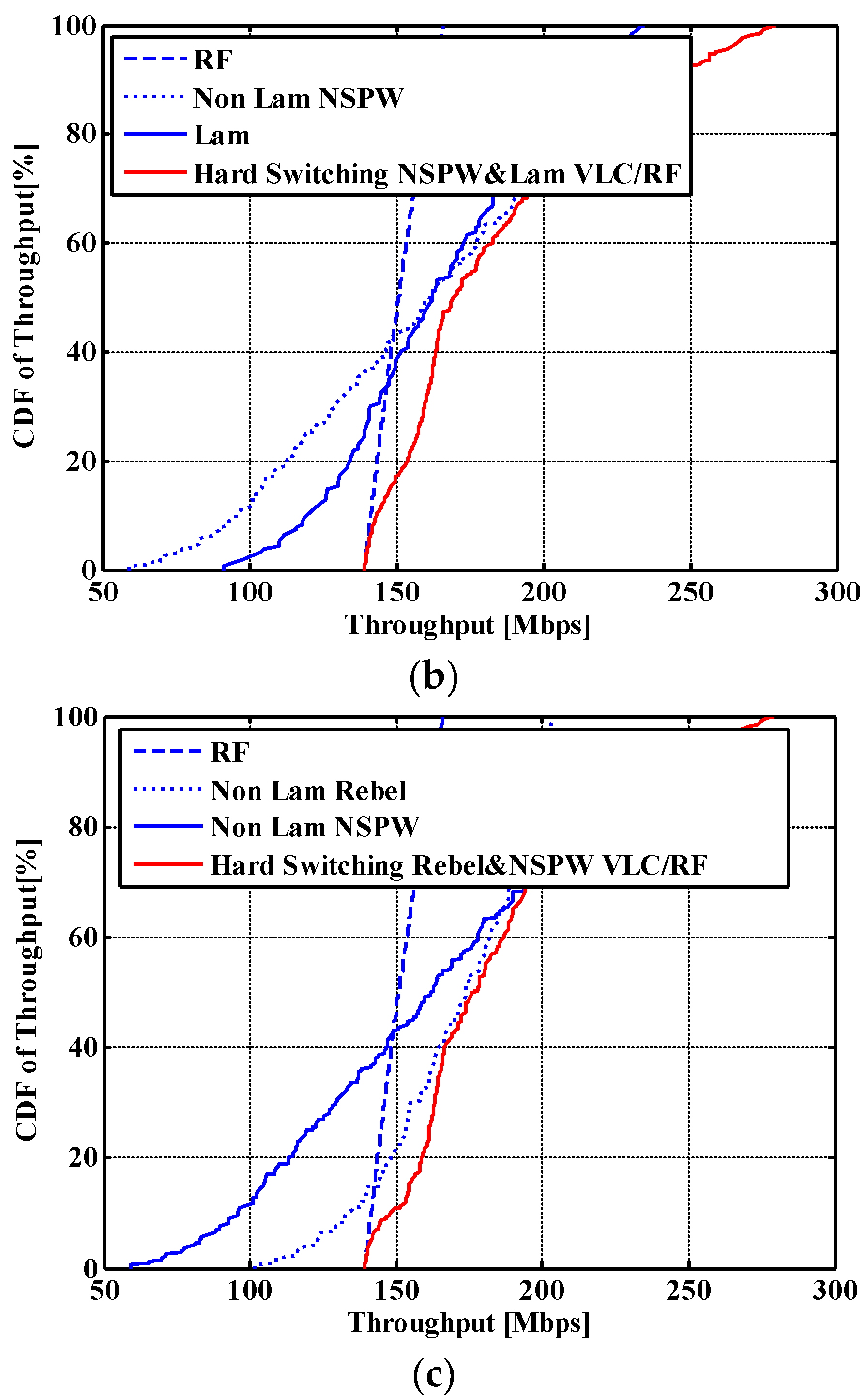
Finally, for the proposed heterogeneous optical beams-based hybrid VLC/RF link configurations, the relevant CDF of the throughput spatial distribution is illustrated in
Figure 12. For the configuration of the heterogeneous Lambertian optical beam and LUXEON Rebel optical beam, the CDF of the hybrid link outperforms that of the candidate Lambertian VLC link and the candidate Rebel non-Lambertian VLC link. Specifically, for this switchable heterogeneous Lambertian and asymmetric NSPW optical beam configuration, the CDF of the hybrid link throughput spatial distribution ranges between 139.06 and 234.39 Mbps, with the average throughput increased to approximately 178.38 Mbps. As shown in
Figure 12a, the percentage of hybrid link throughput less than 160 Mbps is approximately 22.56%. Then, for the configuration of heterogeneous Lambertian optical beam and asymmetric NSPW optical beam, the CDF of the hybrid link throughput distribution ranges between 139.06 and 279.34 Mbps, with the average throughput further increased to approximately 183.75 Mbps. Respectively, the percentage of hybrid link throughput less than 160 Mbps is approximately 31.04%, as shown in
Figure 12b. On the other side, for the left configuration of the heterogeneous LUXEON Rebel optical beam and asymmetric NSPW optical beam, the excellent coverage performance can be identified from several key metrics. In particular, the relevant CDF of the hybrid link throughput distribution ranges between 139.06 and 279.34 Mbps, with the average throughput up to approximately 186.45 Mbps, while the percentage of hybrid link throughput less than 160 Mbps is reduced to approximately 22.56% simultaneously. Compared to the benchmark hybrid VLC/RF link with the mere Lambertian optical beam, this proposed heterogeneous optical beams-based hybrid VLC/RF link configuration is capable of providing 7.07% average throughput gain, and approximately 11.04% reduction of locations with throughput less than 160 Mbps at the same time.


