Rate-Splitting-Based Generalized Multiple Access for Band-Limited Multi-User VLC


Abstract
:1. Introduction
1.1. Related Work and Motivation
1.1.1. Orthogonal Multiple Access
1.1.2. Non-Orthogonal Multiple Access
1.1.3. Rate-Splitting Multiple Access
1.1.4. Summary
1.2. Main Contributions
- Proposal of a rate-splitting-based GMA scheme for band-limited multi-user VLC systems, which can be seen as a generalized version of OFDMA and NOMA;
- Derivation of the theoretical achievable rate of a general band-limited two-user VLC system applying rate-splitting-based GMA under the impact of both the LED’s low-pass frequency response and the imperfect SIC-induced error propagation;
- Optimization of the rate-splitting-based GMA scheme to maximize the overall achievable rate of the band-limited two-user VLC system;
- Evaluation of the obtained optimal rate-splitting-based GMA scheme and other benchmark schemes in a practical band-limited two-user VLC system through extensive computer simulations and hardware experiments.
2. System Model
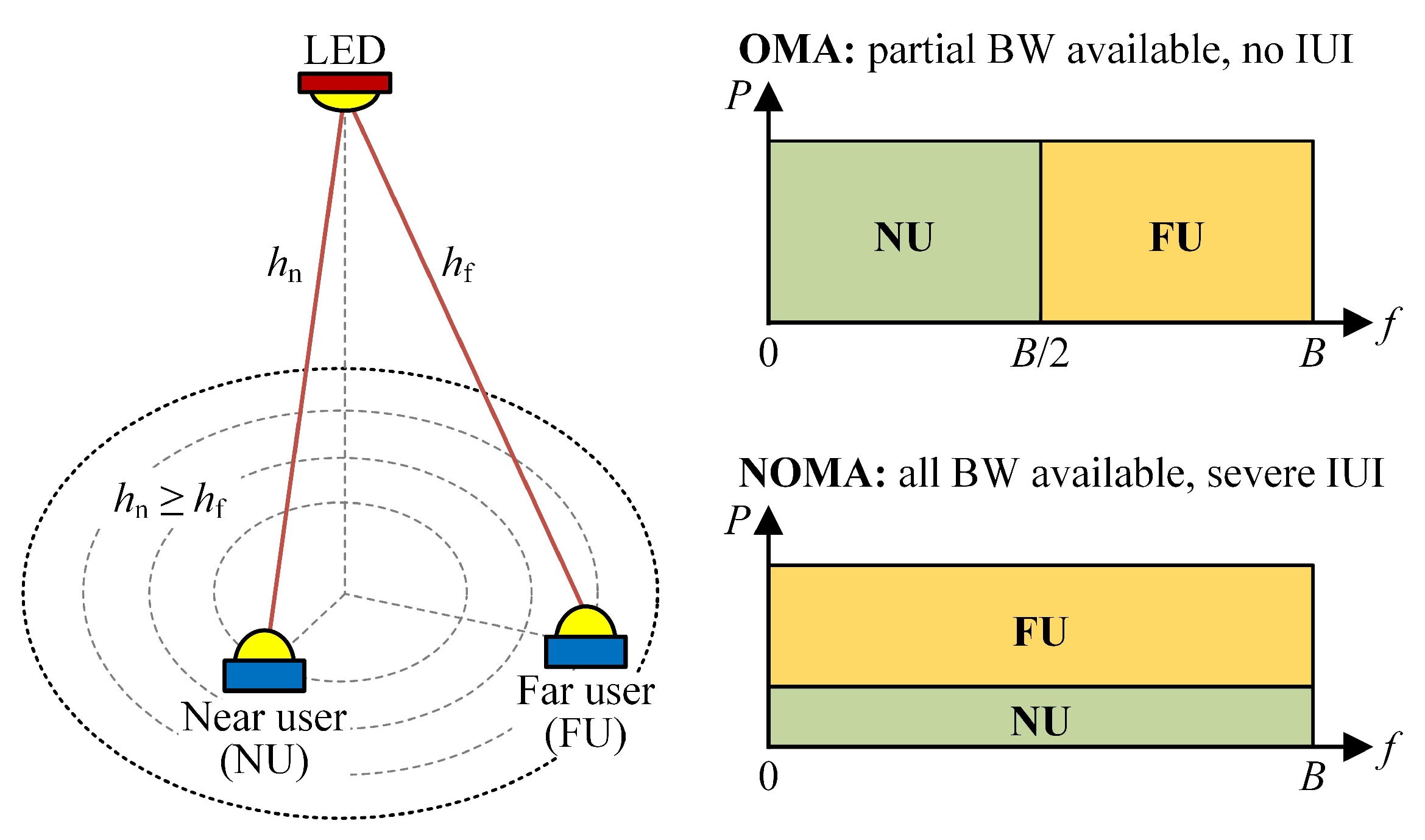
2.1. Channel Model
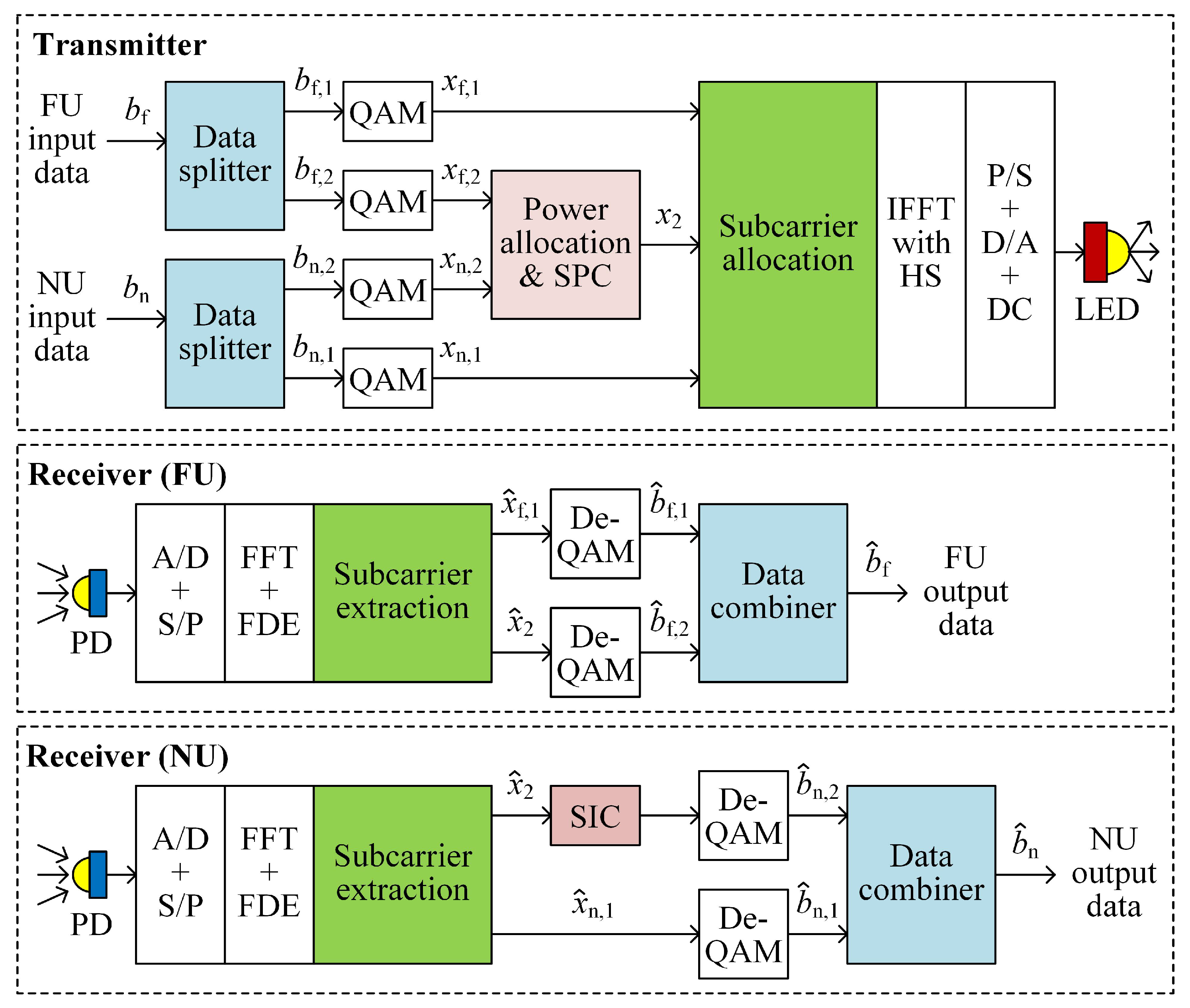
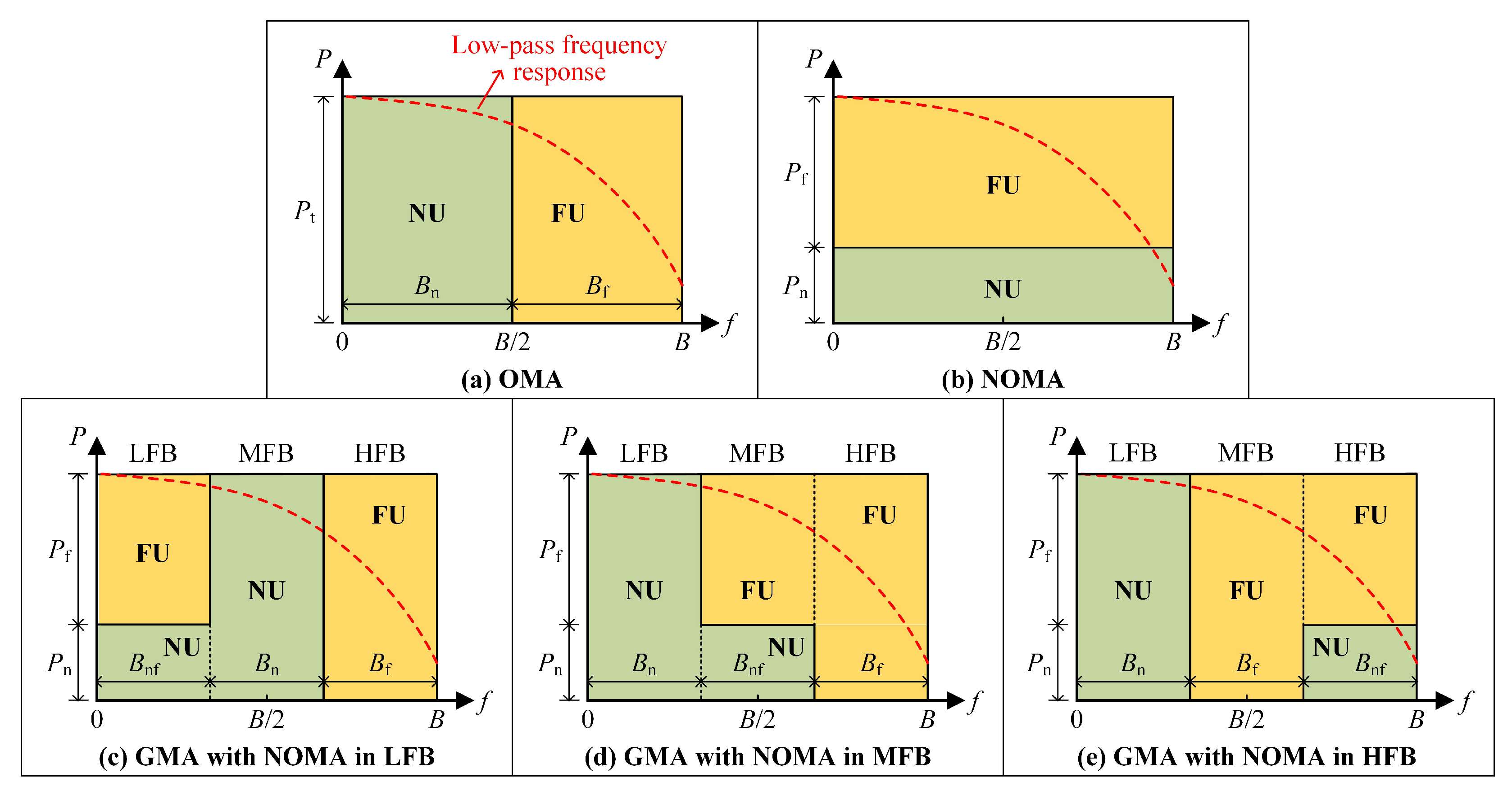
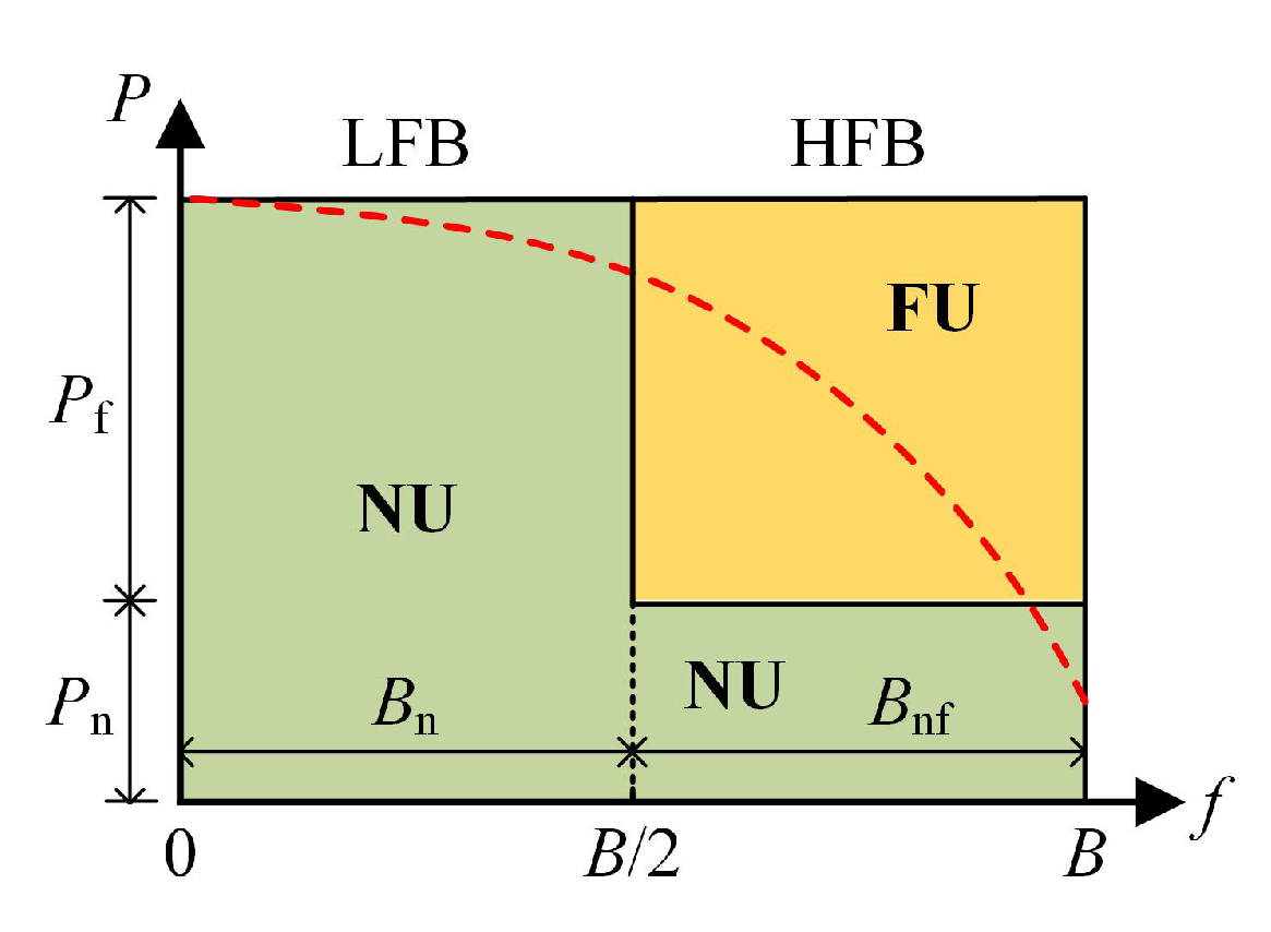
2.2. Principle of Rate-Splitting-Based GMA
2.3. Achievable Rate
3. Results and Discussion
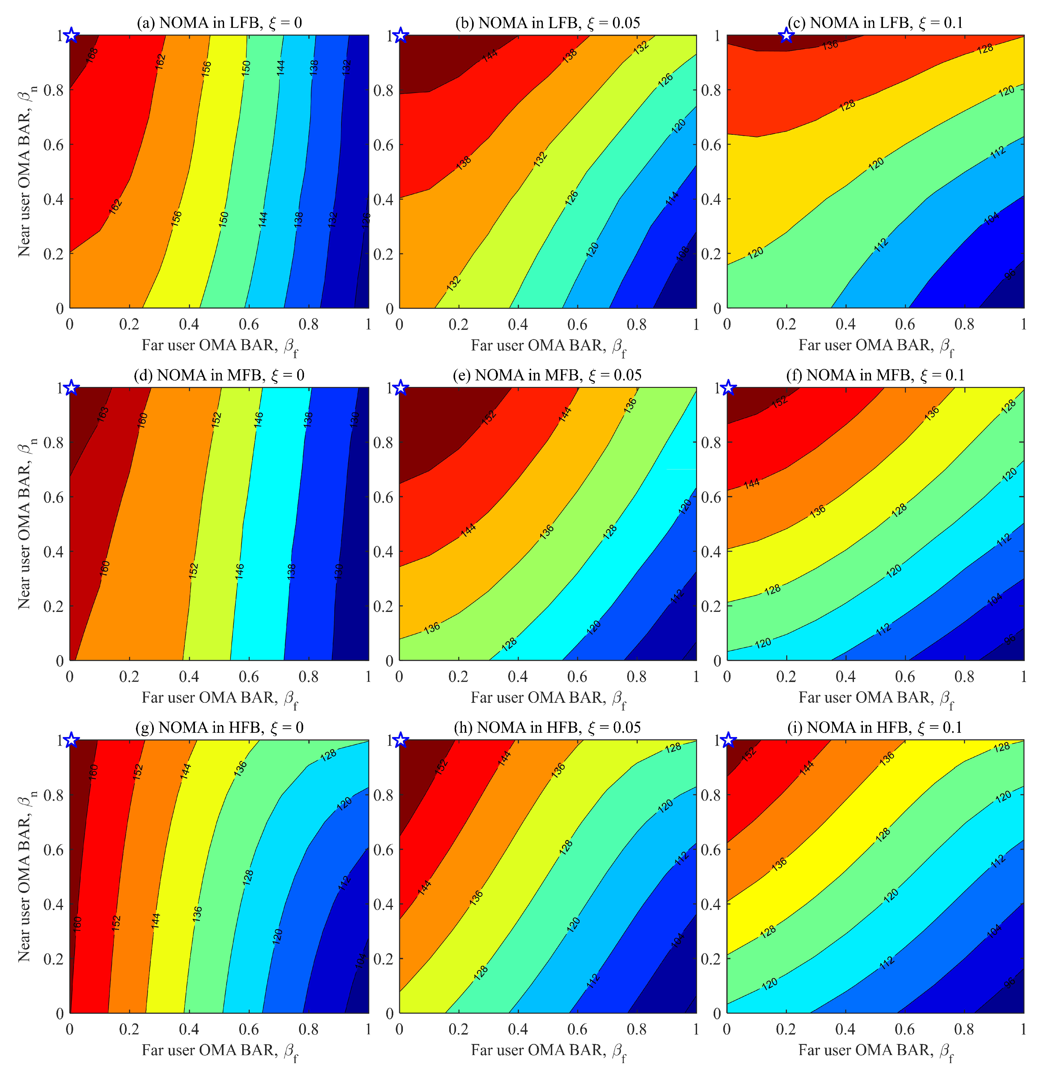
3.1. Optimization of Rate-Splitting-Based GMA Schemes
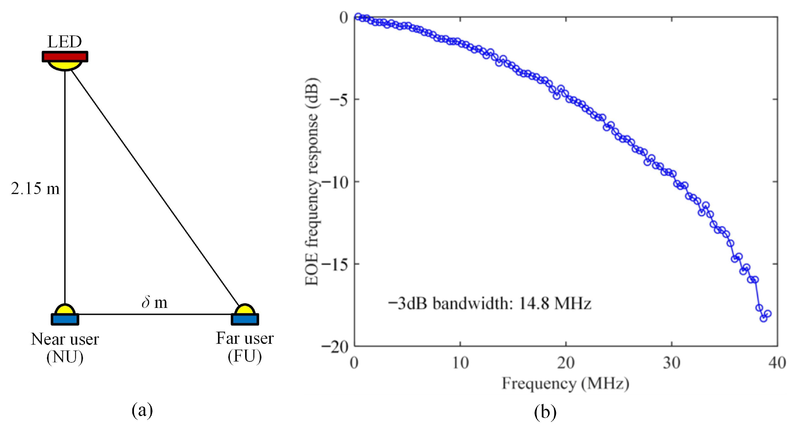
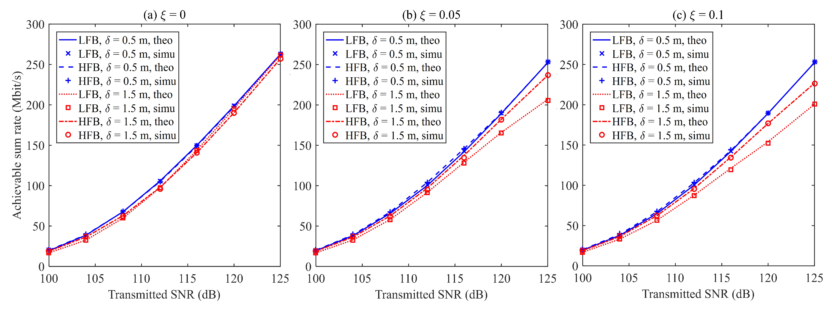
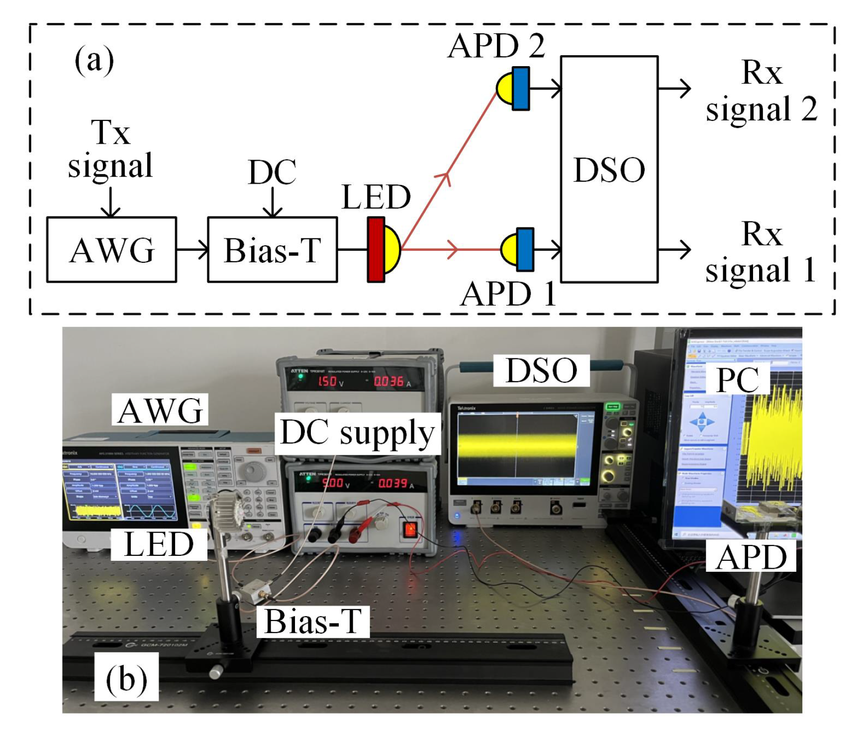
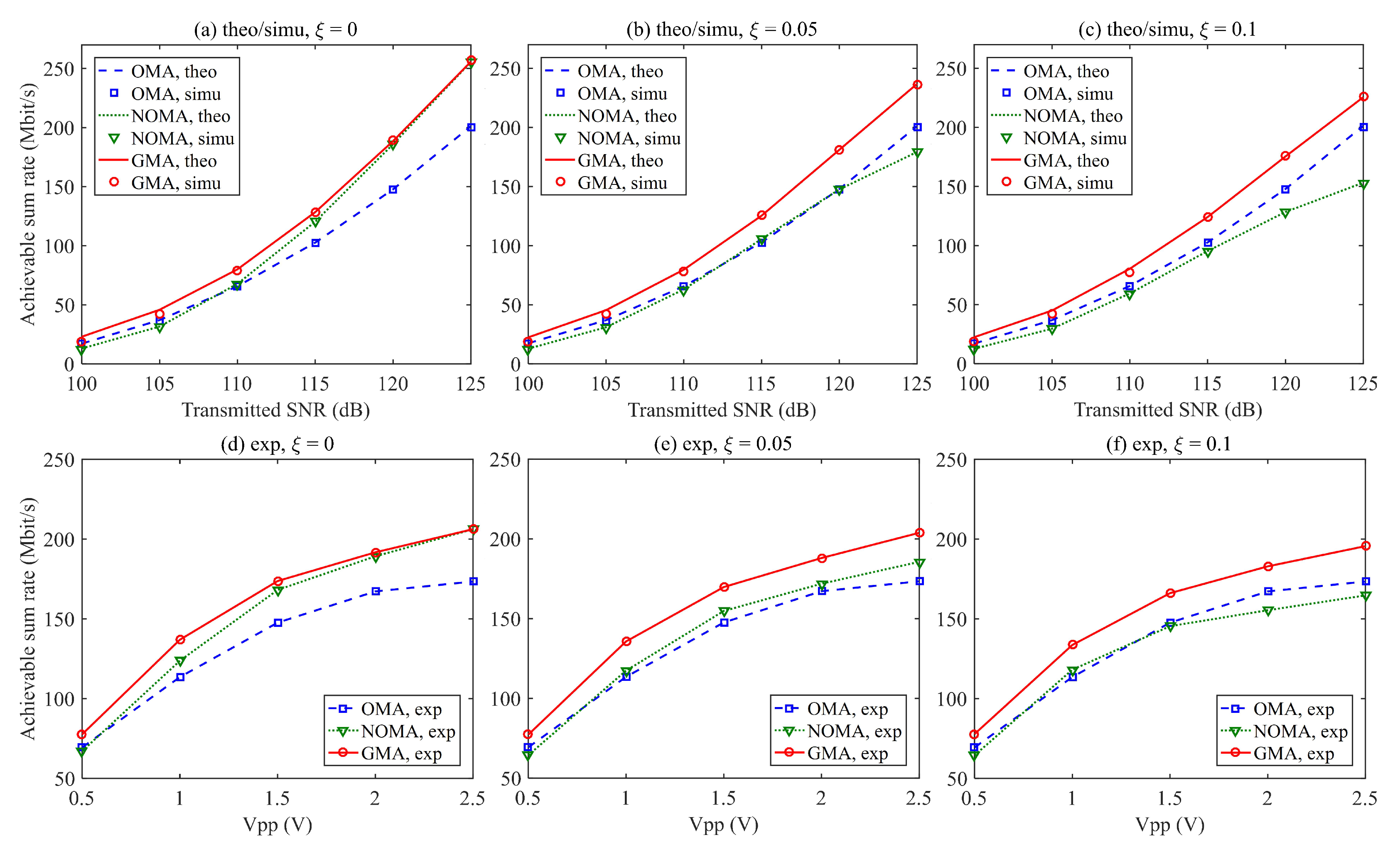
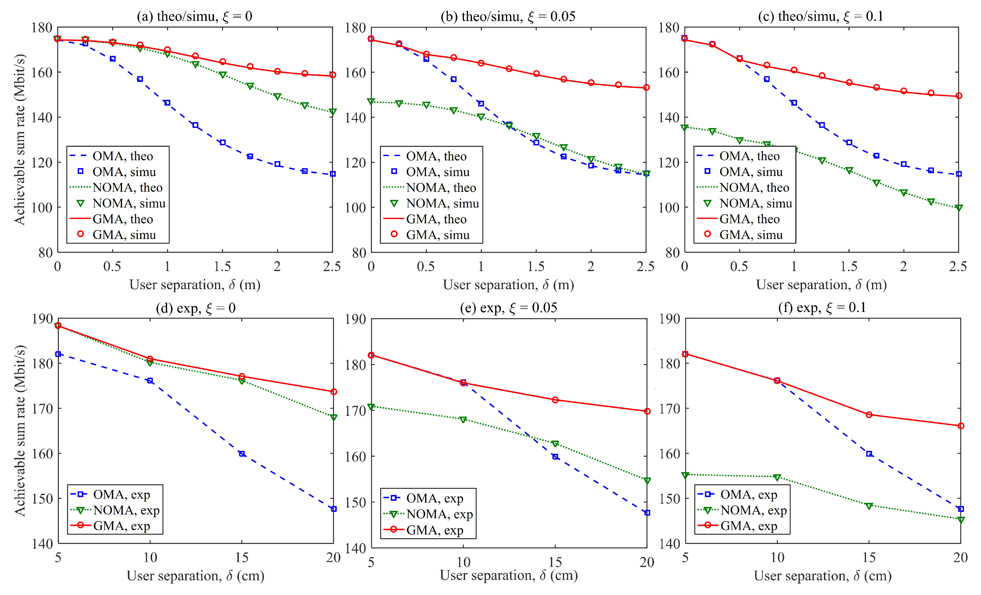
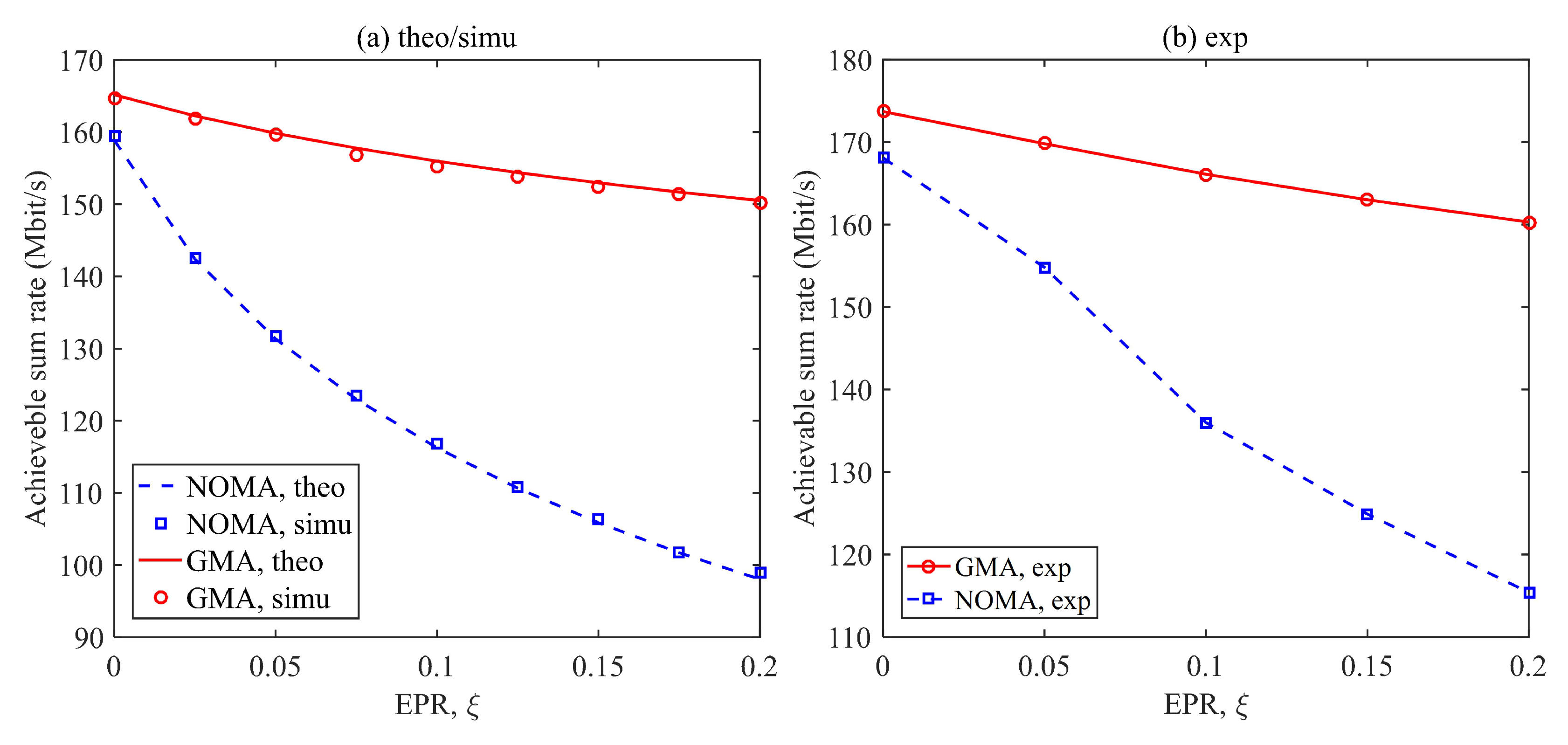
3.2. Performance Evaluation and Comparison
4. Conclusions
Author Contributions
Funding
Institutional Review Board Statement
Informed Consent Statement
Data Availability Statement
Acknowledgments
Conflicts of Interest
References
- Yang, P.; Xiao, Y.; Xiao, M.; Li, S. 6G wireless communications: Vision and potential techniques. IEEE Netw. 2019, 33, 70–75. [Google Scholar] [CrossRef]
- Cogalan, T.; Haas, H. Why would 5G need optical wireless communications? In Proceedings of the IEEE 28th Annual International Symposium on Personal, Indoor, and Mobile Radio Communications (PIMRC), Montreal, QC, Canada, 8–13 October 2017; pp. 1–6. [Google Scholar]
- Komine, T.; Nakagawa, M. Fundamental analysis for visible-light communication system using LED lights. IEEE Trans. Consum. Electron. 2004, 50, 100–107. [Google Scholar] [CrossRef]
- Chi, N.; Zhou, Y.; Wei, Y.; Hu, F. Visible light communication in 6G: Advances, challenges, and prospects. IEEE Veh. Technol. Mag. 2020, 15, 93–102. [Google Scholar] [CrossRef]
- Demirkol, I.; Camps-Mur, D.; Paradells, J.; Combalia, M.; Popoola, W.; Haas, H. Powering the Internet of Things through light communication. IEEE Commun. Mag. 2019, 57, 107–113. [Google Scholar] [CrossRef] [Green Version]
- Obeed, M.; Salhab, A.M.; Alouini, M.S.; Zummo, S.A. On optimizing VLC networks for downlink multi-user transmission: A survey. IEEE Commun. Surv. Tutor. 2019, 21, 2947–2976. [Google Scholar] [CrossRef] [Green Version]
- Eltokhey, M.W.; Khalighi, M.A.; Ghassemlooy, Z. Optimization of receivers’ field of views in multi-user VLC networks: A bio-inspired approach. IEEE Wirel. Commun. 2022, 29, 132–139. [Google Scholar] [CrossRef]
- Linnartz, J.P.M.; Deng, X.; Alexeev, A.; Mardanikorani, S. Wireless communication over an LED channel. IEEE Commun. Mag. 2020, 58, 77–82. [Google Scholar] [CrossRef]
- Abdelhady, A.M.; Amin, O.; Chaaban, A.; Shihada, B.; Alouini, M.S. Downlink resource allocation for dynamic TDMA-based VLC systems. IEEE Trans. Wirel. Commun. 2019, 18, 108–120. [Google Scholar] [CrossRef] [Green Version]
- Sung, J.Y.; Yeh, C.H.; Chow, C.W.; Lin, W.F.; Liu, Y. Orthogonal frequency-division multiplexing access (OFDMA) based wireless visible light communication (VLC) system. Opt. Commun. 2015, 355, 261–268. [Google Scholar] [CrossRef]
- Lian, J.; Brandt-Pearce, M. Multiuser visible light communication systems using OFDMA. J. Lightw. Technol. 2020, 38, 6015–6023. [Google Scholar] [CrossRef]
- Qiu, Y.; Chen, S.; Chen, H.H.; Meng, W. Visible light communications based on CDMA technology. IEEE Wirel. Commun. 2018, 25, 178–185. [Google Scholar] [CrossRef]
- Chen, D.; Fan, K.; Wang, J.; Lu, H.; Jin, J.; Feng, L.; Chen, H.; Xue, Z.; Wang, Y. Integrated visible light communication and positioning CDMA system employing modified ZCZ and Walsh code. Opt. Express 2022, 30, 40455–40469. [Google Scholar] [CrossRef]
- Marshoud, H.; Kapinas, V.M.; Karagiannidis, G.K.; Muhaidat, S. Non-orthogonal multiple access for visible light communications. IEEE Photonics Technol. Lett. 2016, 28, 51–54. [Google Scholar] [CrossRef] [Green Version]
- Marshoud, H.; Sofotasios, P.C.; Muhaidat, S.; Karagiannidis, G.K.; Sharif, B.S. On the performance of visible light communication systems with non-orthogonal multiple access. IEEE Trans. Wirel. Commun. 2017, 16, 6350–6364. [Google Scholar] [CrossRef] [Green Version]
- Chen, C.; Zhong, W.D.; Yang, H.; Du, P.; Yang, Y. Flexible-rate SIC-free NOMA for downlink VLC based on constellation partitioning coding. IEEE Wirel. Commun. Lett. 2019, 8, 568–571. [Google Scholar] [CrossRef]
- Wu, T.; Wang, Z.; Han, S.; Yu, J.; Jiang, Y. Demonstration of performance improvement in multi-user NOMA VLC system using joint transceiver optimization. Photonics 2022, 9, 168. [Google Scholar] [CrossRef]
- Lin, B.; Lai, Q.; Ghassemlooy, Z.; Tang, X. A machine learning based signal demodulator in NOMA-VLC. J. Light. Technol. 2021, 39, 3081–3087. [Google Scholar] [CrossRef]
- Chen, C.; Fu, S.; Jian, X.; Liu, M.; Deng, X.; Ding, Z. NOMA for energy-efficient LiFi-enabled bidirectional IoT communication. IEEE Trans. Commun. 2021, 69, 1693–1706. [Google Scholar] [CrossRef]
- Yin, L.; Popoola, W.O.; Wu, X.; Haas, H. Performance evaluation of non-orthogonal multiple access in visible light communication. IEEE Trans. Commun. 2016, 64, 5162–5175. [Google Scholar] [CrossRef] [Green Version]
- Lin, B.; Ye, W.; Tang, X.; Ghassemlooy, Z. Experimental demonstration of bidirectional NOMA-OFDMA visible light communications. Opt. Express 2017, 25, 4348–4355. [Google Scholar] [CrossRef]
- Chen, C.; Tang, Y.; Cai, Y.; Liu, M. Fairness-aware hybrid NOMA/OFDMA for band-limited multi-user VLC systems. Opt. Express 2021, 29, 42265–42275. [Google Scholar] [CrossRef]
- Chen, C.; Zhong, W.D.; Yang, H.; Du, P. On the performance of MIMO-NOMA-based visible light communication systems. IEEE Photonics Technol. Lett. 2018, 30, 307–310. [Google Scholar] [CrossRef]
- Chen, C.; Zhang, R.; Wen, W.; Liu, M.; Du, P.; Yang, Y.; Ruan, X. Hybrid 3DMA for multi-user MIMO-VLC. J. Opt. Commun. Netw. 2022, 14, 780–791. [Google Scholar] [CrossRef]
- Naser, S.; Sofotasios, P.C.; Bariah, L.; Jaafar, W.; Muhaidat, S.; Al-Qutayri, M.; Dobre, O.A. Rate-splitting multiple access: Unifying NOMA and SDMA in MISO VLC channels. IEEE Open J. Veh. Technol. 2020, 1, 393–413. [Google Scholar] [CrossRef]
- Tao, S.; Yu, H.; Li, Q.; Tang, Y.; Zhang, D. One-layer rate-splitting multiple access with benefits over power-domain NOMA in indoor multi-cell visible light communication networks. In Proceedings of the IIEEE International Conference on Communications Workshops (ICC Workshops), Dublin, Ireland, 7–11 June 2020; pp. 1–7. [Google Scholar]
- Xing, F.; He, S.; Leung, V.C.; Yin, H. Energy efficiency optimization for rate-splitting multiple access-based indoor visible light communication networks. IEEE J. Sel. Areas Commun. 2022, 40, 1706–1720. [Google Scholar] [CrossRef]
- Kim, B.; Park, Y.; Hong, D. Partial non-orthogonal multiple access (P-NOMA). IEEE Wirel. Commun. Lett. 2019, 8, 1377–1380. [Google Scholar] [CrossRef]
- Deng, X.; Fan, W.; Cunha, T.E.B.; Ma, S.; Chen, C.; Dong, Y.; Zou, X.; Yan, L.; Linnartz, J.P.M.G. Two-dimensional power allocation for optical MIMO-OFDM systems over low-pass channels. IEEE Trans. Veh. Technol. 2022, 71, 7244–7257. [Google Scholar] [CrossRef]
- Zeng, L.; O’Brien, D.C.; Le Minh, H.; Faulkner, G.E.; Lee, K.; Jung, D.; Oh, Y.; Won, E.T. High data rate multiple input multiple output (MIMO) optical wireless communications using white LED lighting. IEEE J. Sel. Areas Commun. 2009, 27, 1654–1662. [Google Scholar] [CrossRef]
- Kahn, J.M.; Barry, J.R. Wireless infrared communications. Proc. IEEE 1997, 85, 265–298. [Google Scholar] [CrossRef] [Green Version]
- Haas, H.; Yin, L.; Wang, Y.; Chen, C. What is LiFi? J. Lightw. Technol. 2016, 34, 1533–1544. [Google Scholar] [CrossRef]
- Chen, C.; Zhong, X.; Fu, S.; Jian, X.; Liu, M.; Yang, H.; Alphones, A.; Fu, H.Y. OFDM-based generalized optical MIMO. J. Light. Technol. 2021, 39, 6063–6075. [Google Scholar] [CrossRef]


| Variable | Definition |
|---|---|
| A | Active area of the PD |
| B | Signal bandwidth |
| Distance between the LED and the PD of the k-th user | |
| DC channel gain between the LED and the k-th user | |
| Amplitude attenuation coefficient at the i-th subcarrier of the k-th user | |
| Gain of the optical lens | |
| m | Order of Lambertian emission |
| PSD of the AWGN | |
| Additive noise at the i-th subcarrier of the k-th user | |
| r | Refractive index of the optical lens |
| Set of subcarriers allocated to the k-th user | |
| Gain of the optical filter | |
| Transmitted electrical signal at the i-th subcarrier | |
| Received electrical signal at the i-th subcarrier of the k-th user | |
| Emission angle from the LED to the k-th user | |
| Incident angle from the LED to the k-th user | |
| Semi-angle at half power of the LED | |
| Half-angle field-of-view (FOV) of the optical lens | |
| PD responsivity |
| Acronym | Definition |
|---|---|
| AWGN | Additive white Gaussian noise |
| CDMA | Code division multiple access |
| FOV | Field-of-view |
| GMA | Generalized multiple access |
| IoT | Internet of Things |
| IUI | Inter-user interference |
| LED | Light-emitting diode |
| LOS | Line-of-sight |
| MIMO | Multiple-input, multiple-output |
| MISO | Multiple-input, single-output |
| NLOS | Non-line-of-sight |
| NOMA | Non-orthogonal multiple access |
| OFDM | Orthogonal frequency division multiplexing |
| OFDMA | Orthogonal frequency division multiple access |
| OMA | Orthogonal multiple access |
| PSD | Power spectral density |
| RF | Radio frequency |
| RSMA | Rate-splitting multiple access |
| SDMA | Space-division multiple access |
| SIC | Successive interference cancellation |
| SPC | Superposition coding |
| TDMA | Time division multiple access |
| VLC | Visible light communication |
| Parameter | Value |
|---|---|
| Vertical separation | 2.15 m |
| Semi-angle at half power of LED | |
| Gain of optical filter | 0.9 |
| Refractive index of optical lens | 1.5 |
| Half-angle FOV of optical lens | |
| Responsivity of PD | 0.53 |
| Active area of PD | 1 |
| Signal bandwidth | 39.1 MHz |
| Noise power spectral density |
Disclaimer/Publisher’s Note: The statements, opinions and data contained in all publications are solely those of the individual author(s) and contributor(s) and not of MDPI and/or the editor(s). MDPI and/or the editor(s) disclaim responsibility for any injury to people or property resulting from any ideas, methods, instructions or products referred to in the content. |
© 2023 by the authors. Licensee MDPI, Basel, Switzerland. This article is an open access article distributed under the terms and conditions of the Creative Commons Attribution (CC BY) license (https://creativecommons.org/licenses/by/4.0/).
Share and Cite
Tang, Y.; Chen, C.; Liu, M.; Du, P.; Fu, H.Y. Rate-Splitting-Based Generalized Multiple Access for Band-Limited Multi-User VLC. Photonics 2023, 10, 446. https://doi.org/10.3390/photonics10040446
Tang Y, Chen C, Liu M, Du P, Fu HY. Rate-Splitting-Based Generalized Multiple Access for Band-Limited Multi-User VLC. Photonics. 2023; 10(4):446. https://doi.org/10.3390/photonics10040446
Chicago/Turabian StyleTang, Yuru, Chen Chen, Min Liu, Pengfei Du, and H. Y. Fu. 2023. "Rate-Splitting-Based Generalized Multiple Access for Band-Limited Multi-User VLC" Photonics 10, no. 4: 446. https://doi.org/10.3390/photonics10040446