1. Introduction
Ultrashort-pulse mode-locked fiber lasers have attracted extensive attention owing to their potential applications in the fields of high-precision micro-machining, nonlinear optics and biological imaging, etc. [
1,
2,
3,
4,
5]. The robustness and reliability of ultrafast fiber lasers is affected by the mode locking technique. Generally, two main categories of mode locking methods are widely employed to realize the generation of ultrashort pulses in fiber lasers. One type refers to the real saturable absorbers (SAs), such as semiconductor saturable absorber mirrors (SESAM) [
6], novel two-dimensional materials [
7,
8,
9] and oxide saturable absorbers [
10]. The other category refers to artificial saturable absorbers including nonlinear polarization rotation (NPR) [
11,
12,
13,
14] and nonlinear amplifying loop mirrors (NALM) [
15,
16,
17,
18,
19]. However, real SAs may suffer from a low damage threshold and potential degradation over time [
20]. Normally, the cavity of an NPR mode-locked fiber laser cannot be constructed using polarization-maintaining (PM) fiber, which limits its application in unstable conditions. Although many efforts have been made to realize NPR with an all-fiber and all-PM structure [
21,
22], it requires splicing the PM fiber at the proper angle or using other optimization methods, which inevitably adds complexity and extra losses in the cavity.
Compared with real SAs and conventional NPR methods, fiber lasers mode-locked by the NALM technique are more robust due to their all-PM configuration and the abandonment of real SAs. The mode locking mechanism of NALM relies on the interference between two counter-propagating pulses inside a fiber loop connected by a beam splitter. One drawback of NALM mode-locked fiber lasers, e.g., figure-8 fiber lasers [
23], is the difficulty in self-starting, due to the weak intensity dependence caused by the phase difference between the clockwise (
cw) and counterclockwise (
ccw) propagating pulses. Therefore, more robust mode locking techniques with better self-start performance are desirable. Recently, figure-9 fiber lasers based on phase-biased NALM configuration have attracted great interest due to the artful modification of the laser cavity so that the mode locking is self-started easily [
16]. Specifically, an additional linear phase bias is introduced in the ring mirror or linear arm of the figure-9 cavity. Thanks to the extra phase bias, the transmission level of the running continuous wave (CW) as well as the noise pulse increases at the laser starting point. Therefore, the mode locking threshold is reduced and the self-starting becomes easier compared to NALM fiber lasers without linear phase bias [
16,
23]. Commonly, the phase biasing module consists of a set of wave plates and Faraday rotators [
24,
25]. If the phase shifter is composed of several adjustable space optical wave plates, both the phase bias and modulation depth can be adjusted by rotating the wave plate angle, so that the tunable structure can have more freedom in the emitting pulses’ optimization. It has been shown that the figure-9 fiber lasers based on the NALM configuration not only generate optical pulses with a narrow pulse width, high repetition rate and ultra-low noise and time jitter level [
26,
27,
28], but also have very high robustness to meet the application conditions in extreme environments [
29]. Although there have been many previous studies on the properties of figure-9 fiber lasers reported so far, their wavelength tuning properties are rarely reported. The influence of the cavity parameters (e.g., phase shift and pump power) on the wavelength tuning outcomes has not been observed, and the mechanism of wavelength tuning remains to be explored.
In this work, we demonstrate an all-PM Er-doped soliton mode-locked fiber oscillator based on the figure-9 configuration. A compact reflection-type non-reciprocal phase shifter is implemented for reducing the mode-locking threshold of the laser. An analytical model based on the Jones matrix is established to qualitatively simulate the wavelength tuning phenomenon. It is observed that the increase in pump power results in a significant redshift in the spectrum of output pulses. As the angle of the half-wave plate is rotated in one direction, the output spectrum is redshifted and then blueshifted successively. The simulated results are well validated by the experiments. It is shown that the adjustment of pump power causes the change in the nonlinear phase shift difference of the NALM. The angle rotation of wave plates not only changes the nonlinear phase shift difference, but also causes a difference in laser phase bias and modulation depth. The change in these parameters leads to a difference in the distribution of the laser output transmission curves, which results in wavelength tuning. This work provides a new perspective for the design of continuously tunable mode-locked figure-9 fiber lasers and the expansion of their applications.
2. Experimental Setup and Theoretical Analysis
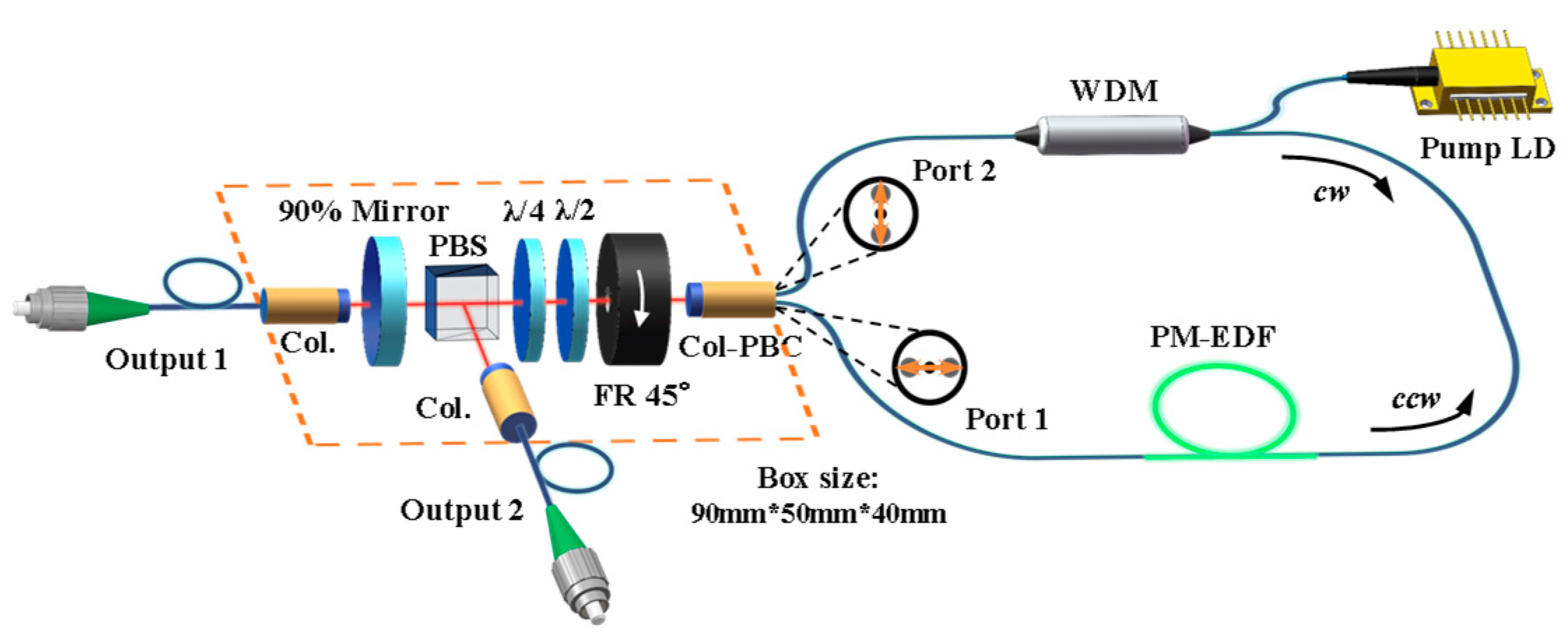
A schematic illustration of the figure-9 fiber oscillator is shown in
Figure 1. The cavity consists of two modules, the NALM segment and a linear arm. The NALM is composed of a polarization beam combiner integrated with a collimation lens (Col-PBC), a PM wavelength division multiplexer (WDM), 0.6 m of PM erbium-doped fiber (PM-EDF, Er80-8/125-PM) with anomalous dispersion of −0.023 ps
2/m and 3.25 m of PM single-mode fiber (PM1550) with dispersion of −0.023 ps
2/m. The PM-EDF, with ~80 dB/m absorption at 1530 nm, is used as the gain medium. In order to increase the nonlinear phase shift difference between the two counter-propagating pulses, the PM-EDF is placed asymmetrically in the fiber loop and pumped by a 976 nm laser diode (LD) through the WDM, which facilitates the self-starting of mode locking. In particular, there are 0.7 m and 2.55 m of the PM1550 on the front and back sides of the PM-EDF along the
ccw direction, respectively. By passing through the PBS at the end of the NALM fiber loop, the polarization of pulses from the
cw and
ccw directions is twisted by a 90° angle. Then, they are combined and coupled into the linear arm though the Col-PBC. The two combined beams with orthogonal polarizations from the collimator pass through a non-reciprocal phase shifter consisting of a 45° Faraday rotator (FR), a half-wave plate (HWP) and a quarter-wave plate (QWP). The linear phase shift can be adjusted by rotating these two wave plates. A polarization beam splitter (PBS) is placed behind the phase shifter. Then, coherent polarization interference between the two combined beams occurs at the PBS, resulting in intensity-dependent transmission characteristics at both ports. The peak part of the pulse is more powerful; thus, it is easier to achieve a large phase difference and thus has higher transmittance. The two wings of the pulse are reflected due to the weak light intensity and insufficient phase shift. This process forms the pulse narrowing mechanism, or an artificial “saturable absorber”. The
p-polarized light, transmitted from the PBS, is 90% reflected back and 10% coupled to the output port 1 via a 90% reflected end-mirror on the linear arm. The rejected part of the light (
s-polarized) is coupled out to output 2 from the PBS. The linear arm is integrated in a compact box with a size of 90 × 50 × 40 mm
3. The physical length of the linear arm is only ~7.5 cm. The total optical path length of the laser is 5.77 m, and the corresponding pulse repetition rate is 52 MHz. The net cavity dispersion is estimated to be approximately −0.09 ps
2.
According to the cavity setup shown in
Figure 1, we deduce the cavity roundtrip transmission function. It is assumed that the light passes through the PBS, QWP, HWP, FR, Col-PBC, and NALM. Then, the light returns by the same route to the PBS. In particular, the intracavity elements are expressed by their corresponding Jones matrices [
30]. Thus, the intracavity electric field,
, after one roundtrip is obtained:
where
= (1,0) is the normalized field vector along the
x-axis, i.e., corresponding to the
p-polarized light transmitted from the PBS. The other terms in Equation (1) are the Jones matrices of the corresponding components in the resonator, where
is the Jones matrix of the transmittance of PBS.
is the Jones matrix of light transmission through the fiber loop of NALM.
represents the nonlinear phase shift difference accumulated after the light passes through the fiber loop.
and
are the fast-axis angles of HWP and QWP, respectively.
is the nonlinear phase difference between the
ccw and
cw light. Then, the cavity roundtrip transmission function
T corresponds to
which can be simplified as
where
can be obtained by calculating the following formula [
31]:
where
and
are the nonlinear phase shifts accumulated in the NALM by the
cw and
ccw transmitting optical fields.
g1 and
g2 are the gains of
ccw and
cw propagating light in NALM, respectively.
P0 is the peak power of the pulse incident into the NALM.
n2 is the nonlinear refractive index of the fiber.
L2 is the length of EDF (0.6 m), and
α is the energy splitting ratio coupled into port 1 at the loop entrance. Obviously, the value of
can be either positive or negative, and its absolute value is jointly determined by the peak power
P0, the splitting ratio
α and the asymmetry of NALM. The splitting ratio
α is defined as
The normalized field vector at the entrance of the loop can be expressed as
From Equation (3) above, it is deduced that different combinations of
and
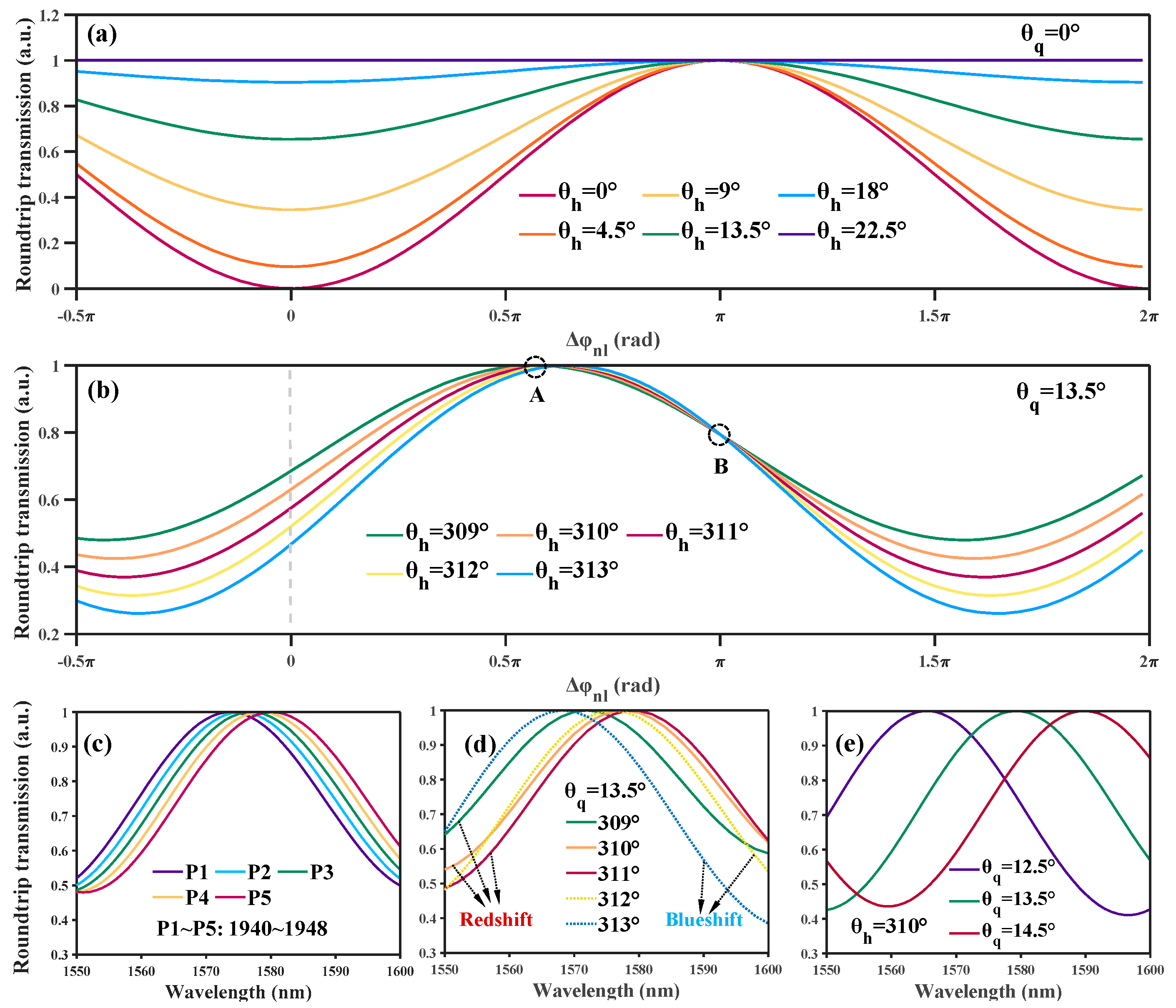
result in different roundtrip transmissions in the cavity. The simulation results of the cavity roundtrip transmission function
T are presented in
Figure 2. As shown in
Figure 2a, when
is 0° (that is, the fast axis of the QWP is parallel to the x-axis), adjusting
only changes the modulation depth, and not the linear phase bias. It is difficult to achieve self-starting operation in these states because small deviations of
from zero only lead to small changes in the cavity losses. There is another special case of
= 45°, where the incident, linearly polarized light is converted to circularly polarized light after passing through QWP. At this time, the light coupled to Col-PBC remains circularly polarized as the HWP is rotated. The optical splitting ratio α of NALM continues to be 0.5. In this case, the maximum transmission is obtained at the point of
= 0. This indicates that the laser exhibits decreasing transmission as a function of
and the laser works in the region of negative saturation absorption, resulting in difficult self-starting operation. When
is not 0° and is not an integer multiple of 45°, adjusting
changes both the modulation depth and the linear phase bias. As shown in
Figure 2b, when
is set to 13.5°, the transmission curves have different modulation depths and linear phase biases when tuning
. In this case, due to the introduced phase bias, the transmittance curves have a steeper slope around
= 0 than that of the cases in
Figure 2a, which means that the transmittance increases more quickly when increasing the pump power. Moreover, the linear phase bias results in partial CW transmission in the initial phase of pulse formation (corresponding to
= 0), which helps to generate the initial noise-like giant pulses required for mode locking and to enhance the self-starting ability of the mode locking. Theoretically, it can be defined that the value range, where the pulse transmittance is greater than the CW component, is the region of single-pulse mode locking operation [
32].
According to Equations (3) and (6), the transmittance curves as a function of wavelength are qualitatively simulated. For the case of
= 13.5° and
= 310°, as the pump power increases from
P1 to
P5, the spectrum of the output pulses is redshifted, as shown in
Figure 2c. Furthermore, the wavelength tuning induced by rotating
is simulated, as shown in
Figure 2d. Interestingly, the phenomenon of non-unidirectional spectral tuning is observed with the unidirectional change of
. By increasing the angle of
, the transmission curve with the wavelength of port 1 is first redshifted and then blueshifted successively. This is because different
leads to different transmittance curve distributions. Similarly, the simulation of the transmission spectrum change caused by rotation
is shown in
Figure 2e. We note that the increase in
leads to a spectral redshift. A small change in
leads to a relatively larger step of wavelength tuning compared to adjusting
. Therefore, it is numerically shown that the wavelength tuning in our proposed laser cavity is strongly correlated to the pulse peak power (namely, the nonlinear phase shift) and the angle combinations of wave plates.
3. Experiment Results and Discussion
Once the angles of QWP and HWP are adjusted to the appropriate position, the self-started mode locking operation can be achieved by increasing the pump power of LD to the level of 250 mW. Compared with the traditional figure-8 mode-locked oscillator without a phase shifter [
33], the mode-locked threshold is significantly reduced, and no additional mechanical disturbance is required to trigger the self-starting of mode locking. Experimentally, there is a series of angle combinations of wave plates in the whole parameter space of the figure-9 cavity laser to achieve mode-locked pulses. Inspired by the simulation results shown in
Figure 2, the angles of QWP and HWP are set to be
= 15° and
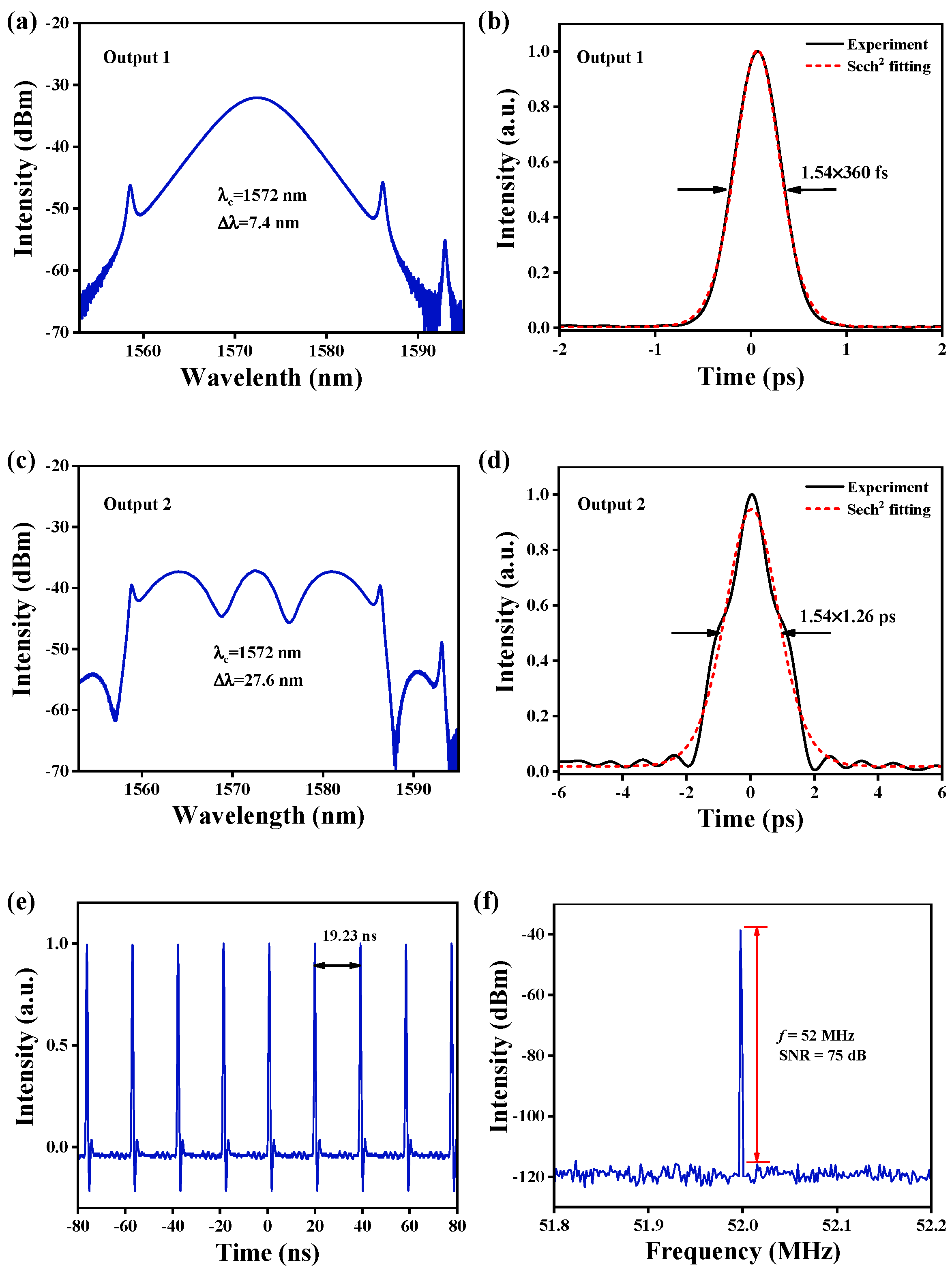
= 328°, respectively. We note that there are minor differences in the angles of the wave plates between the experiment and the simulation, which is due to the angle errors in the installation of the PBS, the wave plates and the polarizer integrated in Col-PBC. Initially, the laser operates in a multi-pulse soliton mode locking state. By decreasing the pump power below 78 mw, the single-pulse operation is obtained. The minimum pump power level to maintain the laser mode locking is 63 mW. The mode locking performance at the pump power of 65 mW is shown in
Figure 3. The spectral characteristics of both output ports are recorded via an optical spectrum analyzer with a wavelength resolution of 0.02 nm, as presented in
Figure 3a,c. The full widths at half maximum (FWHM) of the optical spectra are 7.4 nm and 27.6 nm for output 1 and output 2, respectively. The output pulses are conventional soliton pulses because of the typical characteristic Kelly sidebands on both sides of the spectra.
Figure 3b,d show the autocorrelation traces of output 1 and output 2 measured by an optical autocorrelator (measurable wavelength range: 1000~1600 nm). When assuming a Sech
2 pulse profile, the corresponding pulse durations are ~360 fs and ~1.26 ps, respectively. The repetition rate of the pulse train is 52 MHz, recorded by a digital oscilloscope with 1 GHz bandwidth, corresponding to a pulse interval of approximately 19.2 ns, as indicated in
Figure 3e. Moreover,
Figure 3f shows the radio frequency (RF) spectrum of the first harmonic of the transmission port measured by an RF spectrum analyzer. The corresponding signal-to-noise ratio (SNR) is as high as 75 dB with a resolution bandwidth (RBW) of 200 Hz, which indicates the low-amplitude fluctuation and stable operating state of the mode locking.
It is worth noting that the output characteristics of the transmission port (output 1) and rejection port (output 2) are clearly different in both spectral and temporal domains. The pulses emitting from the transmission port have a soliton-type spectrum and a near-perfect Sech
2 pulse shape, as shown in
Figure 3a,b. In contrast, the optical spectra of the pulses at the rejection port are noticeably modulated. This is because the backpropagated pulses experience different nonlinear phase shifts due to the gain asymmetry of the NALM segment, so that their temporal and spectral shapes contrast each other when interference occurs [
34,
35]. Since there is a reflecting end mirror at the transmission port, as the pulse evolves in the cavity, the phase shift accumulated by the pulse transmission in NALM is selected to positively affect the increase in the peak power of the pulse at the transmission port due to the saturable absorption effect. Meanwhile, the rejection port consists of radiation affected by destructive interference, resulting in spectrum sag and poor pulse quality. In the following experiments, we focus on the case of transport ports.
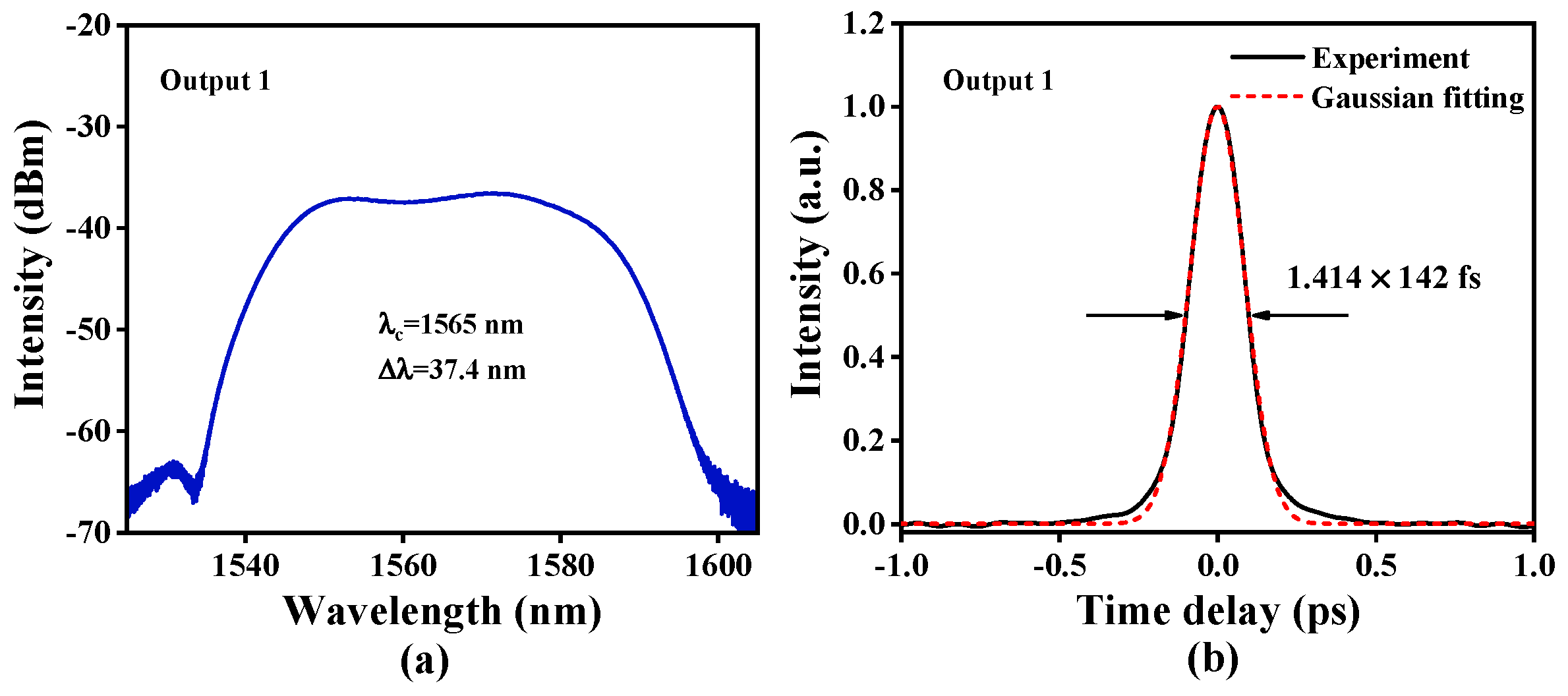
By adding a 1.0-m-length dispersion-compensating fiber (DCF, PM2000D) into the cavity and adjusting the length of the PM1550 fiber appropriately for further dispersion management, the laser is in the state of stretch pulse mode-locked when the net dispersion of the cavity is near-zero micro-negative. In this case, the center wavelength of the spectrum of output 1 is at 1565 nm with an FWHM of 37.4 nm, as shown in
Figure 4a. The output pulses with slightly negative chirp are compressed by a piece of PM2000D fiber. The autocorrelation trace of the de-chirped pulses with a pulse duration of 142 fs is shown in
Figure 4b, which has a near-perfect Gaussian-function shape. The time bandwidth product (TBP) is 0.65. According to the FWHM of the spectrum, the Fourier transform limited pulse duration is 96 fs. This indicates that there are still some high-order dispersions in the laser cavity that are difficult to compress by DCF. It is worth mentioning that when the laser is operating in the stretch pulse mode-locked state, the spectrum is greatly broadened due to the high peak power of the pulses in the cavity. Due to the relatively larger nonlinear phase shift compared with soliton pulses, the stretched pulses are more easily destroyed during the rotation of the wave plates. Therefore, we prefer the conventional soliton mode locking region to verify the above simulation results in the experiments, where the wavelength tuning characteristics are more obvious.
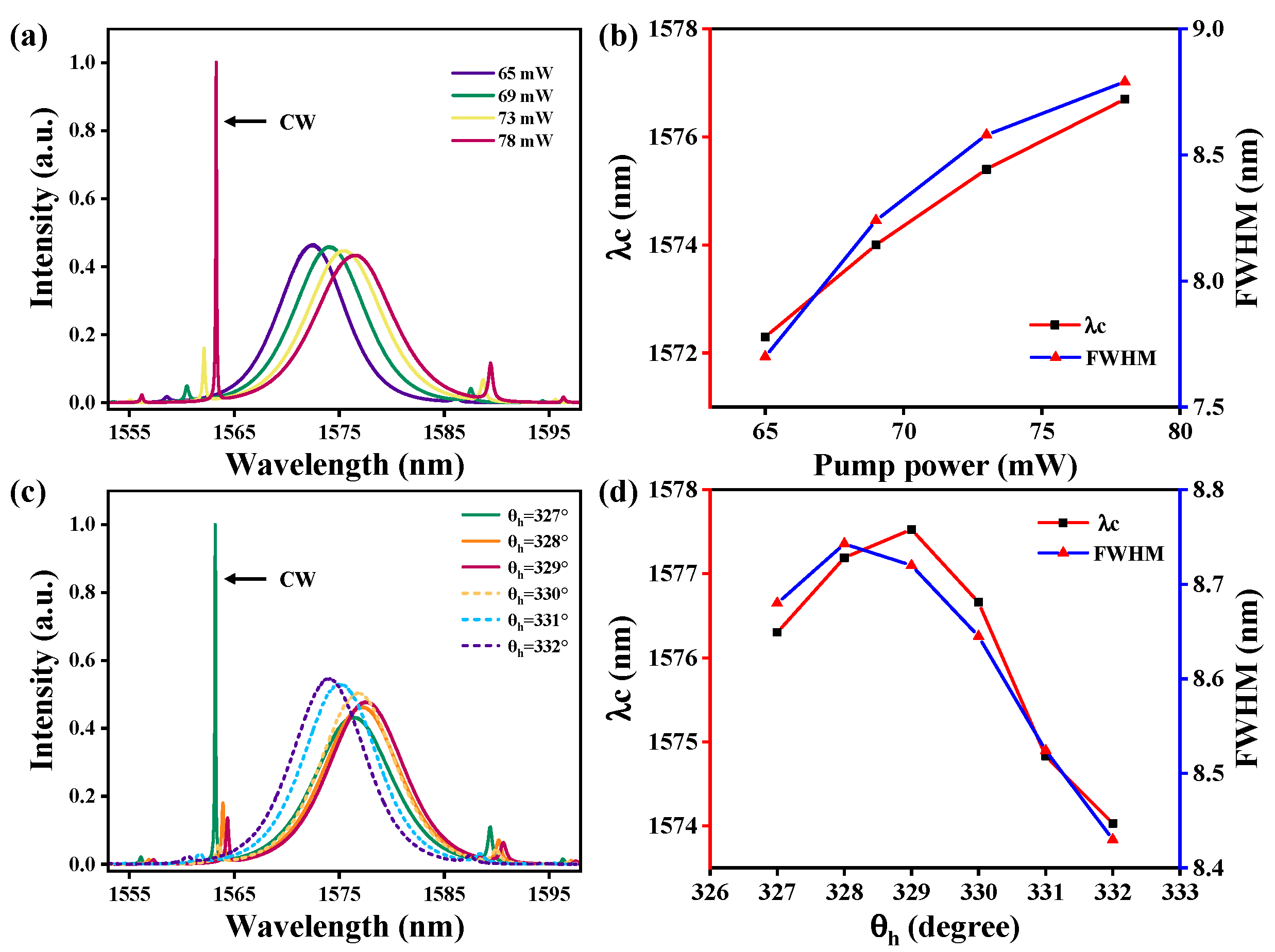
When the pump power is gradually increased from 65 mW to 78 mW, it is observed that the spectrum of the output pulses is redshifted, as shown in
Figure 5a. The central wavelength of the output spectrum is tunable from 1572 nm to 1577 nm. The reason for the pump-induced wavelength tuning is that the increase in pump intensity leads to an increase in the nonlinear phase shift difference, which causes the transmittance curves about the wavelength to move to the long-wave direction. The experimental results are in good agreement with the above simulation results shown in
Figure 2c.
Figure 5b presents the central wavelength and FWHM of the main spectral peak as a function of pump power. We note that the FWHM increases monotonically with the rising pump power, due to the self-phase modulation effect [
26]. It should be emphasized that when the pump power is increased to 78 mW, an obvious CW component appears on the spectrum, overlapping with the left-side first-order Kelly sideband. Continuing to increase the pump results in more CW components of the spectrum and a smaller redshift step in the spectrum. This can be explained as follows. As the
of NALM increases, the laser operating point gradually shifts from point A, with large transmittance, to point B, with small pulse transmittance, as shown in
Figure 2b. Therefore, more of the light wave is output in the form of the CW component.
The wavelength tuning triggered by rotating the HWP is shown in
Figure 5c for the case in which the pump power is kept at 75 mW. In the tuning range of 327° to 332°, gradually increasing
results in continuous wavelength tuning. The spectrum is first redshifted and then blueshifted, and the tuning range of the central wavelength is 1574 nm to 1577.5 nm. The experimental wavelength tuning phenomenon agrees well with the simulation results in
Figure 2d above. The reason for this wavelength tuning phenomenon is that the change in
leads to the different transmittance curve distribution of the output pulses.
Figure 5d presents the variation in the FWHM and central wavelength of the main spectral peak of the pulse when
is adjusted. It is thus evident that the FWHM has the same variation trend as the central wavelength. This demonstrates that adjusting
not only causes the wavelength shift of the laser output transmission curve, but also leads to the spectral bandwidth change. The longer spectral wavelength corresponds to a larger FWHM. It should be pointed out that when
decreases to 327°, the CW component begins to appear in the spectrum, as shown in
Figure 5c. The reason is as follows.
The laser works in the negative saturation absorption region when the pump power is greater than 65 mW, as shown in
Figure 5a. When the pump power is kept at 75 mW, the main spectral peak of the intracavity pulse decreases when reducing the
. This indicates that the output transmission of the laser pulse light becomes smaller, i.e., the nonlinear phase shift difference increases. Moreover, the transmittance of the CW is located at the point of
= 0. According to the simulation results in
Figure 2b, the smaller the
is, the larger transmittance the CW has. Therefore, the CW component appears on the spectrum of the output pulse when
decreases.
Experimentally, the laser fails to maintain the mode locking state when is less than 325°. This could be attributed to the fact that the nonlinear phase shift difference of the NALM exceeds the range that allows stable single-pulse mode locking. Moreover, the laser also cannot maintain mode-locked operation when is greater than 332°. The reason is clarified as follows. The main spectral peak increases with an increasing , which indicates that the output transmittance of the laser increases—that is, the nonlinear phase shift difference decreases. The transmittance of pulse light reaches its maximum value when = 332°. The continuing increase in leads to a smaller nonlinear phase shift difference and causes the laser to work in a negative saturated absorption state, which makes it difficult for the laser to maintain stable mode locking.
In addition, the Kelly sideband strength is also related to the rotation of HWP. As shown in
Figure 5c, the Kelly sidebands of the output spectrum are gradually suppressed when
is tuned from 327° to 332°. This phenomenon is similar to the situation of the pump power decreasing process, as shown in
Figure 5a. This indicates that the Kelly sideband strength depends not only on the pump strength but also on the nonlinear phase shift difference. The reduction of the nonlinear phase shift difference helps to suppress the Kelly sideband strength. Different from the situation in
Figure 5a, increasing
causes the laser to operate with larger pulse transmittance at higher pump power, which leads to a significant increase in the spectral energy of the output pulse, as shown in
Figure 5c. It is worth pointing out that based on this property, it is possible to increase the pulse energy while greatly suppressing the Kelly sideband strength by rotating HWP.
For the case of adjusting
, as expected from the simulation results in
Figure 2e, an increase in
does lead to a redshift in the wavelength. However, the mode-locked state of the laser is very sensitive to the change in
. The slight rotation of the QWP causes the laser to fail to maintain mode locking operation. This is due to the uneven shape of the Er
3+ ions’ emission spectrum [
36]. When adjusting
, it results in a large step shift in the spectrum, and the energy balance of the mode-locked state is easily destroyed due to drastic changes in the gain or loss of the pulses in the cavity.
The total wavelength tuning range for our experiments is 3.5~5 nm. We believe that by further nonlinear optimization and more detailed adjustment of the combination of wave plate angles, tunable pulses output in a wider spectral range can be obtained. Additionally, the figure-9 fiber laser introduced in this work is capable of continuous wavelength tuning without the aid of additional tunable optical bandpass filters [
37] or other wavelength tuning components, compared to traditional fiber lasers based on real SAs. It has important application value in optical fiber communication, optical fiber sensing, biological imaging and other fields.

 ,
, 


