
A Strain-Gauge-Based Method for the Compensation of Out-of-Plane Motions in 2D Digital Image Correlation

Abstract
:1. Introduction
2. Materials and Methods
2.1. Development of the Strain-Gauge-Based Error Compensation Method
2.1.1. Theoretical Error from Out-of-Plane Motion in 2D-DIC
2.1.2. Simplified Equation for the Total Error from Out-of-Plane Motion
- Translation perpendicular to the measurement plane (from Equation (2)):
- Rotation about the horizontal (in-plane) measurement axis (from Equation (4)):
- Rotation about the vertical (in-plane) measurement axis (from the result of performing the same derivation as for Equation (4), but around the vertical axis instead):where , and are the i-th points of , and , i.e., at time . The strain error equations have been given as functions of their instantaneous out-of-plane motion values, as the out-of-plane motions would likely be varying with time, i.e., throughout the measurement. Rotation about the z-axis was not considered here as the 2D-DIC algorithm is made to measure both in-plane translations and rotations, and as long as the in-plane rotation is relatively small, then it should not present any problems to the measurement ability of 2D-DIC [5,10].
2.1.3. Compensation of Error from Out-of-Plane Motion
2.2. Experimental Application of Strain Gauge Error Compensation Method
2.2.1. Test Setup
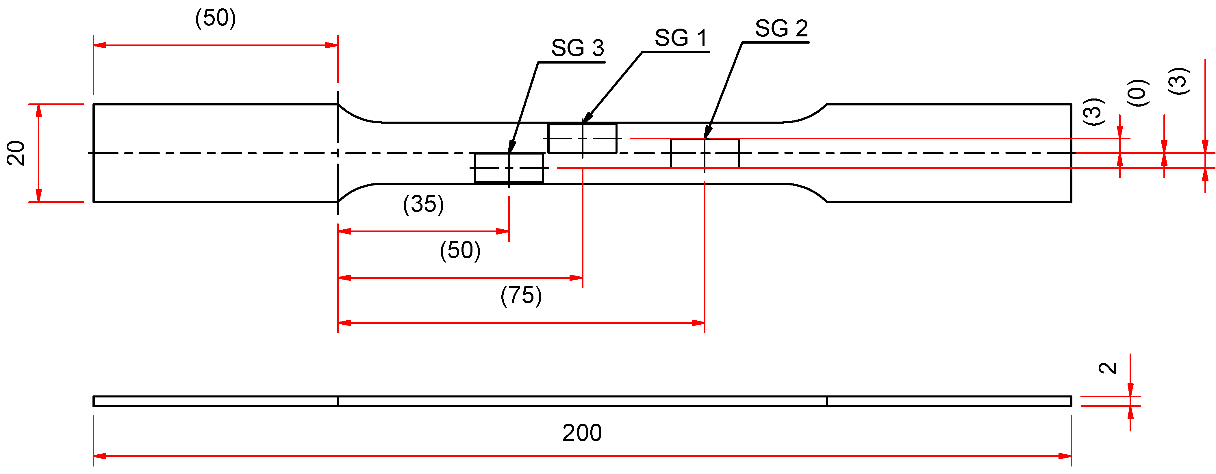
2.2.2. Test Specimens
2.2.3. Experimental Procedure
- Simple specimen tests: The specimen was only loaded to approximately half of the specimen material’s yield strength. This allows multiple tensile tests to be conducted on the same specimen within the elastic range of the specimen. In this manner, other experimental variables (for example, different speckle patterns and setup conditions) can be eliminated.
- Complex specimen tests: The specimens were loaded to past the ultimate strength of the specimen (where parts of the specimen had begun necking). The complex specimens were at first also loaded to only half of their material’s yield strength, so that the same specimen could be tested more than once, as in the simple specimen tests. To avoid exceeding half the yield strength anywhere in the specimen, the specimens were loaded to a force which resulted in a stress of half the yield strength at the stress concentrations. At this force, the rest of the specimen experienced very low strains, which were close to the 2D-DIC noise floor of the experiment. This made the DIC strain data very noisy and caused inaccuracies in the strain errors calculated between the 2D-DIC and strain gauge data. This meant that a fit of the strain errors (as in Equation (13)) would not accurately describe the strain error in the full-field 2D-DIC data, and so the error compensation method could not successfully be applied. A different specimen was, therefore, used in each of the tests and was loaded to above its yield strength so that high strains were induced across the whole strain field.
3. Results
3.1. Simple Tensile Specimen Tests
3.2. Complex Tensile Specimen Tests
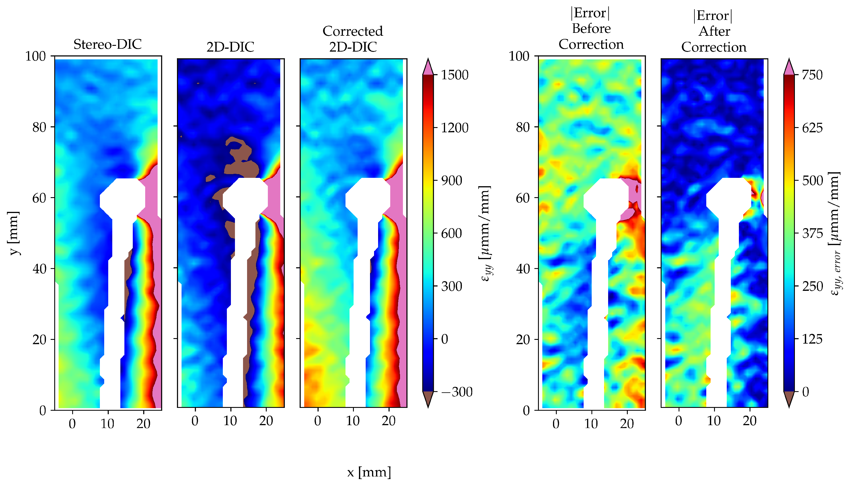
- Test 1: A significant improvement was obtained in the accuracy of the 2D-DIC measurement in Test 1, as is evident in Figure 9. Specifically, the contour plot of the corrected 2D-DIC data approaches the contour plot of the stereo-DIC data when compared to the original (uncorrected) 2D-DIC data contour plot. A clear reduction in the magnitude of the strain error values is also present over most of the strain field in the plots of the absolute strain error before and after correction.Figure 9. Contour plots of the stereo-DIC, 2D-DIC, corrected 2D-DIC and error data for strain in the y-direction for the 700th image of Test 1.Figure 9. Contour plots of the stereo-DIC, 2D-DIC, corrected 2D-DIC and error data for strain in the y-direction for the 700th image of Test 1.
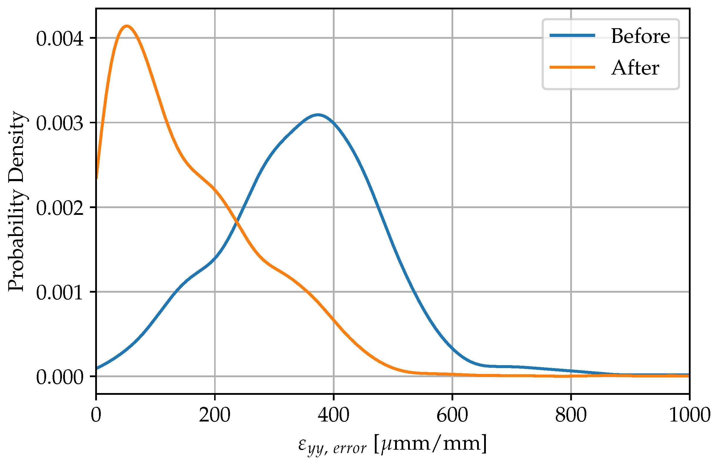
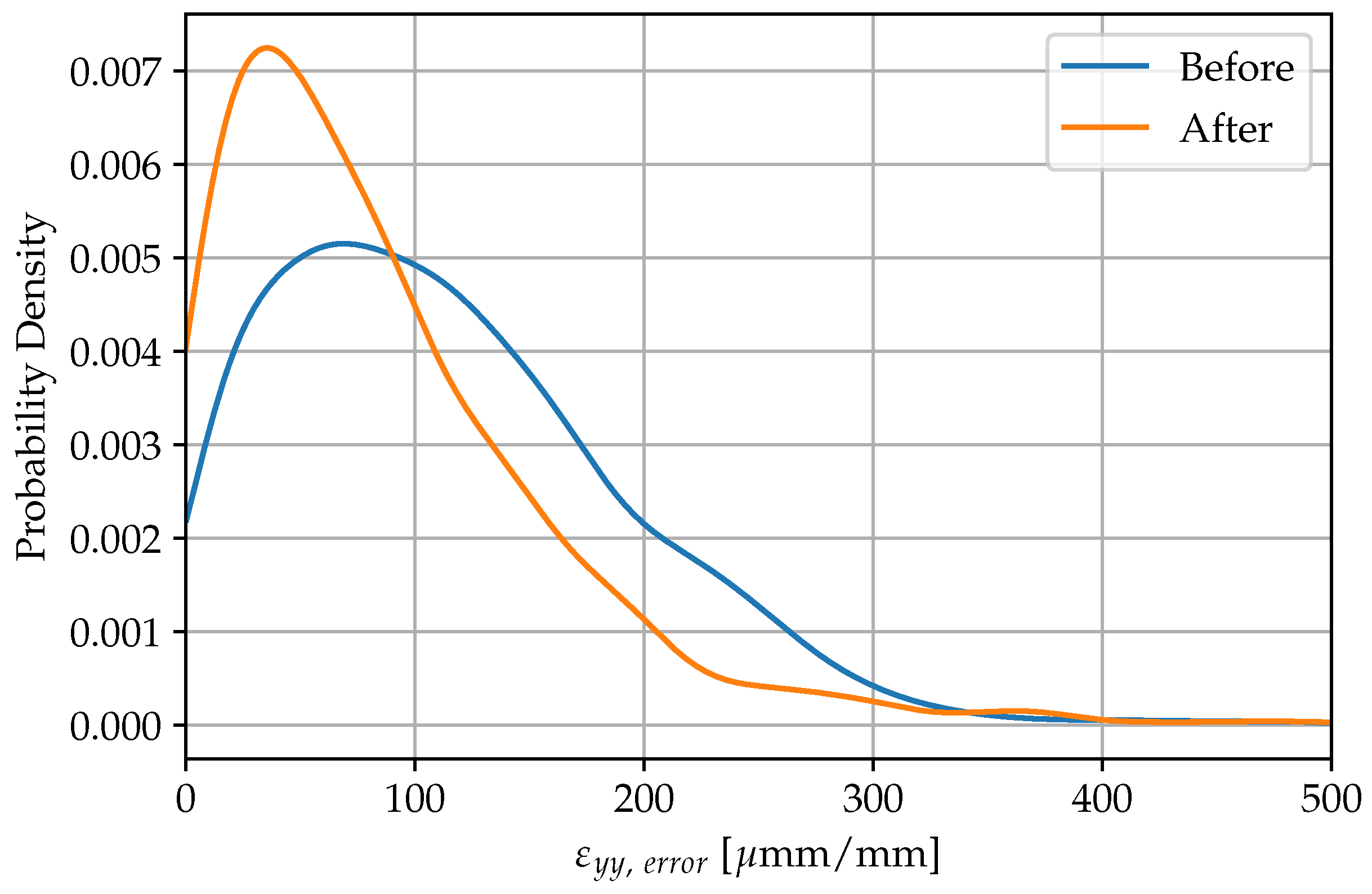
![Mca 28 00040 g009]() The improvement in accuracy is also shown in Figure 10 where the probability density histogram shifted to the left-hand-side of the plot and the width of the peak is reduced. This indicates that the probability density of the errors close to the experiment’s 2D-DIC noise-floor both increased and became more concentrated after the error compensation method was applied.Figure 10. A histogram showing the change in the probability density of the error from the application of the error compensation method. This data is also for the 700th image of Test 1.Figure 10. A histogram showing the change in the probability density of the error from the application of the error compensation method. This data is also for the 700th image of Test 1.
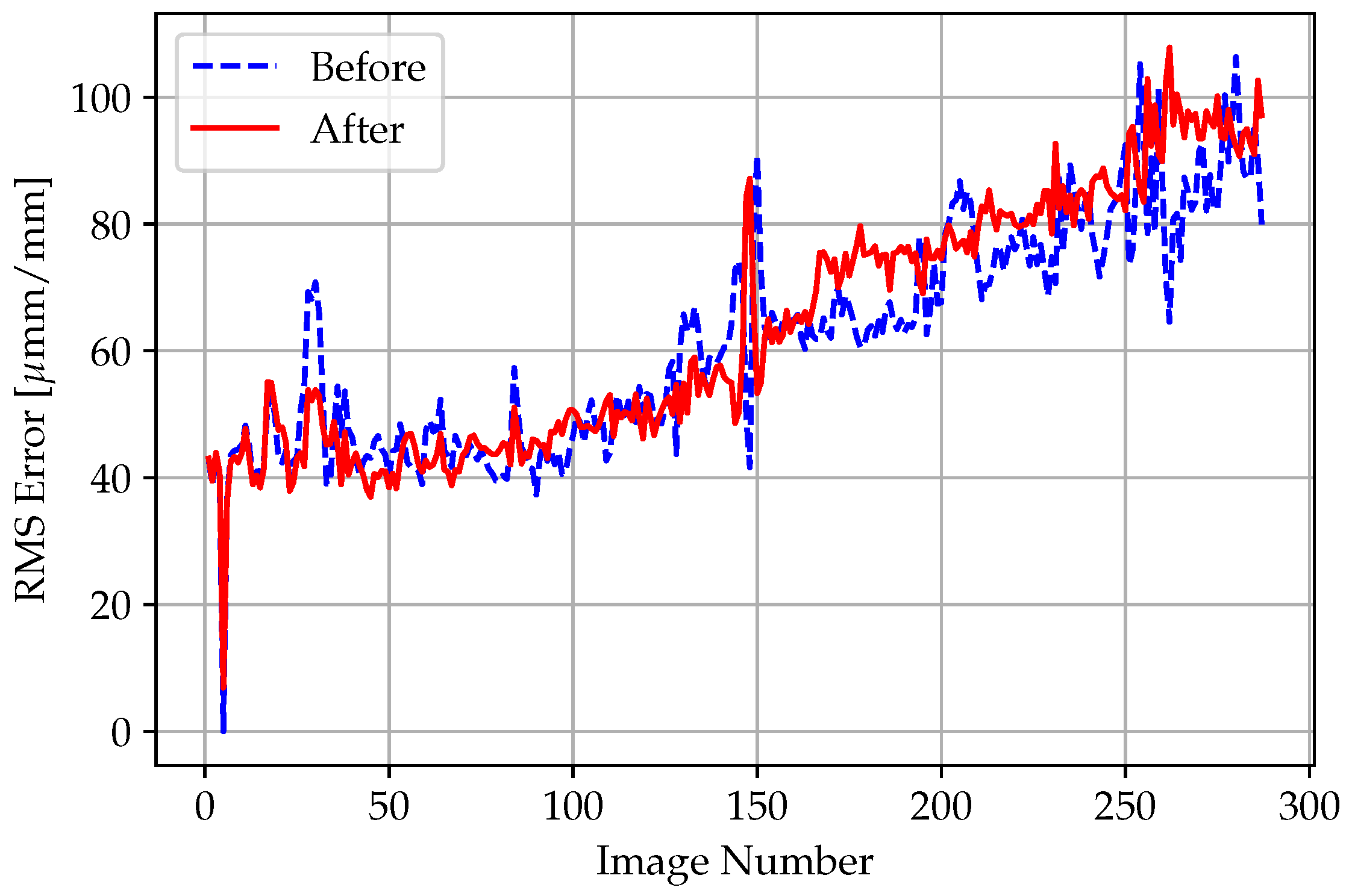
The improvement in accuracy is also shown in Figure 10 where the probability density histogram shifted to the left-hand-side of the plot and the width of the peak is reduced. This indicates that the probability density of the errors close to the experiment’s 2D-DIC noise-floor both increased and became more concentrated after the error compensation method was applied.Figure 10. A histogram showing the change in the probability density of the error from the application of the error compensation method. This data is also for the 700th image of Test 1.Figure 10. A histogram showing the change in the probability density of the error from the application of the error compensation method. This data is also for the 700th image of Test 1.![Mca 28 00040 g010]() The line plot in Figure 11 is included here to demonstrate that the error was successfully compensated for in the entire measurement (and not only for a single image).Figure 11. The RMS strain error between the stereo-DIC and 2D-DIC measurements, before and after the error compensation was applied, for Test 1.Figure 11. The RMS strain error between the stereo-DIC and 2D-DIC measurements, before and after the error compensation was applied, for Test 1.
The line plot in Figure 11 is included here to demonstrate that the error was successfully compensated for in the entire measurement (and not only for a single image).Figure 11. The RMS strain error between the stereo-DIC and 2D-DIC measurements, before and after the error compensation was applied, for Test 1.Figure 11. The RMS strain error between the stereo-DIC and 2D-DIC measurements, before and after the error compensation was applied, for Test 1.![Mca 28 00040 g011]()
- Test 2: Similarly, the 2D-DIC measurement accuracy of Test 2 substantially improved because of the error compensation method, which can be seen in Figure 12. The appearance of the corrected 2D-DIC contour plot again approaches that of the stereo-DIC contour plot in comparison to the contour plot of the uncorrected 2D-DIC data. An improvement in accuracy is seen in how the magnitude of the majority of the strain error values also decreased between the contour plots of the |Error| Before and After Correction.Figure 12. Contour plots of the stereo-DIC, 2D-DIC, corrected 2D-DIC and error data for the 700th image of Test 2.Figure 12. Contour plots of the stereo-DIC, 2D-DIC, corrected 2D-DIC and error data for the 700th image of Test 2.
![Mca 28 00040 g012]() Figure 13 also shows the improved accuracy of the 2D-DIC data as a result of the error compensation method, in the same way that Figure 10 does.Figure 13. A histogram showing the change in the probability density of the error from the application of the error compensation method. This data is also for the 700th image of Test 2.Figure 13. A histogram showing the change in the probability density of the error from the application of the error compensation method. This data is also for the 700th image of Test 2.
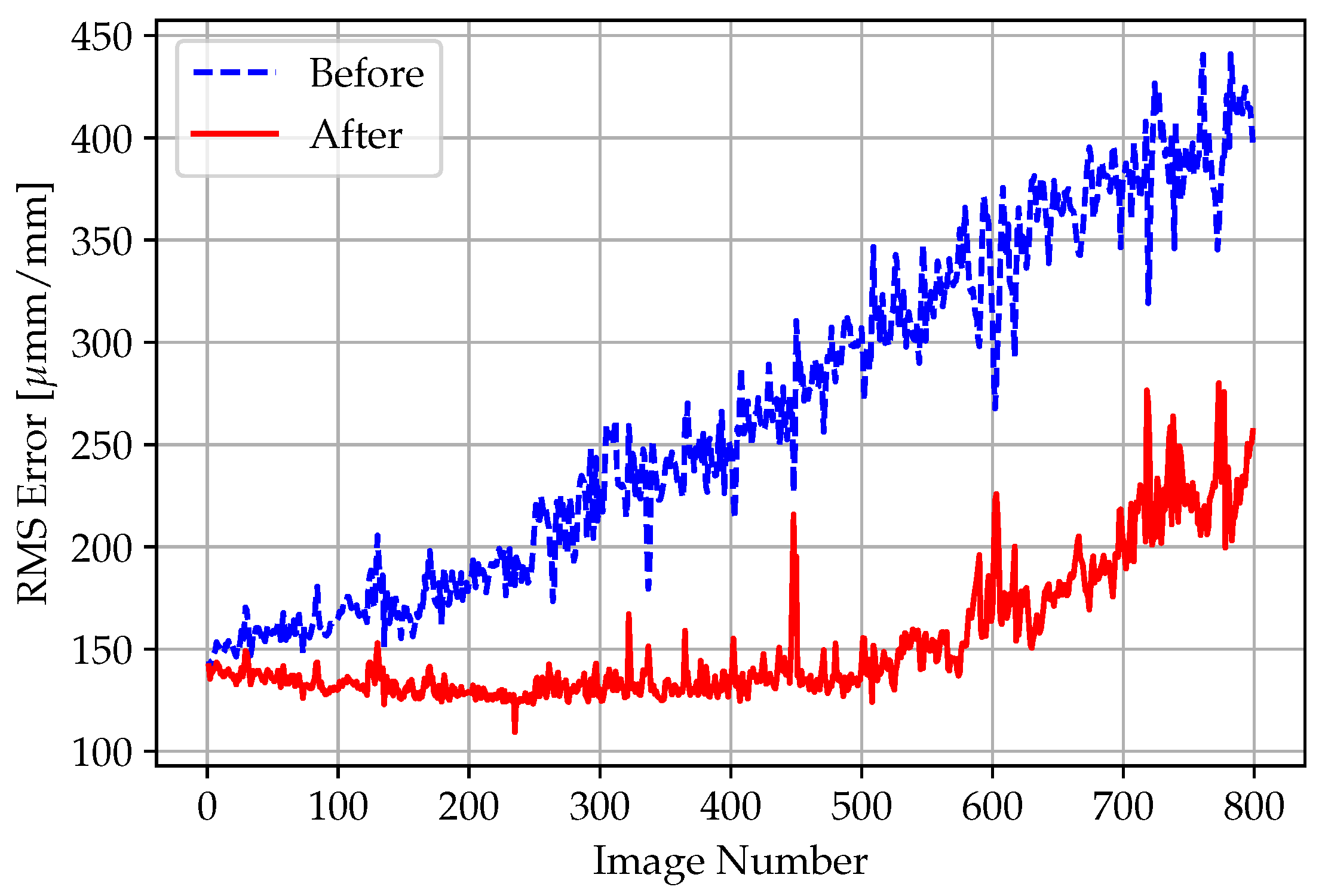
Figure 13 also shows the improved accuracy of the 2D-DIC data as a result of the error compensation method, in the same way that Figure 10 does.Figure 13. A histogram showing the change in the probability density of the error from the application of the error compensation method. This data is also for the 700th image of Test 2.Figure 13. A histogram showing the change in the probability density of the error from the application of the error compensation method. This data is also for the 700th image of Test 2.![Mca 28 00040 g013]() As before, the line plot in Figure 14 is presented here as it shows that the strain error was compensated for in the entire DIC measurement.
As before, the line plot in Figure 14 is presented here as it shows that the strain error was compensated for in the entire DIC measurement. - Test 3: Unlike in Tests 1 and 2, the error compensation method did not produce a considerable improvement in the 2D-DIC measurement accuracy. The strain error was indeed reduced in Test 3, as shown in Figure 15, although this reduction is relatively minor compared to that of Tests 1 and 2. Both in the case of the appearance of the 2D-DIC contour plots (before and after correction), and in the case of the decrease in the magnitude of the strain error values in the |Error| plots (before and after correction), a relatively small improvement in accuracy is still noticeable here.Figure 14. The RMS strain error between the stereo-DIC and 2D-DIC measurements, before and after the error compensation was applied, for Test 2.Figure 14. The RMS strain error between the stereo-DIC and 2D-DIC measurements, before and after the error compensation was applied, for Test 2.
![Mca 28 00040 g014]() Figure 15. Contour plots of the stereo-DIC, 2D-DIC, corrected 2D-DIC and error data for the 700th image of Test 3.Figure 15. Contour plots of the stereo-DIC, 2D-DIC, corrected 2D-DIC and error data for the 700th image of Test 3.
Figure 15. Contour plots of the stereo-DIC, 2D-DIC, corrected 2D-DIC and error data for the 700th image of Test 3.Figure 15. Contour plots of the stereo-DIC, 2D-DIC, corrected 2D-DIC and error data for the 700th image of Test 3.![Mca 28 00040 g015]() Correspondingly, the probability density histogram, shown in Figure 16, also did not show a large improvement in the 2D-DIC measurement accuracy. Even though the histogram’s left-hand-side shift was not as drastic as in Test 1 and 2, the peak of the histogram for Test 3 clearly increased and moved closer to the 2D-DIC noise-floor. This shows that the strain errors were indeed reduced.Figure 16. A histogram showing the change in the probability density of the error from the application of the error compensation method. This data is also for the 700th image of Test 3.Figure 16. A histogram showing the change in the probability density of the error from the application of the error compensation method. This data is also for the 700th image of Test 3.
Correspondingly, the probability density histogram, shown in Figure 16, also did not show a large improvement in the 2D-DIC measurement accuracy. Even though the histogram’s left-hand-side shift was not as drastic as in Test 1 and 2, the peak of the histogram for Test 3 clearly increased and moved closer to the 2D-DIC noise-floor. This shows that the strain errors were indeed reduced.Figure 16. A histogram showing the change in the probability density of the error from the application of the error compensation method. This data is also for the 700th image of Test 3.Figure 16. A histogram showing the change in the probability density of the error from the application of the error compensation method. This data is also for the 700th image of Test 3.![Mca 28 00040 g016]() Although it is not as clear here as it was in Test 1 and 2, Figure 17 shows that a slight improvement in 2D-DIC accuracy was obtained over the entire measurement.Figure 17. The RMS strain error between the stereo-DIC and 2D-DIC measurements, before and after the error compensation was applied, for Test 3.Figure 17. The RMS strain error between the stereo-DIC and 2D-DIC measurements, before and after the error compensation was applied, for Test 3.
Although it is not as clear here as it was in Test 1 and 2, Figure 17 shows that a slight improvement in 2D-DIC accuracy was obtained over the entire measurement.Figure 17. The RMS strain error between the stereo-DIC and 2D-DIC measurements, before and after the error compensation was applied, for Test 3.Figure 17. The RMS strain error between the stereo-DIC and 2D-DIC measurements, before and after the error compensation was applied, for Test 3.![Mca 28 00040 g017]()


4. Discussion
5. Conclusions
Author Contributions
Funding
Data Availability Statement
Conflicts of Interest
Abbreviations
| DIC | Digital Image Correlation |
| 2D | Two-Dimensional |
| 3D | Three-Dimensional |
| OPM | Out-of-Plane Motion |
| SG | Strain Gauge |
| VSG | Virtual Strain Gauge |
| RMS | Root-Mean-Square |
| ROC | Region of Compensation |
References
- Peters, W.H.; Ranson, W.F. Digital Imaging Techniques In Experimental Stress Analysis. Opt. Eng. 1982, 21, 213427. [Google Scholar] [CrossRef]
- Libertiaux, V.; Pascon, F.; Cescotto, S. Experimental verification of brain tissue incompressibility using digital image correlation. J. Mech. Behav. Biomed. Mater. 2011, 4, 1177–1185. [Google Scholar] [CrossRef] [PubMed]
- Van Rooyen, M.; Becker, T.; Westraadt, J.; Marx, G. Creep Damage Assessment of Ex-Service 12% Cr Power Plant Steel Using Digital Image Correlation and Quantitative Microstructural Evaluation. Materials 2019, 12, 3106. [Google Scholar] [CrossRef] [PubMed] [Green Version]
- Walley, J.L.; Wheeler, R.; Uchic, M.D.; Mills, M.J. In-Situ Mechanical Testing for Characterizing Strain Localization During Deformation at Elevated Temperatures. Exp. Mech. 2012, 52, 405–416. [Google Scholar] [CrossRef]
- Pan, B.; Qian, K.; Xie, H.; Asundi, A. Two-dimensional digital image correlation for in-plane displacement and strain measurement: A review. Meas. Sci. Technol. 2009, 20, 062001. [Google Scholar] [CrossRef]
- Hijazi, A.L. A Novel Approach for the Determination of Surface Tilt Angles in Two-Dimensional Digital Image Correlation Experiments. Exp. Mech. 2020, 60, 267–282. [Google Scholar] [CrossRef]
- Pan, B.; Yu, L.; Wu, D.; Tang, L. Systematic errors in two-dimensional digital image correlation due to lens distortion. Opt. Lasers Eng. 2013, 51, 140–147. [Google Scholar] [CrossRef]
- Sutton, M.A.; Yan, J.H.; Tiwari, V.; Schreier, H.W.; Orteu, J.J. The effect of out-of-plane motion on 2D and 3D digital image correlation measurements. Opt. Lasers Eng. 2008, 46, 746–757. [Google Scholar] [CrossRef] [Green Version]
- Pan, B.; Yu, L.; Wu, D. High-accuracy 2D digital image correlation measurements using low-cost imaging lenses: Implementation of a generalized compensation method. Meas. Sci. Technol. 2014, 25, 025001. [Google Scholar] [CrossRef]
- Wittevrongel, L.; Badaloni, M.; Balcaen, R.; Lava, P.; Debruyne, D. Evaluation of Methodologies for Compensation of Out of Plane Motions in a 2D Digital Image Correlation Setup. Strain 2015, 51, 357–369. [Google Scholar] [CrossRef]
- Xu, X.; Zhang, Q.; Su, Y.; Cai, Y.; Xue, W.; Gao, Z.; Xue, Y.; Lv, Z.; Fu, S. High-Accuracy, High-Efficiency Compensation Method in Two-Dimensional Digital Image Correlation. Exp. Mech. 2017, 57, 831–846. [Google Scholar] [CrossRef]
- Lava, P.; Coppieters, S.; Wang, Y.; Houtte, P.V.; Debruyne, D. Error estimation in measuring strain fields with DIC on planar sheet metal specimens with a non-perpendicular camera alignment. Opt. Lasers Eng. 2011, 49, 57–65. [Google Scholar] [CrossRef]
- Pan, B.; Yu, L.; Wu, D. High-Accuracy 2D Digital Image Correlation Measurements with Bilateral Telecentric Lenses: Error Analysis and Experimental Verification. Exp. Mech. 2013, 53, 1719–1733. [Google Scholar] [CrossRef]
- Jähne, B. Practical Handbook on Image Processing for Scientific and Technical Applications, 2nd ed.; CRC Press: Boca Raton, FL, USA, 2004. [Google Scholar]
- ASTM E8/E8M; Standard Test Methods for Tension Testing of Metallic Materials. ASTM International: West Conshohocken, PA, USA, 2021.


| Cameras | LaVision Imager M-lite 5M |
| Image resolution | 2464 × 2056 pixels |
| Lenses | RICOH FL-CC3516-2M TV LENS |
| Focal length | 35 mm |
| Field-of-view | Simple specimen tests: 90.7 × 108.8 mm; Complex specimen tests: 121.7 × 145.8 mm |
| Image scale | Simple specimen tests: 23.3 pixels/mm; Complex specimen tests: 17.3 pixels/mm |
| Stand-off distance | Simple specimen tests: 430.85 mm; Complex specimen tests: 654.58 mm |
| Image acquisition rate | 10 Hz |
| Lighting | White linear LED arrays |
| Aperture | Simple specimen tests: f/4.5; Complex specimen tests: f/7 |
| Patterning method | Matte white spray painted-base coat, matte black spray painted-speckles |
| Approximate pattern feature size (major diameter) | Simple specimen tests: 3–21 pixels (0.13–0.90 mm); Complex specimen tests: 3–30 pixels (0.17–1.73 mm) |
| Software | LaVision DaVis 10.2.1 |
| Subset size | Simple specimen tests: 61 pixels (2.62 mm); Complex specimen tests: 61 pixels (3.53 mm) |
| Step size | Simple specimen tests: 20 pixels (0.86 mm); Complex specimen tests: 20 pixels (1.16 mm) |
| Subset shape function | Affine |
| Strain formulation | Engineering strain |
| Virtual strain gauge size | Simple specimen tests: 139.8 × 65.24 pixels (6 × 2.8 mm) 1; Complex specimen tests: 103.8 × 48.44 pixels (6 × 2.8 mm) 1 |
| Strain noise floor | Simple specimen tests: stereo-DIC—41.3 μmm/mm, 2D-DIC—39.6 μmm/mm; Complex specimen tests: stereo-DIC—47.6 μmm/mm, 2D-DIC—30.6 μmm/mm |
| Strain bias | Simple specimen tests: stereo-DIC—3.6 μmm/mm, 2D-DIC—9.3 μmm/mm; Complex specimen tests: stereo-DIC—−2.1 μmm/mm, 2D-DIC—−1.7 μmm/mm |
| Out-of-plane motion strain bias | Simple specimen tests: 1972 μmm/mm per mm; Complex specimen tests: 1535 μmm/mm per mm |
Disclaimer/Publisher’s Note: The statements, opinions and data contained in all publications are solely those of the individual author(s) and contributor(s) and not of MDPI and/or the editor(s). MDPI and/or the editor(s) disclaim responsibility for any injury to people or property resulting from any ideas, methods, instructions or products referred to in the content. |
© 2023 by the authors. Licensee MDPI, Basel, Switzerland. This article is an open access article distributed under the terms and conditions of the Creative Commons Attribution (CC BY) license (https://creativecommons.org/licenses/by/4.0/).
Share and Cite
Visser, C.-H.; Venter, G.; Neaves, M. A Strain-Gauge-Based Method for the Compensation of Out-of-Plane Motions in 2D Digital Image Correlation. Math. Comput. Appl. 2023, 28, 40. https://doi.org/10.3390/mca28020040
Visser C-H, Venter G, Neaves M. A Strain-Gauge-Based Method for the Compensation of Out-of-Plane Motions in 2D Digital Image Correlation. Mathematical and Computational Applications. 2023; 28(2):40. https://doi.org/10.3390/mca28020040
Chicago/Turabian StyleVisser, Carl-Hein, Gerhard Venter, and Melody Neaves. 2023. "A Strain-Gauge-Based Method for the Compensation of Out-of-Plane Motions in 2D Digital Image Correlation" Mathematical and Computational Applications 28, no. 2: 40. https://doi.org/10.3390/mca28020040