1. Introduction
Cerebrospinal fluid (CSF) is a clear, proteinaceous fluid essential for maintaining homeostasis of the central nervous system (CNS) [
1,
2]. It acts as a shock absorber for the CNS, cushioning the brain within the skull [
3,
4,
5]. CSF provides hydromechanical protection via multiple functions: buoyancy of the brain, spinal cord, and nerves; volume adjustment in the cranial cavity; brain volume regulation via osmoregulation, and a buffering effect against external forces [
1]. In the average adult human, there is an estimated 150 mL of CSF circulating at any given moment. The traditional model of CSF production states that 20% of CSF comes from the brain parenchyma with the majority (80%) produced by the choroid plexus and secreted into the ventricular cavities [
2,
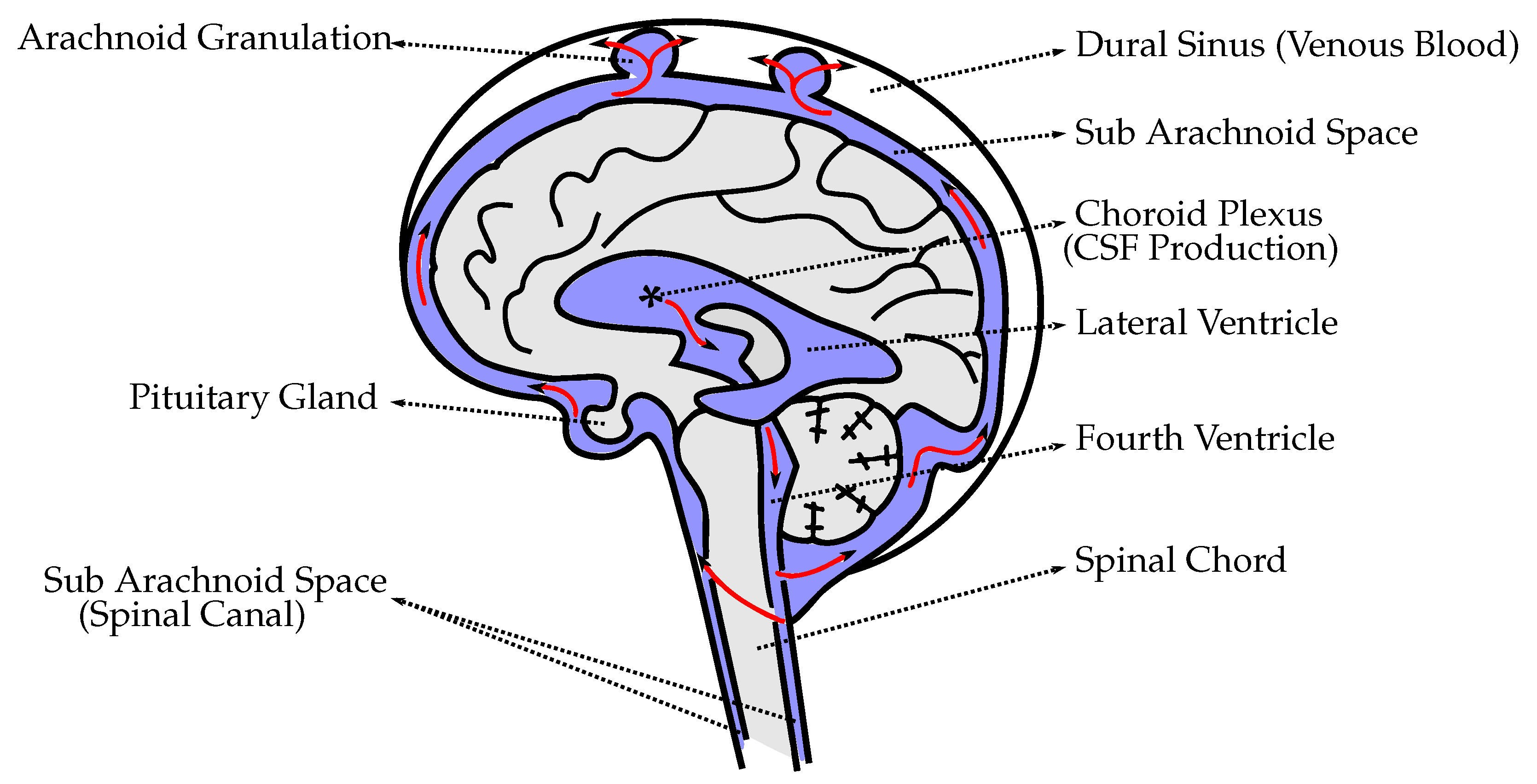
6]. CSF fills this system of cavities at the center of the brain and the subarachnoid space surrounding the brain and spinal cord (
Figure 1) dissipating downward forces acting on the brain and reducing mechanical stress [
7,
8].
There are three published constitutive models representing CSF behavior: solid-like, viscoelastic, and fluid-like. However, all represent solid material models with varying material properties. The solid-like constitutive model represents CSF as a linear and nearly incompressible elastic solid with a bulk modulus much larger than the shear modulus [
9,
10]. The viscoelastic CSF constitutive model is a linear viscoelastic model with shear relaxation behavior [
11,
12]. The fluid-like CSF utilizes an elastic solid material with fluid-like constitutive behavior and an equation of state constitutive model [
13]. In recent years, many groups have shifted to the use of fluid-structure interaction (FSI) models [
14,
15,
16,
17,
18]. Since the start of this project, recent work has shown that others are also attempting to use similar numerical methods to simulate FSI of CSF with brain, but with geometrically simplified 2D models [
19]. The Arbitrary Lagrangian–Eulerian (ALE) formulation has also been used to model the CSF interaction with brain structures [
14]. The accuracy of ALE methods depends on the use of meshes with high density, which can be a problem in modelling the small gap between the skull and highly detailed brain geometry. The use of ALE brings additional complications to models which contain detailed anatomy such as gyri and sulci. For example, ALE methods are either strongly coupled, or weakly coupled. Weakly coupled ALE methods are known for accuracy issues and their inability to perform well when attempting to parallelize the algorithms. Strongly coupled ALE methods yield large ill-conditioned system matrices, i.e., system matrices that are prone to large numerical errors with each system-solving iteration within each non-linear iteration within each time-step [
20].
While the importance of including CSF in the numerical simulations is now well-documented [
21], the current finite element studies reported in the literature often lack more detailed anatomical structures [
12,
14,
15,
22,
23,
24,
25]. The brain is more complex in structure than what has been described in prior models. For example, CSF is commonly presented as existing only outside of the brain, i.e., between the skull and a single solid mass representing the brain. The model presented in this study is an FSI model which uses fluid material properties to represent the CSF, replicating fluid found in the brain parenchyma, skull, and ventricular system, as well as including all major anatomical features of the brain [
16,
17,
18,
26]. A detailed analysis of the CSF cushioning mechanism and its impact in mitigating stress and pressure inflicted on brain tissue is useful for the treatment and prevention of brain injuries. The importance of studying CSF interaction with brain parenchyma, and its implication on human diseases such as traumatic brain injury and hydrocephalus [
27], is axiomatic.
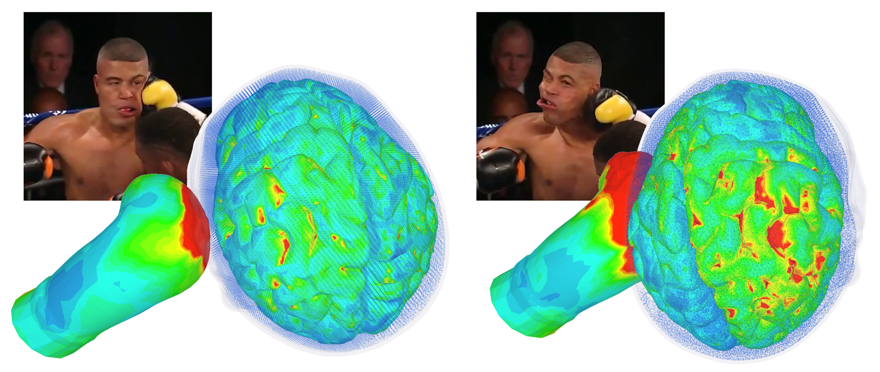
In this study we look at the mechanics of interaction between CSF and brain parenchyma in the context of coup-contrecoup injuries obtained during a direct impact to the head. Most boxing-related brain injuries result from a coup-contrecoup type of injury. Coup injury occurs at the point of impact and, as the brain rebounds, contrecoup injury typically occurs on the opposite side of impact. In this model one particular punch is studied. It is known that this punch has resulted in knockout. It occurred during a match between G. Lorenzo and D. Jacobs on August 19, 2013. The resulting dual impacting of the brain into the skull, i.e., coup-contrecoup injury, is demonstrated.
2. Methods
2.1. Smoothed-Particle Hydrodynamics
Smoothed-particle hydrodynamics (SPH) is a mesh-free, particle-based method for computational fluid dynamics. In each time step, the velocity governs the movement of the particles. Acceleration is computed with a momentum equation. Density and pressure are calculated with a continuity equation and an equation of state. Variables needed, namely density, pressure and velocity, are interpolated using shape functions called kernels. For each particle, the interpolation is performed across a certain range of neighboring particles yielding a weighted sum. Numerically, the SPH method is advantageous in comparison to mesh-based methods. There are no convergence problems associated with large deformations. Biomedical applications are typically exposed to large deformation.
As stated above, the fluid in the SPH method is modeled using discrete particles that are moving with its flow. Each particle is defined by its position and carries a set of physical properties. At each time step, these properties are interpolated between particles found in the vicinity of the investigated location. Let
A be a property evaluated at point
, the interpolation can then be derived from an integral interpolation
where
W denotes a weighting function also called the smoothing kernel. The property
A is weighted with
W and integrated over
. The smoothing kernel
W is a function of the vector from the integration variable
to the investigated point
as well as a smoothing length
h. While the smoothing length can be considered as a variable it is further assumed to be constant. Moreover, assuming that
W is rotationally symmetrical and introducing the normalized variable
,
becomes dependent upon
q only. The
has to fulfill the following properties:
The first condition states that the weighting has to be positive. The second condition states that the weighting has to decrease with increasing distance of the investigated point. The third condition represents a normalization ensuring the integral conservation of A over the interpolation process.
2.2. Head Model
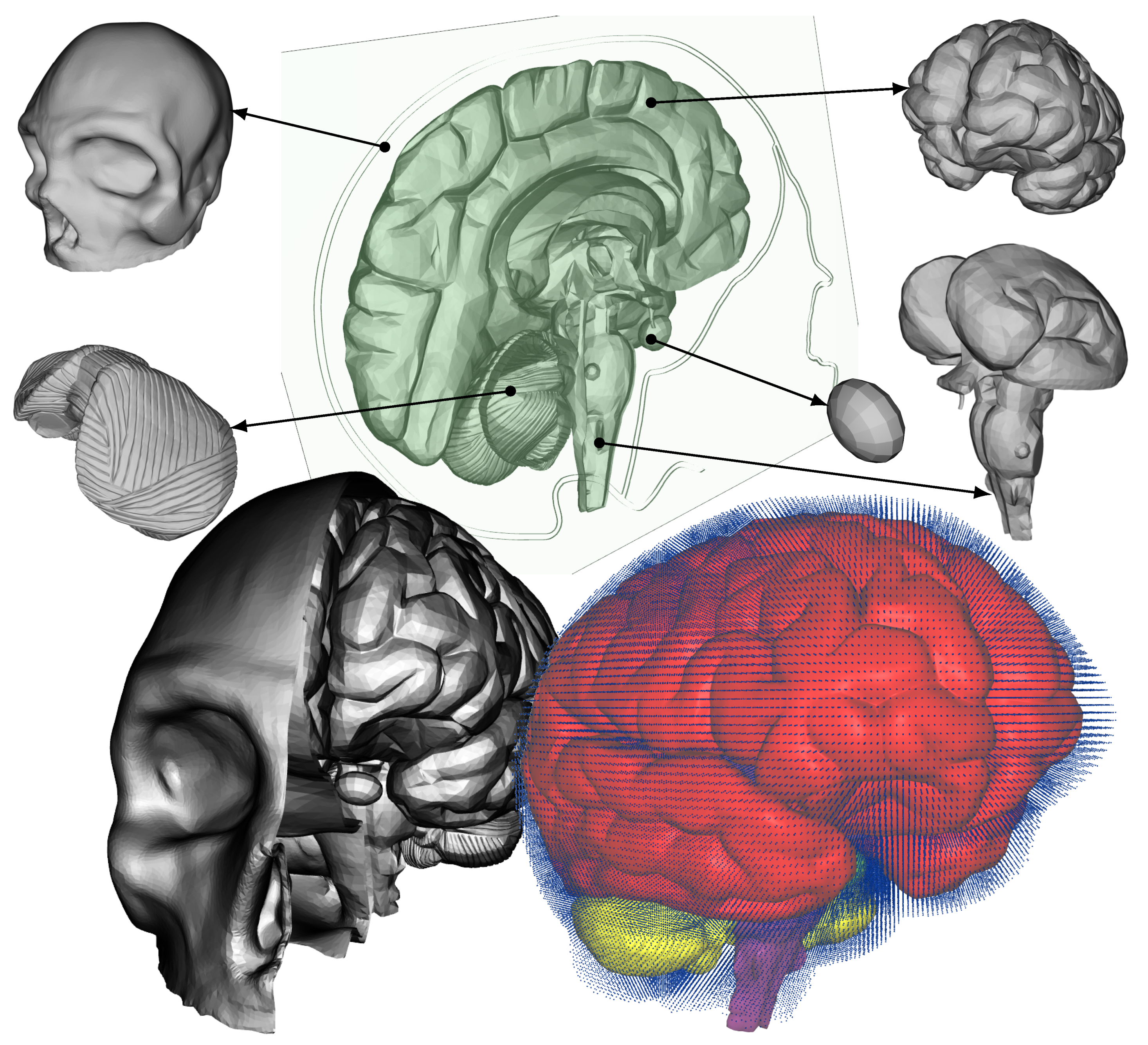
The five distinct anatomical structures used in this model are shown in
Figure 2. The skull, cerebrum, cerebellum, pituitary gland, and brainstem each have unique material properties. The patient-specific model is based on the Digital Imaging and Communications in Medicine (DICOM) images acquired from an online database. Anatomical features missing in this model include the skin, spinal cord, meninges, and the arachnoid granulation,
Figure 1. When compared to the very short impact impulse time history used in these simulations, the CSF flow in the head can be neglected, too. The CSF flow is relatively slow, 0.05–0.08 m·s
, i.e., during the impact impulse time history the CSF flows by 0.2–0.3 mm. These assumptions also make the presence of the granulations negligible.
2.3. Loading Conditions
The power of a punch can be calculated in terms of explosive power, i.e.,
of TNT (trinitrotoluene). It takes 1
g of TNT to produce an energy of 4184
or 429
, equal to the power necessary to move 429
of mass with the speed of 1 m·s
. The speed, force and weight of the boxer are the three main factors that determine the force of a blow to the head. Other factors include how heavy the boxer’s hands and gloves are, and how rigidly the boxer holds their wrist. The blows in a professional boxing match are powerful and can introduce peak translational acceleration of 58
g to the head [
28]. The maximum power that is generated in a boxer blow is around 750
of force at the heavyweight category and achieved by some of the hardest hitting boxers in history. Average boxers, depending on their height and weight, could deliver punches with up to 600
of force (5884
N), equivalent to 1.4
g of TNT [
29].
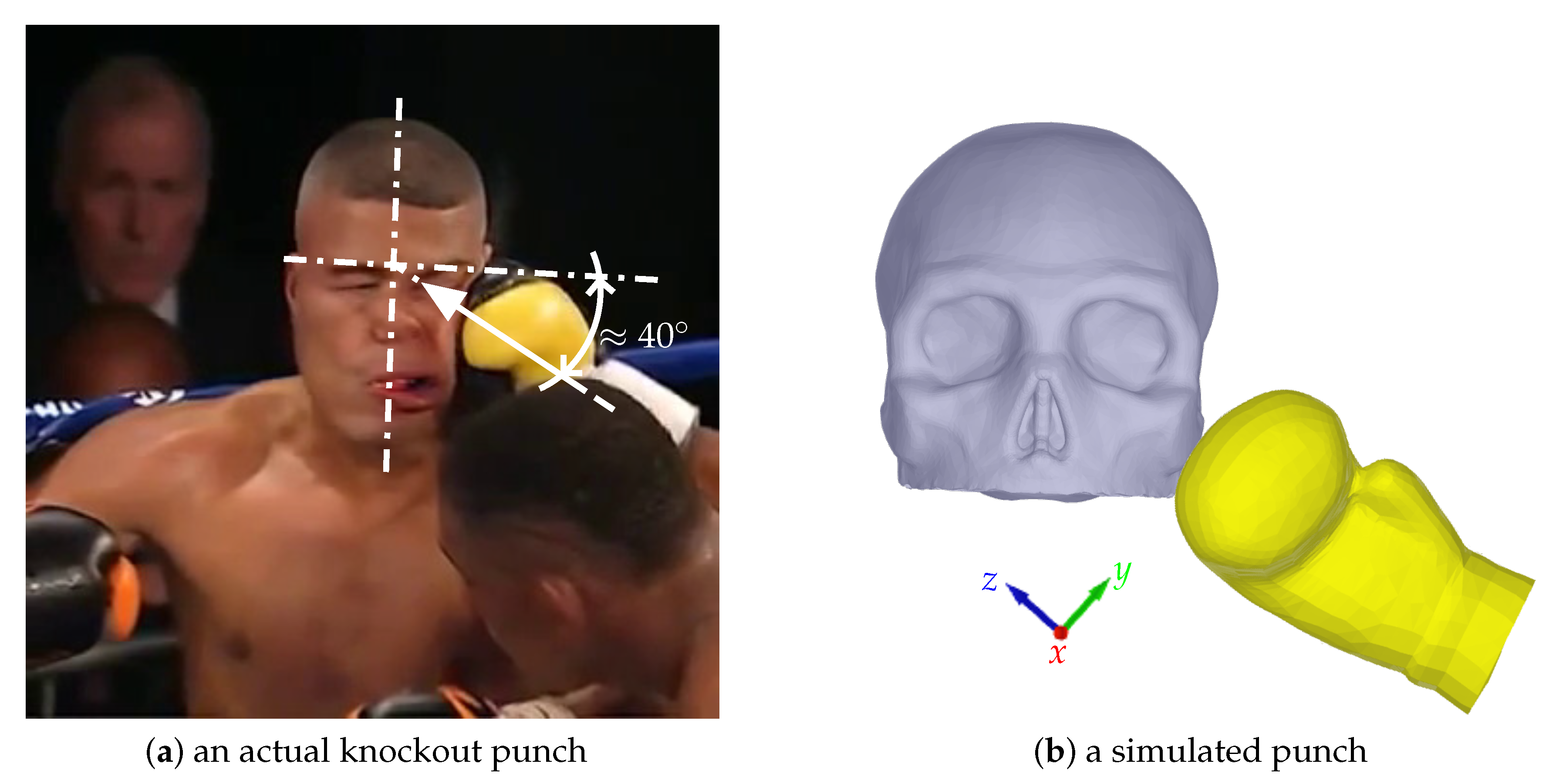
A model of an actual boxing glove is used to deliver the blow to the head model containing the CSF. A speed of 10 m·s
is prescribed to the rigid-solid part that fills the inside of the glove [
30]. A slow-motion video of a knockout punch between D. Jacobs and G. Lorenzo (19 August 2013) is used to extract the direction and location of the punch (
Figure 3a). The blow is delivered at a 40
angle to the head, an angle found in the majority of punches resulting in a knockout (≈45
). Foam material properties are prescribed to the glove elements. The simulations become more complex that way but it guarantees more realistic outcome (
Figure 3b). The subsequent rotation of the head after the blow is determined by the shape and material of the glove as well, not just by the direction and speed of the force.
2.4. Computer Simulations
The model is comprised of 5 parts. The skull is assigned rigid material properties with density 1900 kg·m
[
31]. Data from studies characterizing the macroscopic physical characteristics of the brain show that it is a viscoelastic material [
32]. The cerebrum, cerebellum, pituitary gland, and brainstem are simulated using a non-linear elastic constitutive material model with varying material properties based from the literature [
33,
34,
35,
36,
37]. The cerebrum, cerebellum, brainstem, and pituitary gland are each composed of a different number of tetrahedral elements; 96,385, 40,808, 18,634, 310, respectively. The CSF was modeled using the SPH method with the bulk modulus of 21.9 GPa [
12] and density 1000 kg·m
[
38]. The number of fluid particles filling the subarachnoid space between the skull and brain, and other cavities, is 94,690.
The IMPETUS Afea Finite Element and SPH solvers® (IMPETUS Afea AS, Norway) were used to model the impact scenario. Fluid motion and boundary interaction calculations were solved with the IMPETUS Afea SPH Solver, while large deformations in the solid parts were simultaneously solved with the IMPETUS Afea Solver. Both the solvers use a commodity GPU for parallel processing. All solid elements were fully integrated, removing the possibility of hourglass modes and element inversion that plagues the classic under-integrated elements. Both fluid and solid domains and their interaction were solved with an explicit integration scheme. All simulations were solved on a standard workstation. Parallel acceleration was achieved with a Tesla K40 GPU with 12 GB of Graphic DDR memory and 2880 CUDA Cores.
The contact, i.e., particle to structure contact, is very simple which is why SPH is ideal for these complex applications because it can easily account for movement in any direction, as opposed to finite element fluid solvers which involve more complicated contact and usually require remeshing of the fluid domain during the simulation. The fact that IMPETUS can allow for a very high resolution in terms of particle density provides for a very accurate particle to structure contact, especially with such a detailed and complex structure as the brain. The other critical part of the simulation is the structural model. The IMPETUS Aset® Element Technology provides high order tetrahedron elements that are accurate for nonlinear dynamic response. This allows for automeshing complicated structures such as those found in biomedical applications. The accuracy of these elements has been demonstrated in many commercial applications when compared with hexahedron elements and is very accurate in bending and plasticity.
To confirm that convergence was reached, h-refinement of the finite element mesh was performed, and the solution was found to yield same results. Similarly, smaller number of fluid particles was used to obtain results within 5% of the values obtained with the higher number of particles. The above stated number of particles, 94,690, is high considering that the volume of the cavities and subarachnoid space is much smaller than rest of the model. This confirmed that the results are converged. Our prior publication describes the SPH equations in greater detail [
39]. The SPH method is chosen for this study because traditional FSI techniques can be computationally expensive and challenging regarding their parallelization [
20]. In order to use traditional FSI techniques, geometrical simplifications would need to occur, and the anatomical accuracy would have to be sacrificed. Moreover, in recent years the SPH has been increasingly used in biomedical applications [
40].
3. Results
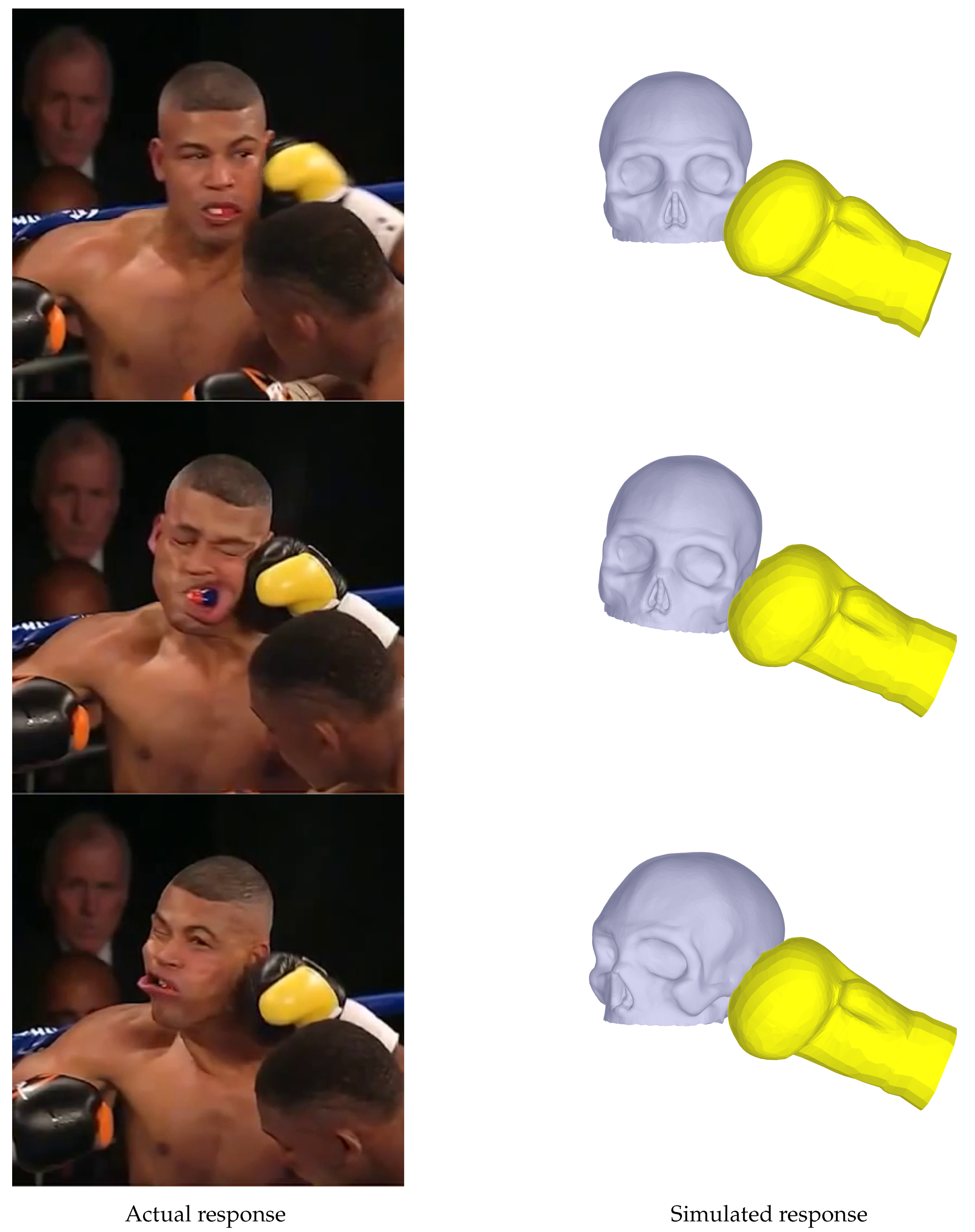
While the pressure response in the CSF in a head exposed to trauma has been previously validated against cadaveric experiments [
17,
18], for the given scenario the dynamic response of the head to the punch had to be validated as well. The response of the head model to the simulated punch is compared with the head movement resulting from the actual punch in
Figure 4. As the resulting head movement of the actual boxer taking the punch matches the resulting head model movement from the simulated punch, the subsequent results from the CSF interacting with the brain structures can now be analyzed. The coup-contrecoup injuries after the simulated knock-out punch are depicted in
Figure 5. The contrecoup injury, located in the right parietal and occipital lobes, appear to be more severe than the coup injury.
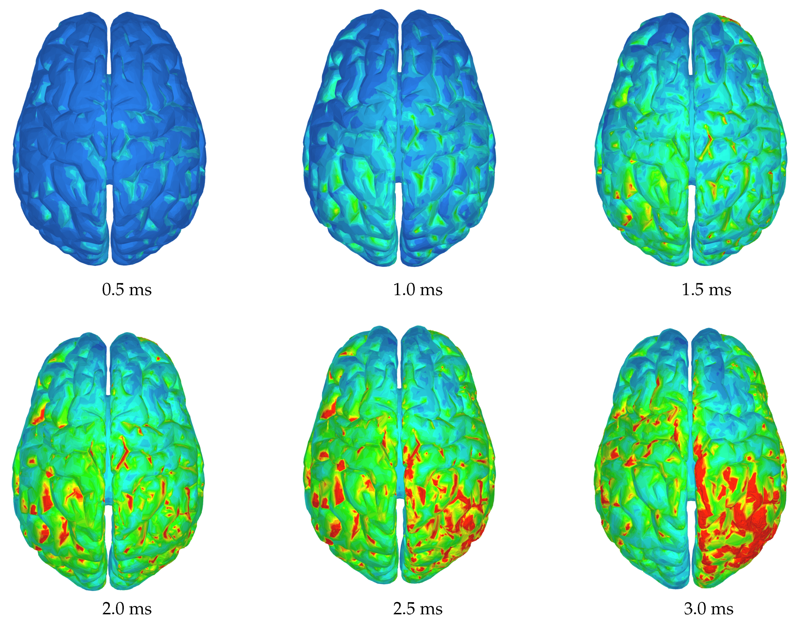
Figure 6 shows six time instances of stress values seen from the superior view. It can be observed that while the punch was introduced to the left zygomatic bone (cheekbone) of the skull, the main primary (coup) injury can be found in the left posterior temporal lobe. The maximum stress values in the left temporal lobe keep increasing until about 2.5
after the first contact of the glove with the skull and spread forward towards the anterior temporal lobe, until they dissipate at around 3
. The time point of 3
is when the secondary (contrecoup) injury reaches its maximum values. The contrecoup injury can be located primarily in the right occipital lobe. After the last time point shown the contrecoup injury also begins to dissipate, see
Figure 7.
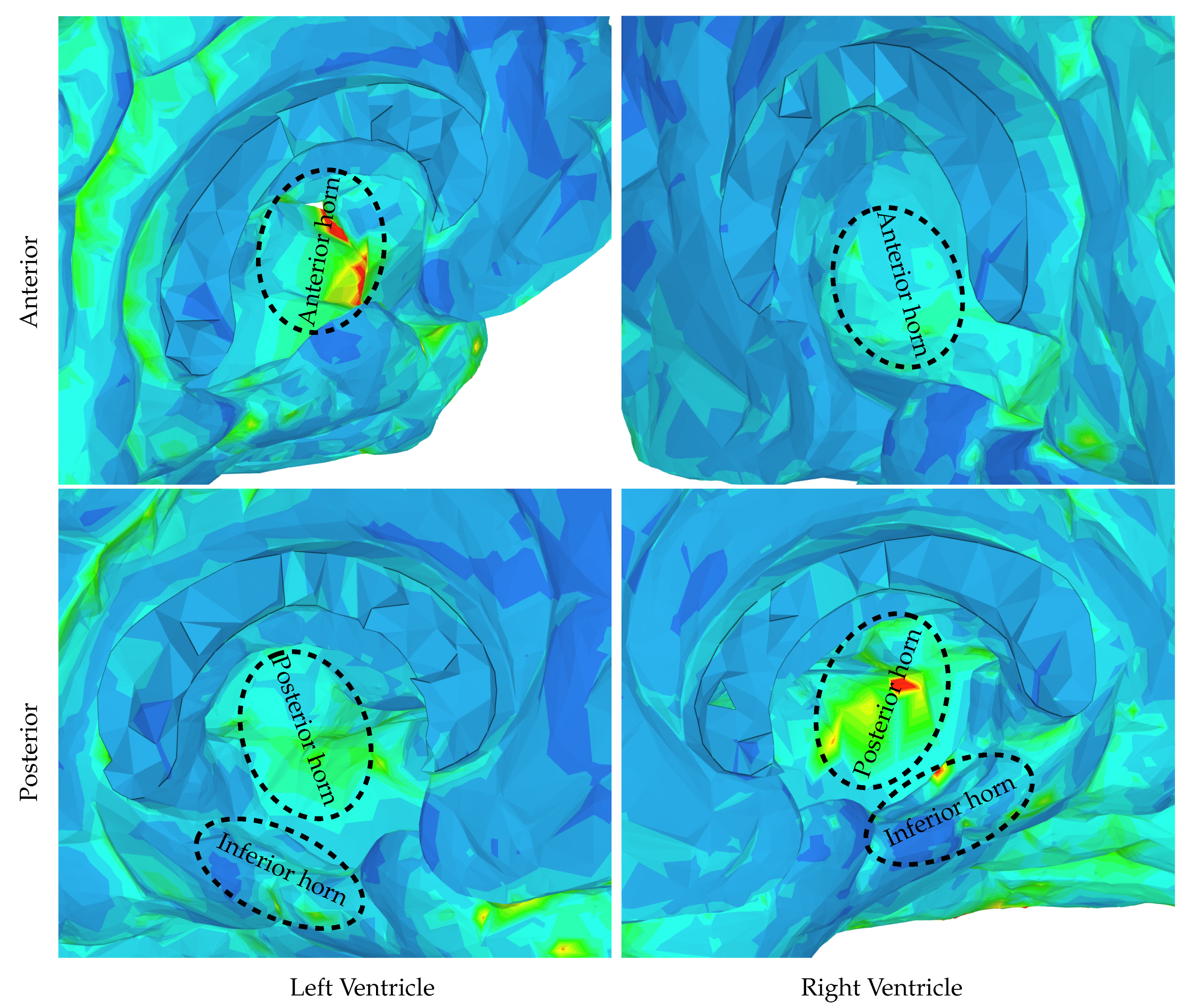
The majority of CSF is produced by the choroid plexus in the lateral, third, and fourth ventricles [
2]. The ventricular system transports CSF around the cranial cavity with the assistance of ciliated ependyma that beat in synchrony [
2]. A disease called post-traumatic hydrocephalus is when CSF builds up in the ventricles after a traumatic brain injury, resulting in increased intracranial pressure [
41]. The excessive accumulation of CSF surrounding the brain can be due to a multitude of factors: overproduction of CSF, blockage of normal CSF flow, or insufficient absorption resulting in fluid accumulation [
2,
42]. The response of lateral ventricles to the knockout punch is shown in
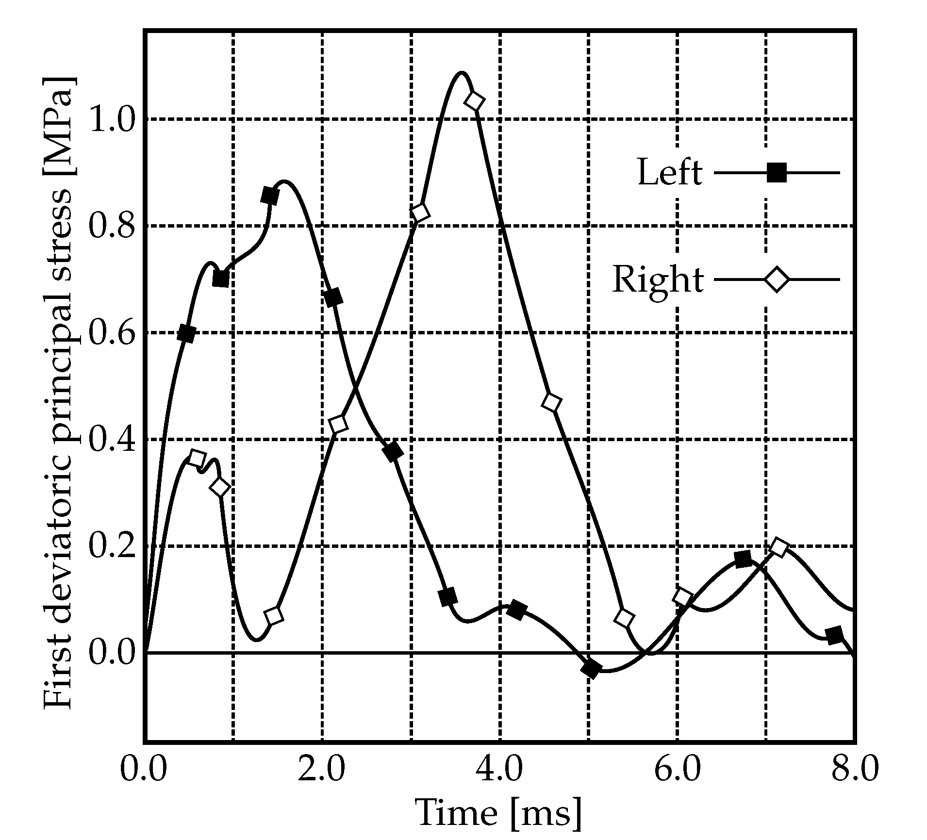
Figure 8. As seen in
Figure 5, the response to the contrecoup injury is more severe than the response to the coup injury,
Figure 8 additionally shows the first deviatoric principal stress in the ventricles at the moment when the brain rebounds within the skull. High levels of stress can be found in the anterior and posterior horns of the left and right ventricles, respectively. Similarly, the coup-contrecoup injuries in the brain stem, after the simulated knock-out punch, are depicted in
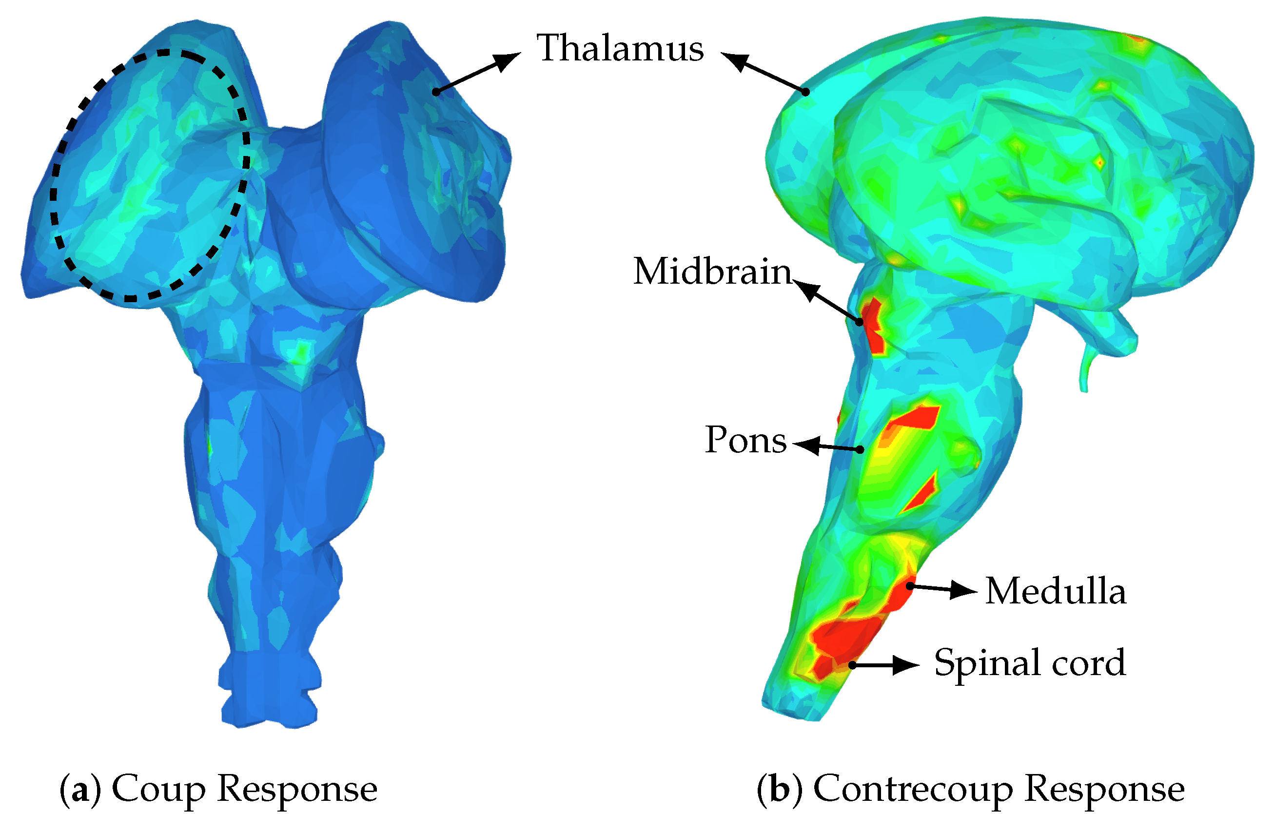
Figure 9. Again, the contrecoup injury appear to be more severe than the coup injury. The coup injury is located in the left thalamus whereas the contrecoup injury is located in the right midbrain, pons, medulla and spinal cord.
4. Conclusions
The mechanism of the coup and contrecoup injuries sustained in a knock-out punch is shown. The brain regions most affected are the parietal and occipital lobes after the brain rebounded inside the skull, i.e., contrecoup injury. The damage associated with the regions most affected in the given trauma (
Figure 5) can yield difficulties with co-ordinating sensory information, perception, spatial relationships, recognizing faces and objects, responding to internal sensations (i.e., damage to parietal lobe) and/or sight (i.e., damage to occipital lobe).
Trauma to the ventricles is also analyzed (
Figure 8) and shows that the highest stress values occur in the anterior and posterior horns of the left and right ventricles, respectively. This can result in CSF build up leading to increased intracranial pressure, a condition called post-traumatic hydrocephalus [
41]. More important is the impact of this damage to the corpus callosum and the ability to predict diffuse axonal injury. Trauma to the ventricles and the white matter alongside the ventricular areas is likely to cause axonal injuries, which can then lead to a wide variety of neurological sequelae such as mood disorders and cognitive impairment [
43]. Damage to the brain stem can also be seen (
Figure 9). The coup injury is located in the left thalamus but it is not as severe as the contrecoup injury which is located in the right brain stem, more precisely the right midbrain, pons, medulla and spinal cord (
Figure 9b). The reticular activating system (RAS) is a network of neurons located in the brain stem. The mechanism of concussion is often defined as dysfunction of the RAS as it is believed to control consciousness.
5. Discussion
Athletes tend to neglect reporting symptoms for various reasons, e.g., not thinking the injury is serious enough to need medical attention (66.4%), a desire to remain in competition (41.0%), and/or lack of awareness of what to consider as a symptom (36.1%) [
44]. Depending on the circumstances leading to a traumatic brain injury, different regions of the brain are affected, thus yielding different sets of possible symptoms. The regions affected cannot be predicted by simply locating the point of impact for the coup injury and the side opposite the area that was hit for the contrecoup injury. The resulting symptoms will also depend on subsequent head rotation, acceleration and deceleration, and whether any protective gear was utilized. Different designs of head protective gears will also yield different results. The latest research shows that the newest helmet designs do not necessarily improve the user’s protection against concussion even when compared with helmets used during the First World War [
45]. One of the ways to use this model is to perform a comparative study between two designs of protective equipments and assess their efficacy. In other words, this model could help in the creation of specialized equipment with a known efficacy in comparison to existing protective equipment.
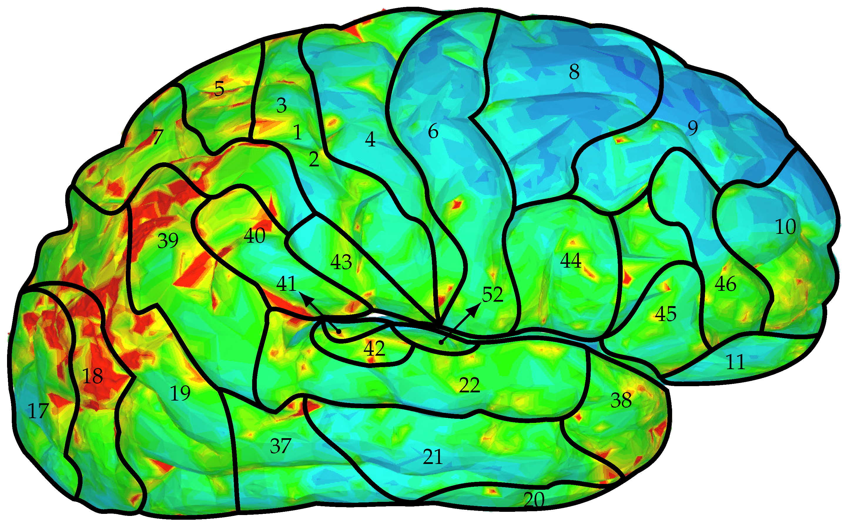
While the relationship between brain structure and function is still debated, the Brodmann’s map of cytoarchitectonics is widely used for that purpose. In
Figure 10 the first deviatoric principal stress at the point when the brain rebounds, i.e., contrecoup injury, is superimposed with the Brodmann’s map. It can be seen that region 18 has the highest area covered by the stress maximum. That region is part of the occipital cortex and is known as the ‘visual association area’ responsible for the interpretation of images. Similarly, region 17 is another area of the brain with high stress levels and is called the ‘primary visual cortex’. It is the part of the visual cortex that receives the visual information coming from the eye. The third area largely affected by the stress exerted on the brain is region 39. Damage to region 39 is associated with semantic aphasia, i.e., inability to comprehend or formulate language.
The ventricles are where CSF is produced and can serve as an important cushion for brain parenchyma when encountering impacts. In
Figure 8, it is shown that certain areas of the ventricles are affected, particularly the anterior horn of the left ventricle and the posterior horn of the right ventricle. These impacts are likely to cause injury to the corpus callosum which contains large numbers of neuronal axons running along these ventricular structures. Damage to the corpus callosum and the underlying white matter can result in diffuse axonal injury, a common consequence of traumatic brain injury. This particular type of trauma has been linked to a variety of neurological symptoms such as mood disorders, inattention, and impulsivity [
43]. Our FSI model could begin to predict and to study these impacts numerically and will have broader implications in studying traumatic brain injury.
Several limitations can be considered. The results presented here are from a single case study. However, in professional boxing, this is a very typical punch that often leads to a knockout. Hence, the same study (roughly) applies to many other reported cases. Moreover, the boxer suffered several other punches before the final knockout punch; these prior punches are not considered in this study. A major limitation of this model is the omission of the cerebral vasculature. The network of arteries and veins significantly alters brain stiffness since it functions as a spring-like suspension system that limits the brain’s motion [
46,
47]. Design of a model that includes the cerebral vasculature is currently under way.
Additionally, we do not wish to claim that this SPH approach is better suited for modeling the CSF than commonly used solid elements in other models. There may be cases where it might be necessary to study the behavior of the fluid in a model using an actual fluid domain. For example, when studying the effect of CSF drainage via ventriculoperitoneal shunt as a form of treatment for hyrocephalus [
27]. Models that utilize solid elements to study the CSF behavior in such conditions could not be used. However, in other more straightforward scenarios, such as traumatic brain injury where a single blow to the head is studied, the use of solid elements is justified when properly validated. It is certainly less computationally expensive than using traditional FSI techniques in order to represent the CSF using fluid domain. Though, compared to the methods used in this study, the use of solid elements to model the CSF does not provide significant advantage in terms of computational cost.


