1. Introduction
Reversible jet fans are present in road tunnels ventilation and garages, underground car parks, fire protection, good air quality systems, etc. They are designed to operate efficiently in both directions and produce adequate jets. Tunnel jet fans are, in fact, a substantial, i.e., core part of the tunnel ventilation, as well in smoke extraction systems. They should combine the highest technical requirements like efficiency and performance, as well as noise emission. Numerous CFD calculations have been performed in order to study the road tunnel ventilation and firefighting systems [
1,
2,
3,
4,
5,
6,
7,
8]. One of the choices for impulse ventilation of the tunnels is jet fan. “Impulse ventilation of tunnels involves the application of one or more jets of air into a tunnel, to drive the airflow in a desired direction. In essence, the kinetic energy of a high-velocity jet is transferred, with various degrees of efficiency, into the kinetic energy of slower-moving tunnel air” [
4]. Therefore, the role of the jet fans is to provide an impulse to the air flow. “The average jet velocity is in the range of 30 to 40 ms
−1” [
4].
Experimental determination of tunnel ventilation axial ducted fan performance using a two-sensor hot wire X-probe with added pair of near-wall positioning pins is presented in [
9]. Experimental results, obtained in the laboratory in the 1:19 scale tunnel, are used for ventilation performance of CFD test in a uni-directional traffic road tunnel [
3,
9,
10]. Proposal for the improvement of CFD models of the tunnel fire development based on experimental data are also reported [
7]. Improvement of the aerodynamic performance of a tunnel ventilation jet fan is performed by the application of multiobjective optimization technique [
11].
Contemporary CFD tools include aerodynamic optimization of axial fan impeller with its blade geometry, guide vanes if they exist, casing and nozzle shapes, etc. Fan energy characteristics, i.e., the aerodynamic fan curves, prior to experiments, could be estimated numerically. Experimental validation could be done according to the international standard ISO 13350 [
12].
Three high pressure reversible fan concepts, like a two-stage counter rotating fan, a single-stage high speed fan and a two-stage fan with a single motor and impeller on each end of the motor shaft are presented in paper [
13].
Paper [
14] presents the designed reversible jet fan, obtained experimental data and CFD results. Reversible aerodynamic design, in fact, limits the maximum fan pressure side [
13]. Paper [
15] presents a numerical optimization procedure for performance improvement of a jet fan. Authors in [
16] point out that aerodynamically desirable axial fan rotor blades, which would have identical aerodynamic performances in both flow directions, are still insufficiently developed. They present a method to profile these blades.
This paper presents a design of the reversible jet fan, geometries of two versions of the casings and experimentally obtained data. The axial fan impeller is the same in both cases, while casings are different. Experimentally determined thrust, after ISO 13350 [
12], power and volume flow rates for various fan rotation speeds in both rotating directions are presented in this paper. The intention was to design the impeller with good characteristics in both rotating directions, so the automatic fan speed control system could adopt the rotation direction depending on draft direction in the car tunnel. This should result in better maintenance of environmental conditions in car tunnels.
2. Reversible Jet Axial Fan Designs
The design is developed in cooperation of the Hydraulic Machinery and Energy Systems Department (HMESD) University of Belgrade Faculty of Mechanical Engineering (UB FME) and company Rudnap Group Minel Kotlogradnja from Belgrade, Serbia, where it was also manufactured. The demand from industry was to develop jet fan prototype with the following characteristics: volume flow rate—
Qp = 17 m
3s
−1, impeller outer diameter—
Da,p = 0.71 m, fan rotation speed
np = 2950 rpm, fan motor power—
Pp = 39 kW and axial force, i.e., thrust—
Fz,p = 938 N. Here, index “p” denotes “prototype”. Axial thrust is calculated using the Equation (4). According to the reference [
4]: “The average jet velocity is in the range of 30 to 40 m/s.” This is, also, fulfilled for this prototype. These conventional jet fans are aligned parallel to the tunnel axis. The maximal achievable thrust (
Fz,p,max) is calculated using Equation (6) in [
4]. This relation could be simplified for the axial fan impeller in a free stream in the following way:
where
ρ is air density,
Aj is the jet fan outlet cross section,
cz,j is the jet axial average velocity and
cz,fs is the free stream velocity, i.e., air velocity in the tunnel in the region without jet fan influence. Of course, the effective thrust is lower and calculated as follows:
where
ηp is the jet fan efficiency, and
ηp,ins is the jet fan installation efficiency. In some cases, it could be assumed that
ηp = 1 [
4]. Installation efficiency depends on the jet fan position in the tunnel. It could be assumed that
ηp,ins = 1, if the jet fan is positioned in the middle of the tunnel, without the influence of other fans, other obstacles, as well as tunnel surfaces [
4]. However, influence of the wall on the propulsion jet is studied in [
16]. Therefore, the installation efficiency (
ηp,ins) could be estimated on the basis of Equation (9) in [
4], which is derived using the experimental data presented in [
17]. In the case of the presented constructions, the guide vanes and slanted silencers do not exist, so the regulation could be performed only by the fan speed rotation number. For the flow direction purpose, the flow straighteners in the “cross” shape are in-built in both silencers. The flow straighteners need to eliminate or, at least, minimize the turbulent swirling flow, which occurs behind the axial fan impellers [
18], and maximize the axial velocity component which generates thrust. The sound power level according to the A-weighting was not experimentally determined.
Jet fan head, i.e., pressure rise, could be determined in the following way:
where the jet fan efficiency could be estimated as
ηp = 55%. Besides Equation (2), thrust could be also determined as follows:
where
cz,p is average axial velocity calculated as
cz,p =
Qp/
A and surface of the cross-section.
The jet fan model parameters are determined on the basis of the similarity law and equality of coefficients such as flow (
φ), head (
ψ), power (
λ) and efficiency (
η). Reversible jet fan model is developed using the following parameters:
Da = 0.5 m (punctually 499.2 mm ± 0.1) and fan power
P = 3 kW. By introducing power coefficient (
λ) as follows:
where
up is circumferential velocity on diameter
Da,p. Equality of these coefficients for the prototype and model lead to the equation:
Flow coefficient is derived, on the basis of kinematic similarity, as follows:
where
Di is hub diameter.
Flow coefficients for the model and prototype are equal:
It is assumed that non-dimensional diameter (
ν), defined as
ν =
Di/
Da, is equal for the model and prototype:
Volume flow rate of the jet fan model could be determined on the basis of Equations (7)–(9) as follows:
Head coefficient (
ψ) is defined after the dynamic similarity as follows:
where
Y is fan head defined in the following way:
where Δ
pt is difference of total pressures after and before the fan, i.e., total pressure rise in the jet fan.
Applying Equations (11) and (12), as well as introducing the equality of model and prototype head coefficients lead to the following expression:
Using Equations (4) and (7), the following expression is derived:
Right hand side of the Equation (14), by assuming that air density is equal, depends only on flow coefficient and dimensionless radius, which are identical for the model and prototype, so the following equation for thrust could be derived:
In this way, all necessary data for jet fan model design are determined.
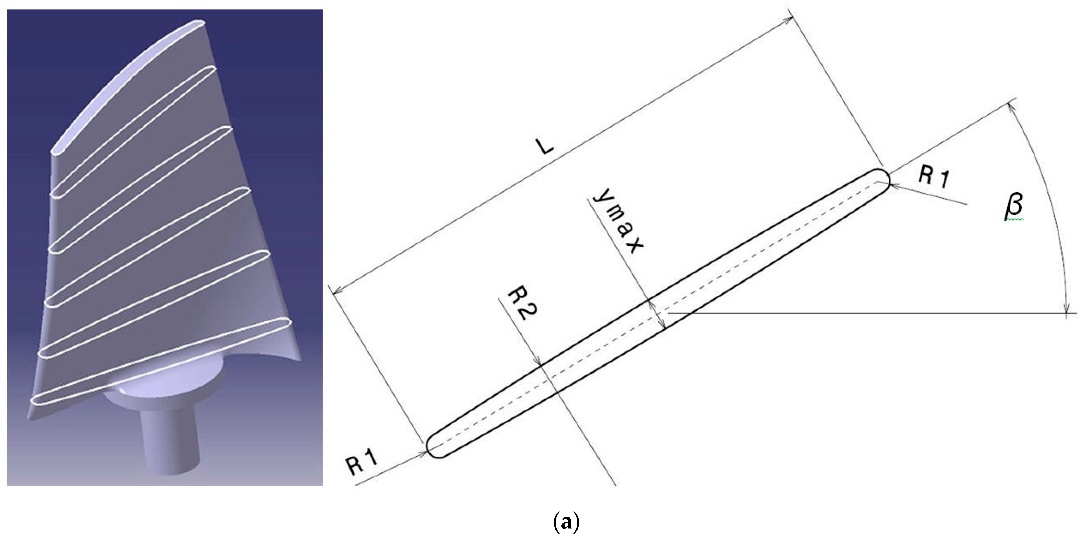
The greatest challenge was to develop axial fan impeller geometry to provide the same energy characteristics in both directions. It is even more important for the reversible axial fan functionality in traffic tunnels where pressure could vary in regions close to the inlet, i.e., exit. In this case, due to the fact that the complete fan construction cannot be rotated, or simpler geometries where blade angles cannot be adjusted, it is clear that axial fan impeller geometry must be symmetrical. This would result in the axial fan impeller with symmetrical blades. They should be designed in the way to use symmetrical airfoil and to be symmetrical to the axis normal to the chord, i.e., in this case, also camber line, which divides it in two halves. The fan is designed after the law of constant head in the radial direction, i.e., constant circulation in order to achieve higher energy efficient fans, i.e., equal energy distribution along the radius. The result is the twisted blade presented in
Figure 1a. Threaded connection M20 is used for blade positioning in the axial fan hub. Six symmetrical profiles and their geometry are shown in
Figure 1a. Geometry parameters for the first and sixth one are presented in
Table 1, where r-radius measured from the axial fan rotation axis, R1—radius at the blade leading/trailing edge, R2—radius of the profile pressure/suction side,
β—profile angle measured from the fan rotation axis and ymax—maximum thickness. Profile maximum thickness is positioned in the center of the straight camber line, which has constant length along the blade
L = 106 mm.
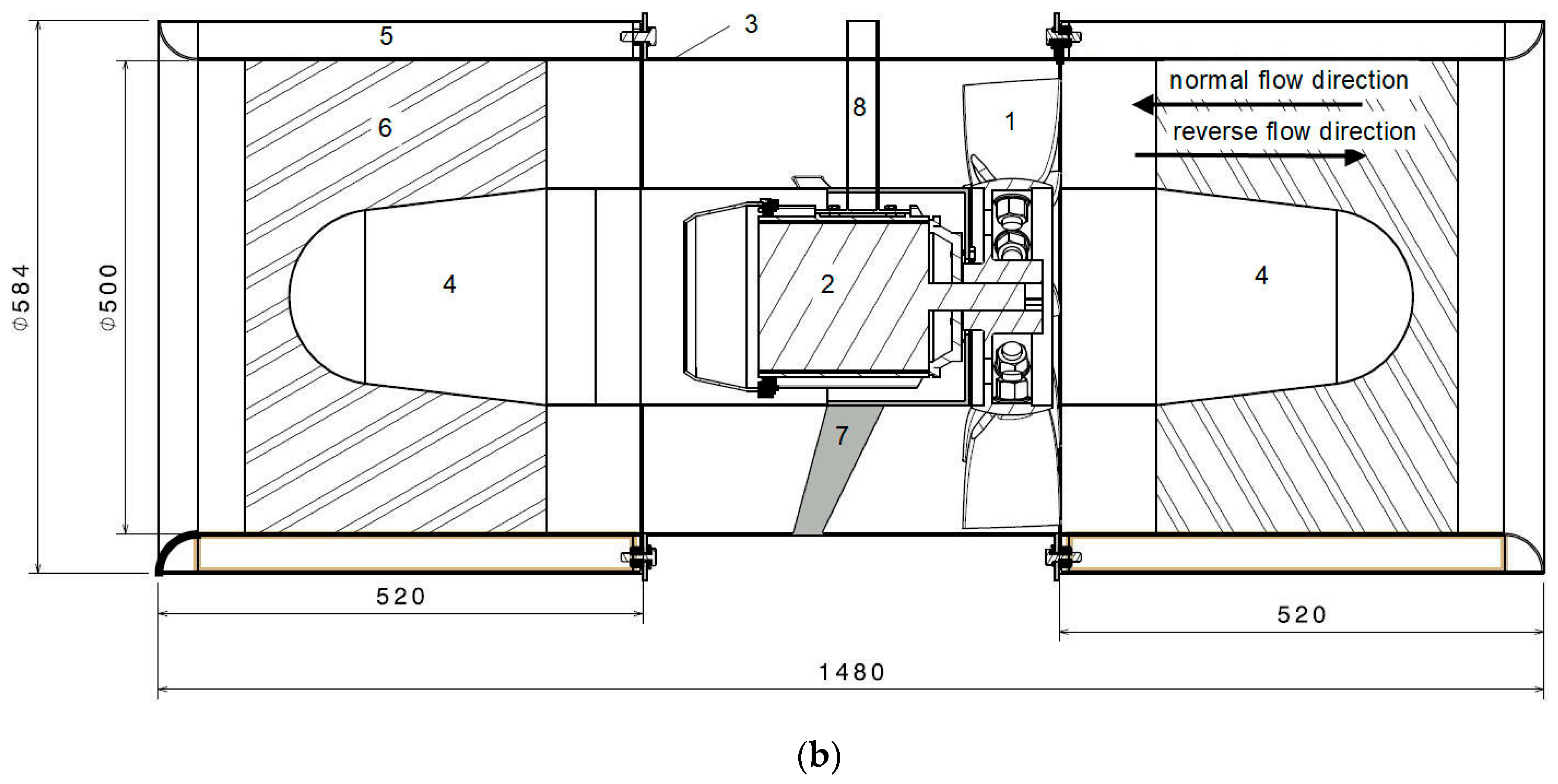
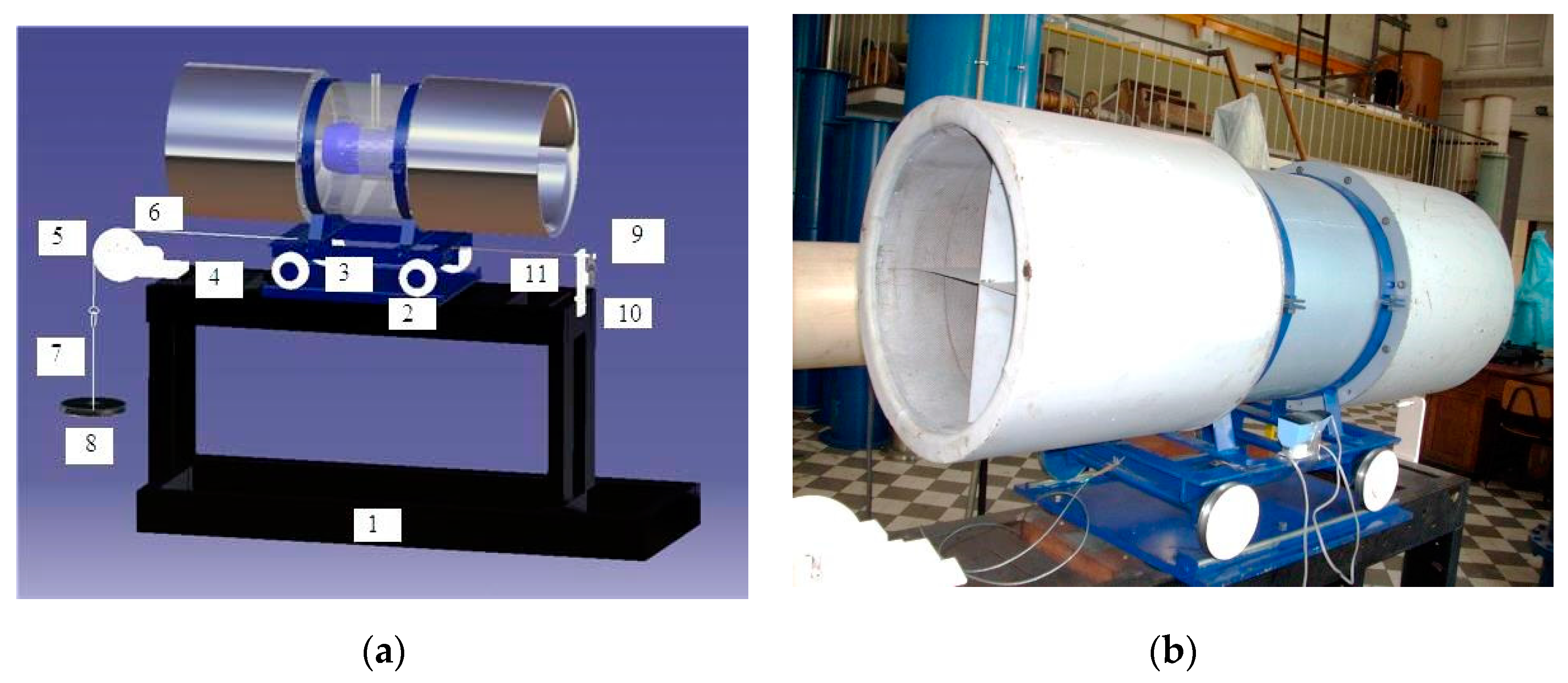
Geometry of the whole construction of the reversible jet axial fan, with specified normal and reversible flow directions, is presented in
Figure 1b, where: 1—impeller, 2—AC motor, 3—impeller casing, 4—profiled impeller hub cap, 5—silencer (sound suppressor), 6—flow straighteners, 7—AC motor support and 8—AC motor cable casing (pipe form). Flow straighteners are not specially profiled, due to the intention to obtain similar flow characteristics in both directions. They are only sheet metal parts which form the “cross” geometry.
Asynchronous electric motor with two poles is placed in the casing in the way not to disturb fluid flow. Axial fan casing with a hub and carrier is designed in the way to stabilize operation and connection with the electromotor.
The jet fan has profiled bell-mouth inlet, and casings have inner diameter of 500 mm, while outer is 584 mm (
Figure 1b). Casing consists of perforated plate, mineral wool and steel plate envelope, which minimize noise. Flow straighteners (
Figure 1b, position 6) decrease generated turbulent swirling flow jet and direct the flow. Namely, the main role is to improve generated jet strength, i.e., maximize thrust and fan efficiency.
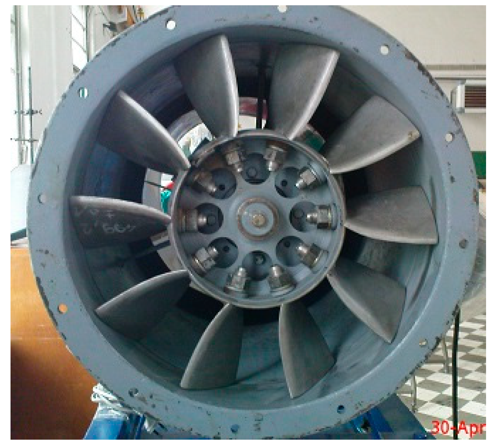
The jet fan model is designed for the following parameters determined above: fan rotation speed—
n = 2251 rpm, volume flow rate—
Q = 4.53 m
3s
−1, impeller outer diameter—
Da = 0.5 m and axial force—
Fz = 130 N. It has ten adjustable blades and dimensionless ratio
ν =
Di/Da = 0.5. The manufactured jet fan model is presented in
Figure 2.
The reversible jet fan 3D model was developed in academic software package CATIA V5R18 (64 bit) for the flow analysis. This model had certain level of “intelligence” based on the CATIA Knowledge tools, which provided blade angle easy variation and blade shape variation according to its angle position. In this way, clearances are minimized.
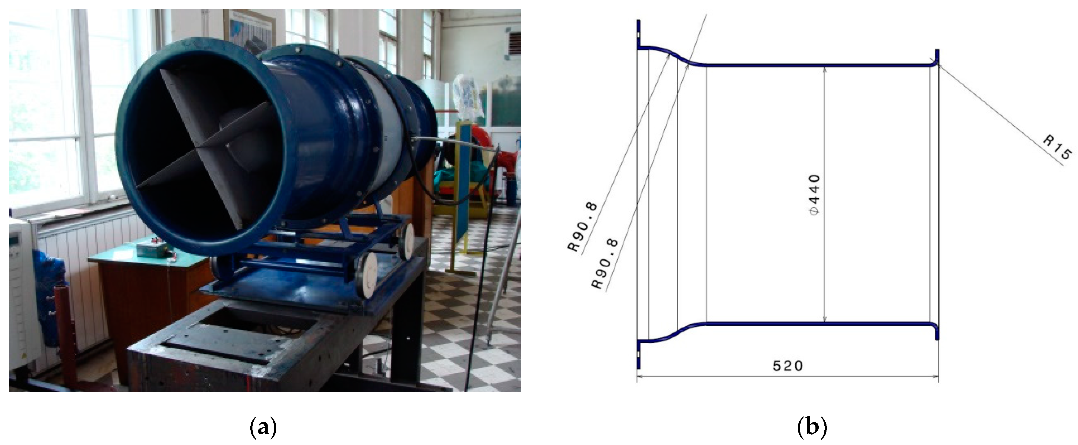
The second construction is with nozzles and flow straighteners as shown in
Figure 3. It has nozzles with inner diameter 440 mm (
Figure 3b).
3. Experimental Test Rig
Experimental investigation of the designed jet fan was conducted on the designed and manufactured thrust measurement table in the Laboratory of the Hydraulic Machinery and Energy Systems Department at the Faculty of Mechanical Engineering University of Belgrade (
Figure 4).
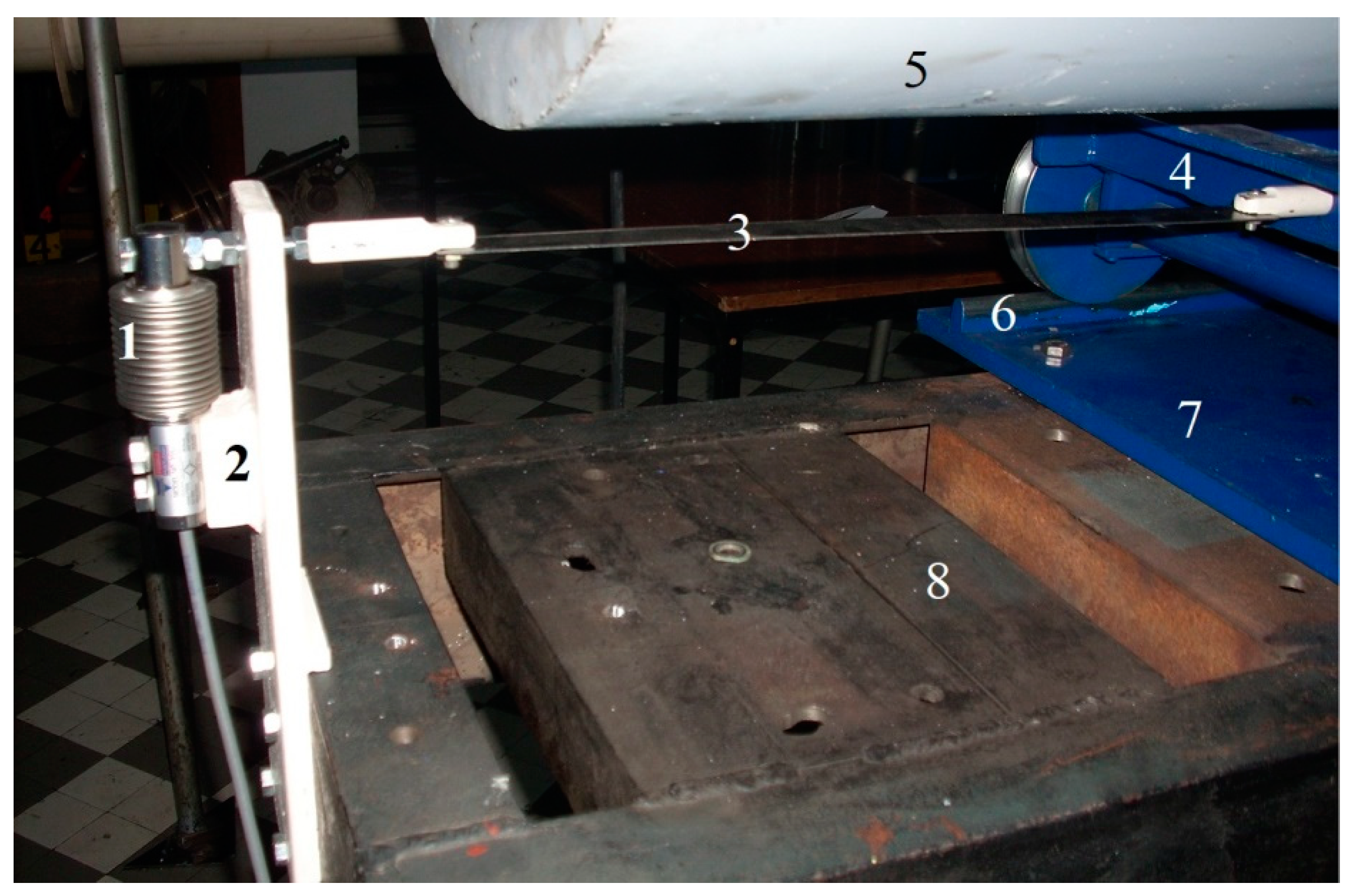
The test rig (
Figure 4), i.e., the thrust measurement table, is composed of numerous elements. The fundament of the test rig construction is manufactured with massive steel U-shaped profiles (
Figure 4a, position 1). It is heavy and provides operating stability important for obtaining precise measuring results. Rails are assembled with the steel plate to the fundament (
Figure 4a, position 2) so that axial fan with wheel chair could safely move along the rails and enable axial force, i.e., thrust measurements (
Figure 4a, position 3). On the measurement table, a wheel fundament is attached, also made of steel. This wheel (pos. 5) is positioned on the wheel fundament (pos. 4) by the axle. Wheel rotation is possible by the use of radial rolling one-row bearing. Steel chrome polished cable with 3 mm in diameter (pos. 6) moves over it and connects weights carrier (pos. 7) with calibrated weights (pos. 8) and wheel chair. Weight carrier has two parts, of which the lower one is used for holding calibrated weights and the upper one is a hook for hanging on the steel rope. It is also calibrated and made of steel. Wheel chair is, on the other side, connected via measuring tape, with a force transducer (pos. 9). This is a construction for force transducer calibration. Calibration preceded each measurement. During measurements the steel cable is dismounted. However, the force transducer is always connected via measuring tape (pos. 11) with the wheelchair, and it is mounted on the steel carrier (pos. 10), which provides appropriate axial force measurements. The Vishay force transducer model 355, type C3, hermetically sealed, was used (
Figure 5, pos. 1). Specified total error is ±0.02% of rated output, which is here for C3, 50 kg, i.e., ±10 g.
A force transducer was carefully calibrated at the thrust measurement table by first loading up to 45 kg and afterwards unloading due to hysteresis determination. A linear characteristic is obtained. A measuring tape transfers axial force from the axial fan to the force transducer. It provides stable work and precise measurements. A signal conditioner is used for the axial force transducer signal conditioning and acquisition. A frequency regulator is used to control the axial fan rotation speed. A digital frequency regulator DS2000, company MOOG, Serbia, was used. It has a three-phase regulator which works over the voltage interval from 65 V till 506 V and frequencies from 50 till 60 Hz. Working temperature interval is 0 till 40 °C. A multifunctional measuring device Testo 450 with appropriate probes was used in these experiments for measuring air temperature and humidity, as well as for velocity measurements with attached vane anemometer probe. On the basis of the velocity measurements, in positions specified by ISO 5801 [
19], the volume flow rate was determined. It is compared with the ones calculated on the basis of the measured axial velocity in the following way:
, where
ρ is air density. A mercury barometer measured atmospheric pressure before each test. Fan rotation speed was determined by a stroboscope DRELLOSCOP 3009.
4. Experimental Results and Discussion
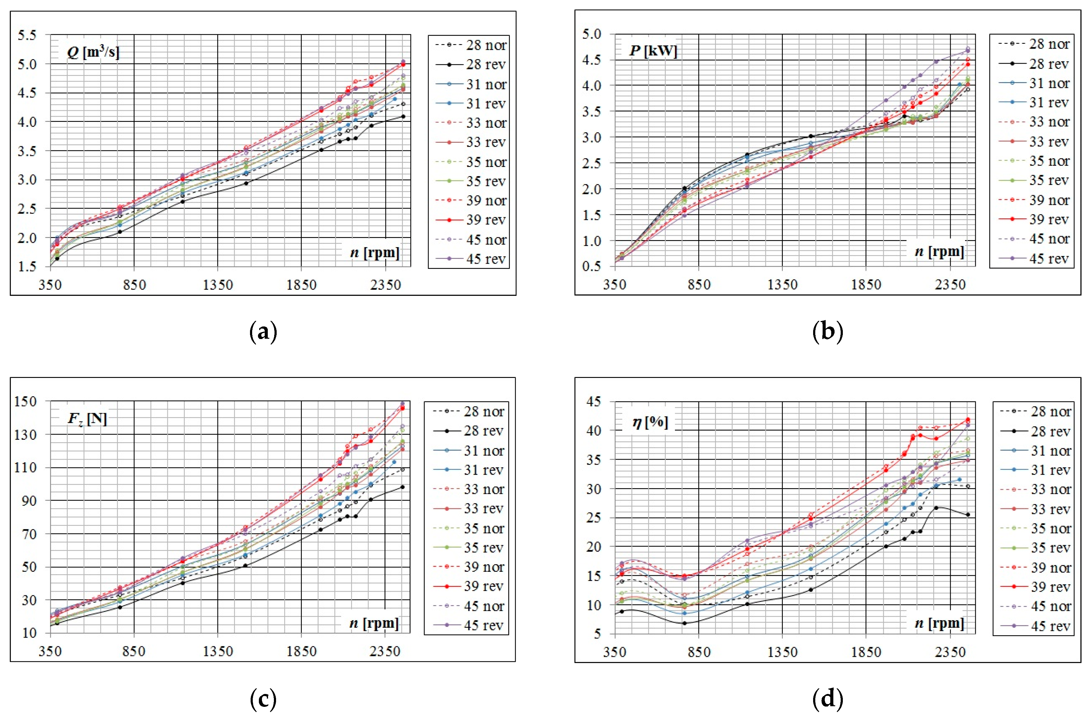
In the conducted experiments, the following physical values have been measured: axial force, i.e., thrust, velocity field at the fan inlet and outlet, fan rotation speed, electromotor power, air temperature, humidity and atmospheric pressure. Measurements were performed for various angle positions of both blade impeller sets, controlled at the outer diameter
Da:
βRa = 28°, 31°, 33°, 35°, 39° and 45° as well as for various fan rotation speeds
n = 400, 800, 1200, 1600, 2080, 2200, 2500 and 2565 rpm. Measurements have also been performed for both fan rotating, i.e., flow directions and are presented in
Figure 6.
The fan efficiency is calculated, only after the contribution of the kinetic energy at the fan outlet, i.e., in the jet, as follows:
where
c is velocity at the fan outlet and
ρ air density. It is assumed that the inlet velocity is zero. It is calculated on the basis of the approximated internal power, presented in
Figure 6b.
All fan characteristics, normally, increase with the fan rotation speed. Hierarchy of increasing the volume flow rate and thrust with increasing the blade angle, up to the angle 39°, is obvious. Fan characteristics depend on flow direction for all angles, but the smallest difference is obtained for angle 39°.
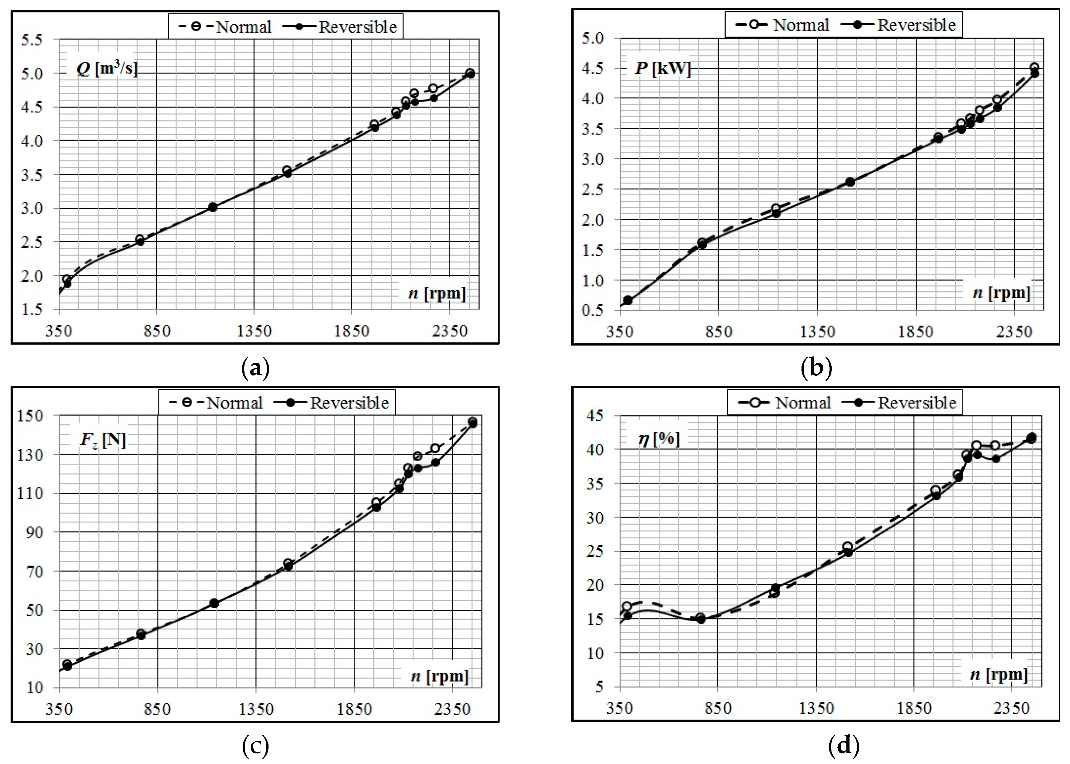
The best angle position (
βRa) of the blade impeller blades is determined on the basis of a large amount of experimental data (
Figure 6). Measuring results for the angle position at the outer diameter
βRa = 39° are presented in the following charts (
Figure 7).
Small differences of thrust are obtained for angle
βRa = 39° depending on the flow direction in fan (
Figure 7c). It is almost independent of the flow direction. This was the aim of this design. In this case, the maximum thrust is achieved in both directions (
Figure 6c and
Figure 7c). The fan was also tested for
βRa = 45°, but thrust started to decrease, i.e., is significantly lower for normal flow direction. In addition, the highest fan efficiency, calculated after fan contribution to the jet kinetic energy, is reached for angle 39° (
Figure 6d and
Figure 7d), and it is almost the same for both flow directions
ηI,max = 41.45% and
ηII,max = 41.94%.
Obtained experimental results could be scaled-up to the prototype on the basis of the procedure presented in [
14]. This procedure involves equality of the turbomachinery coefficients for flow, head and power. It is shown here that designed thrust of 134.32 N for rotation speed 2251 rpm after Equation (15) is achieved for angle 39°. Obtained values are
Fz = 133 N for
n = 2266.8 rpm.
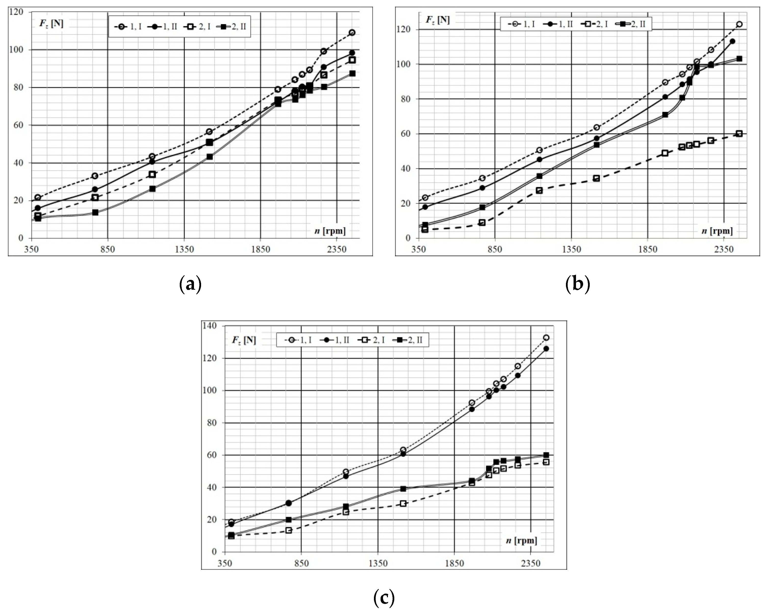
In addition, axial fan impeller was tested in two casing constructions. The first construction is a cylindrical casing, while the second one is profiled as a nozzle. Results for both models are presented and compared in
Figure 8. This design was tested for
βRa = 28°, 31° and 35°.
Angle
βRa variation leads to good thrust in normal, while to worse ones in reversible flow direction (
Figure 8). In all cases, the highest thrust values are reached for the highest fan rotation speed, what was expected. The smallest differences in thrust are achieved for
βRa = 35° and presented in
Figure 8c. This is obvious for the model 1 with cylindrical casing. The highest values of thrust are also achieved for this angle
βRa = 35°.
Influence of the flow direction in the reversible axial jet fan is more obvious for the second model with profiled nozzle. For this case significantly lower values of thrust are achieved for all angles
βRa. This is obvious for the highest presented angle
βRa = 35° (
Figure 8c). It could be concluded that this nozzle casing was not properly designed for the tested fan. Construction of model 2 resulted in a lower flow rate and thrust.
Analysis of sources of error and of uncertainty evaluation for the thrust measurement is provided for the one measurement point (n = 2266.8 rpm) which is close to the designed fan rotation speed (n = 2251 rpm). Calibration uncertainty of axial force (thrust) calibration, i.e., weights used for calibration, is ±0.54 g. Systematic uncertainty combines the uncertainty of transducer and calibration by the root-sum-square method and is ±0.075%. Random uncertainty of thrust measurements at 95% confidence level is 1.689 %, and total uncertainty of thrust measurement is 1.7%. This is in accordance with the used standard ISO 13350.


