Article

The Influence of Hydrodynamic Changes in a System with a Pitched Blade Turbine on Mixing Power

1
Faculty of Process and Environmental Engineering, Lodz University of Technology, Wolczanska 213, 90-924 Lodz, Poland
2
Faculty of Mechanical Engineering, Czech Technical University in Prague, Technicka 4, 166 04 Praha 6, Czech Republic
*
Author to whom correspondence should be addressed.
Processes 2021, 9(1), 68; https://doi.org/10.3390/pr9010068
Submission received: 14 December 2020 / Revised: 27 December 2020 / Accepted: 28 December 2020 / Published: 30 December 2020

Abstract

:
This paper presents an analysis of hydrodynamics in a tank with a 45° and 60° pitched blade turbine impeller operating while emptying the mixer and with an axial agitator working during axial pumping-down of water at different water levels above the impeller. Measurements made with the PIV method confirmed the change in direction of pumping liquid after the level dropped below the critical value, with an almost unchanged liquid stream flowing through the mixer. It was found that an increase in the value of the tangential velocity in the area of the impeller took place and the quantity of this increase depended on the angle of the blade pitch and the rotational frequency of the impeller. Change in this velocity component increased the mixing power.

1. Introduction

Batch production of suspensions in mechanically stirred tanks is often used in industrial practice [1,2]. The impeller is left running inside to prevent the solids from falling when emptying the tank. During tests on the suspension production process in a tank with a capacity of 300 m3, an increase in the need for mixing power was observed when emptying the tank shortly before the emergence of the impeller from the mixed liquid [3]. The observed increase in power is significant and can lead to engine overload and even damage. This phenomenon has not been described so far in classic monographs on mixing processes [4,5,6]. Only in the work of Paul et al. [7] is there mention of a significant increase in the forces acting on the agitator as the liquid surface passes through it. However, this has not been fully explained so far.
Detailed studies [8] only provide information on the possible increase in mixing power after activating the impeller while stirring the suspension, when the solid particles lifted from the bottom reach the stirrer level. This effect is most likely due to changes in the density of the slurry near the impeller.
In the course of our research on the phenomenon of an increase in mixing power when emptying the tank with a working pitched blade turbine (PBT) set to pump liquid downwards, it was established [9,10] that for a given geometric system, the higher the rotational frequency of the impeller, the lower the increase in mixing power as the liquid surface passes through the impeller. In the case of turbine-blade impellers, the influence of the blade inclination angle on the observed increase in mixing power was also noted. In this case, the greater the angle of inclination, the smaller the increase in power, and for the flat blade turbine (FBT) mixers no increase in power was observed at all. Thus, this phenomenon must be related to the hydrodynamics of the liquid in the mixer. Based on visual observations when emptying the mixer, changes were found in the liquid circulation in the tank. At the crucial moment—corresponding to a power surge—the PBT impeller stopped pumping liquid downwards. At the same time, it was found that the phenomenon of an abrupt increase in the mixing power does not occur when filling the tank. If the impeller rotates at a constant angular velocity, then the torque applied to it is transferred by blades to the liquid stream pumped by the stirrer and increases the momentum (angular momentum) of the liquid.

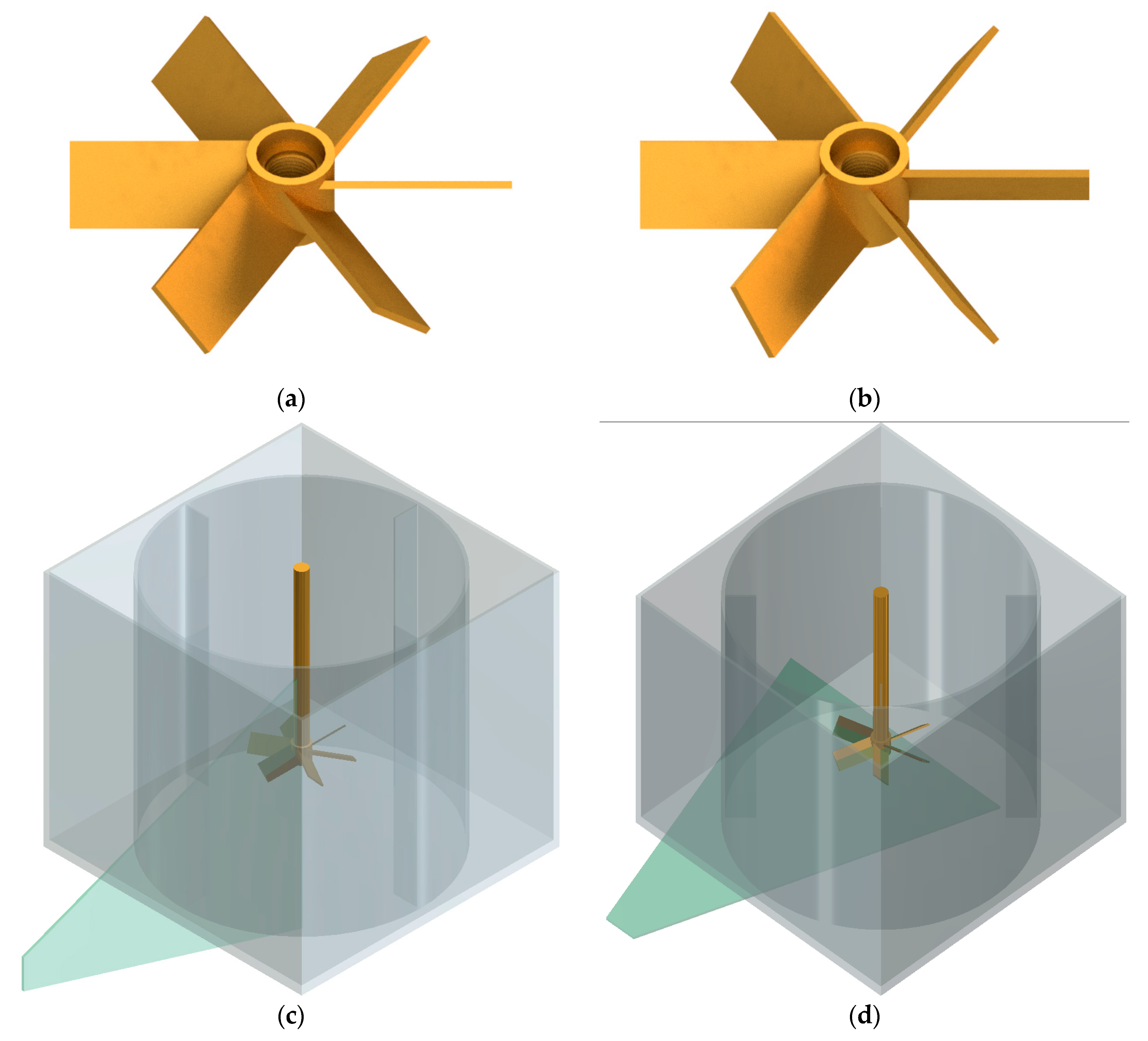
2. Materials and Methods

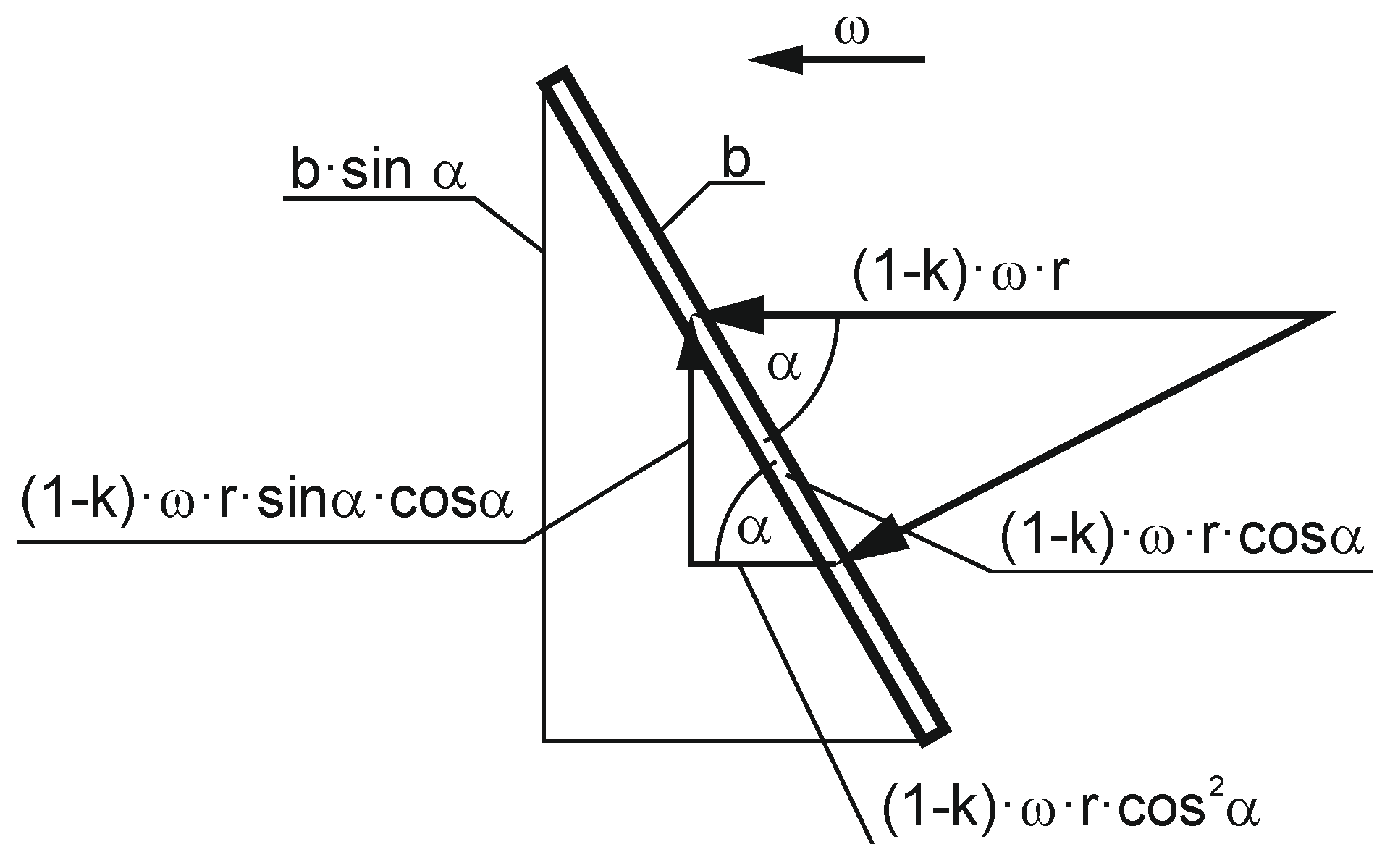
Theoretical Background

This can be described by the equation [11]:
M = ρ · V p · R m · C u
where: M—torque (Nm), ρ—liquid density (kg/m3), Vp—liquid stream flowing (m3/s), R m = D / 2 –impeller radius (m), D –impeller diameter (m), C u = k · U —tangential velocity component at the exit of the impeller (m/s), k—coefficient, U = π · N · D —tangential speed of the end of the stirrer blade (m/s). The above formula is true assuming that the liquid entering the agitator has no circumferential (tangential) component (i.e., it does not make a circular motion like at the inlet of a centrifugal pump [12,13]). This means that the momentum for this component can be neglected. The mixing power is determined based on the known relationship
P = M · ω = 2 · π · N · M
where: ω—angular velocity (rad/s), N—rotational frequency of the impeller (s−1). It is worth noting that the relationship (2) is universal and is applicable in the description and analysis of other unit processes, e.g., mixing of granular materials and granulation [14,15,16].
The liquid stream flowing through the impeller with blades inclined in relation to the plane z = const at the angle α = const (the angle does not vary along the radius r) can be estimated based on theoretical considerations. Figure 1 shows the components of the velocity vector in the radial and axial directions (b—the width of the shoulder blade, α—the angle of inclination of the blade relative to the plane of movement, U = ω·r –tangential speed of the blade).
The starting point for calculating the velocity components is the difference between the tangential speed of the blade and the tangential velocity of the liquid ( ω ω c ) · r = ( 1 k ) · ω · r , k, which acts as the tangential velocity on the paddle in the plane of stirrer motion z = const. This speed can be broken down into its components: radial ( 1 k ) · ω · r · c o s 2 α and axial ( 1 k ) · ω · r · sin α · cos a . Therefore, the radial flux for a cylindrical surface π · b · D for the condition ω · r = π · D · N is calculated as follows.
V p r = π 2 · ( 1 k ) · b · N · D 2 · cos 2 α
Axial flux for the cross-section π · D 2 / 4 is calculated by integration, taking the elementary section 2 · π · r · d r and lifting speed ω = 2 · π · N · r for specific radius. Hence:
V p z = ( 1 k ) · 2 · π · N · sin α · cos α · 2 · π · 0 D / 2 r 2 · d r
After integration you receive:
V p z = π 2 · ( 1 k ) · N · sin α · cos α · D 3 6
The relationships describing the pumping of liquids through axial impellers can also be found in other papers [17,18].
For normal operation of turbine mixers with inclined blades (H = D or H >> hm) it can be assumed that axial flow only occurs through the liquid and the radial flow is negligible (VpVpz, Vpr ≈ 0). However, it should be noted that Equation (5) also shows the dependence of the liquid stream flowing through the stirrer on the component of the peripheral velocity. Therefore, a dependence of the mixing power on this component in the area of the agitator should be expected. It is justified because the resistance force of the blades during their rotation in the liquid comes mainly from this component. This force can be calculated from these dependencies [19]:
F i = P · B i · s i n α z · ω · A
where: P—power used for mixing (W), ω—angular velocity of the impeller (rad/s), z—number of impeller blades, α—the angle of inclination of the blade relative to the horizontal, B i = h i 3 ( R i 3 r i 3 ) —for the rectangular i-th impeller element, A i = i = 0 n h i 4 ( R i 4 r i 4 ) —for all rectangular elements of the impeller blade. The aim of the work is to determine the effect of changes in the liquid flow in the mixer on the mixing power during emptying with the mixer working.
The tests were carried out in a flat-bottomed glass tank with a diameter of T = 292 mm, equipped with four baffles with a width of B = 0.1·T. A six-blade pitched blade turbine with diameter D = 100 mm and blade width b = 20 mm was placed at height hm = 100 mm (hmT/3) above the bottom of the tank. Impellers with a blade inclination angle were used, at 45° (PBT45—Figure 2a) and 60° (PBT6—Figure 2b). This type of axial impeller provides the shortest mixing times compared to other axial mixers, but with the highest mixing power [20,21,22,23]. The tank was filled with distilled water (t = 20 °C) up to H = 300 mm (HD). Medium diameter glass tracer particles of 10 μm were added to the water. In order to reduce optical distortions, the cylindrical tank was placed in a rectangular tank, and the space between the walls of the tanks was filled with water. Based on the analysis of the data on the mixing power, the speed measurements were limited to only two rotational frequencies of the impeller N = 90 min−1 (corresponding to the value of the number Froude F r = N 2 · D / g = 0.023 i and Reynolds number R e = N · D 2 · ρ / η = 15,000 ) and N = 240 min−1 (Fr = 0.163, Re = 40,000). The direction of rotation of the impeller was such that the axial flow of liquid generated by the impeller was directed to the bottom of the tank, as is usual when mixing suspensions.
The measurements were performed using the LaVision PIV Particle Image Velocimetry measurement system [24,25,26,27] with a two-pulse laser with a maximum power of 135 mW and an ImagePro camera with a resolution of 2048 px × 2048 px with a Nikkor 1.8/50 lens. The lens aperture was stopped down to the value ensuring the maximum resolving power (i.e., the aperture value was 5.6 [28]).
In order to determine the tangential and radial velocities, a 1 mm thick light knife was placed at the height of the stirrer. In the measurements of radial and axial velocities, the plane of the light knife was located about 2° in front of the baffle. A diagram showing the positions of the light knife is shown in Figure 2c,d. The measurement field was approximately 180 mm × 180 mm in the first case and approximately 190 mm × 190 mm in the second case. The laser frequency (pulses) was 2.7 Hz. Thus, for both configurations, the images were recorded for different positions of the blades with respect to the plane of symmetry between the baffles, although in the PIV method it is possible to synchronize the laser flashes with a specific position of the stirrer blade by using an external trigger [29] or selecting the frequency of the flashes [30].
Measurements were made for the height of the liquid in the tank equal to hw = 140 mm, 135 mm, 130 mm, 125 mm, 120 mm, 115 mm, 110 mm, and 105 mm. For each combination of rotational frequency and liquid height, 100 duplicates were taken to average the results. The proprietary DaVis 7.2 program was used for data processing. Two-pass data processing was used with the final size of the analyzed field 32 px × 32 px (i.e., approximately 2.8 mm × 2.8 mm) without overlapping.
In order to facilitate comparisons, dimensionless velocities were used in the further part of the work, i.e., the velocity of the liquid was divided by the peripheral velocity of the end of the impeller blade: U = π · D · N .

3. Results

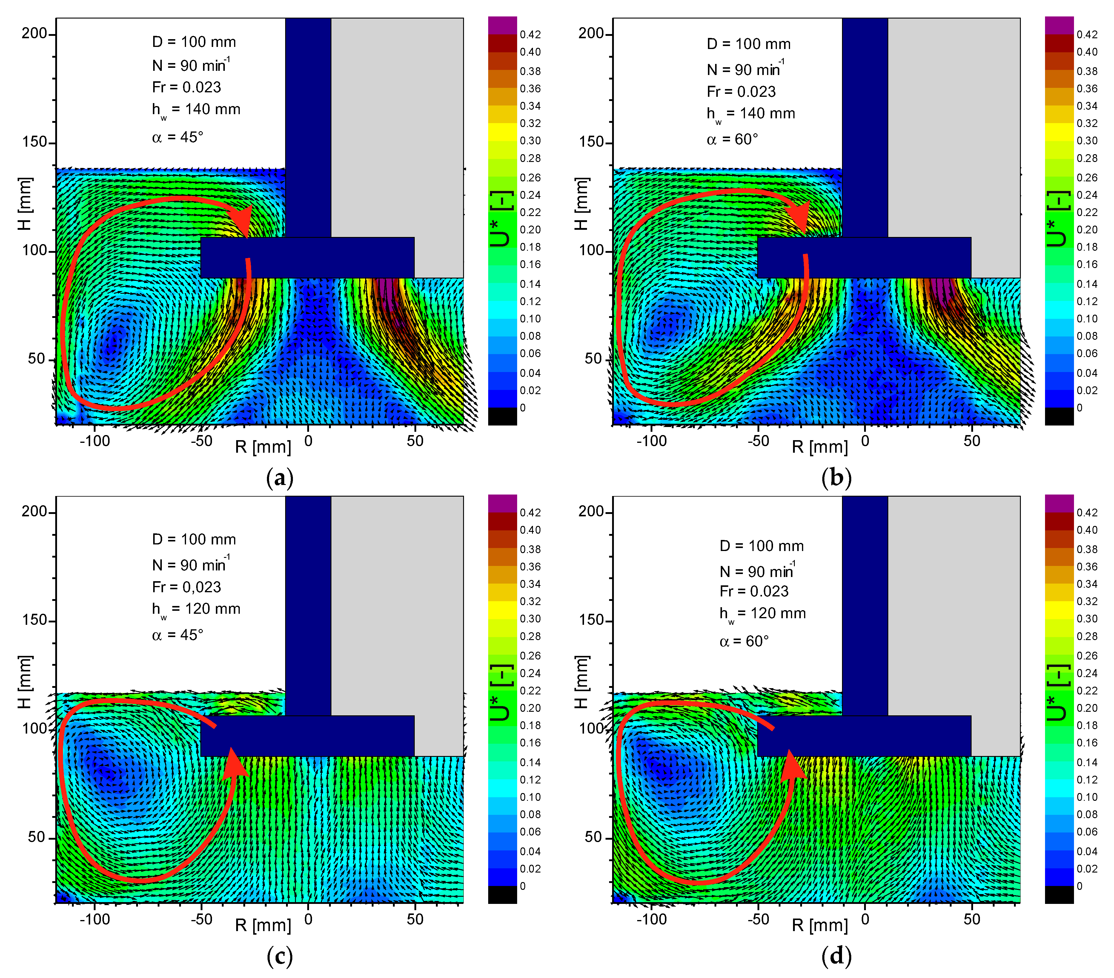
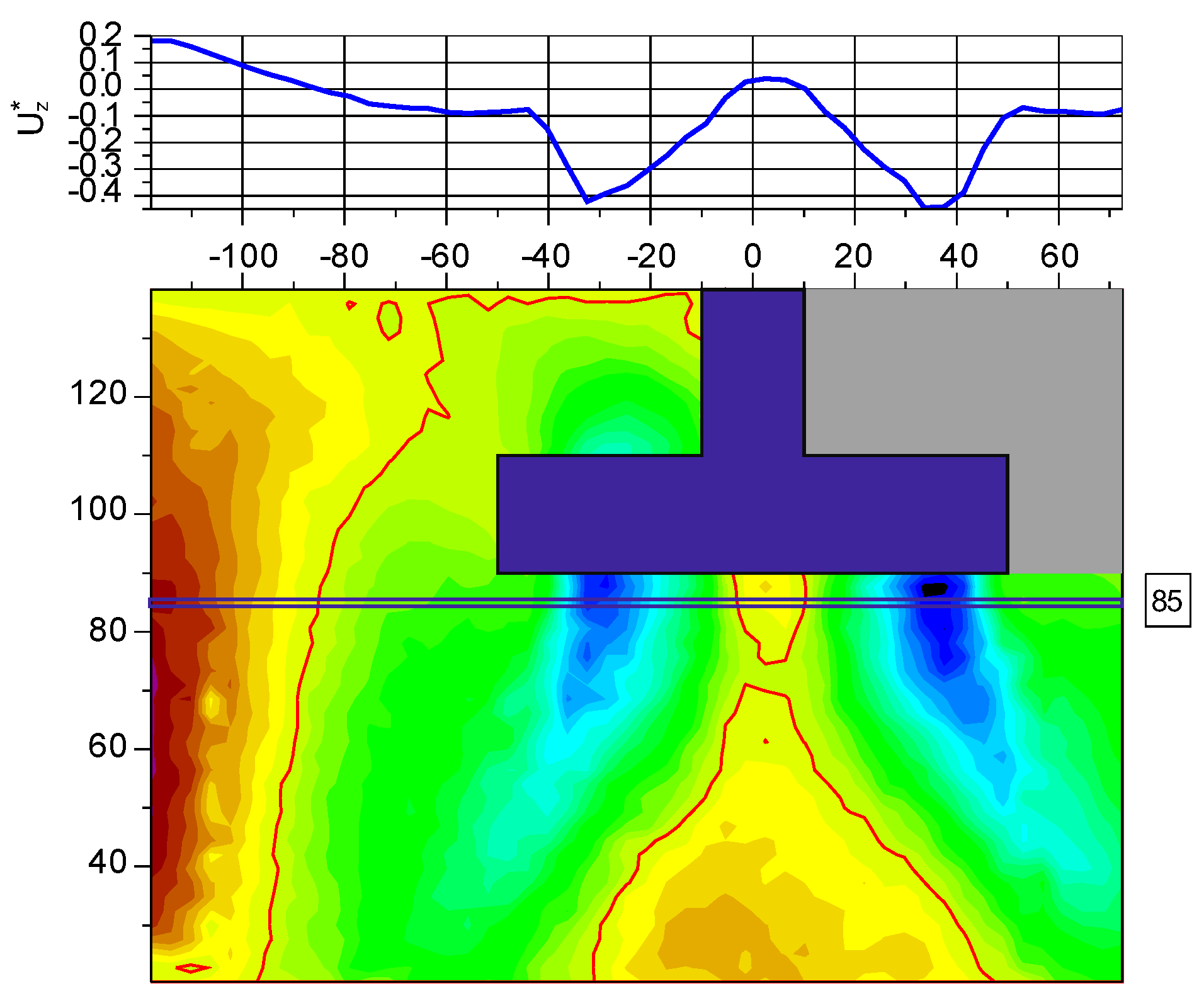
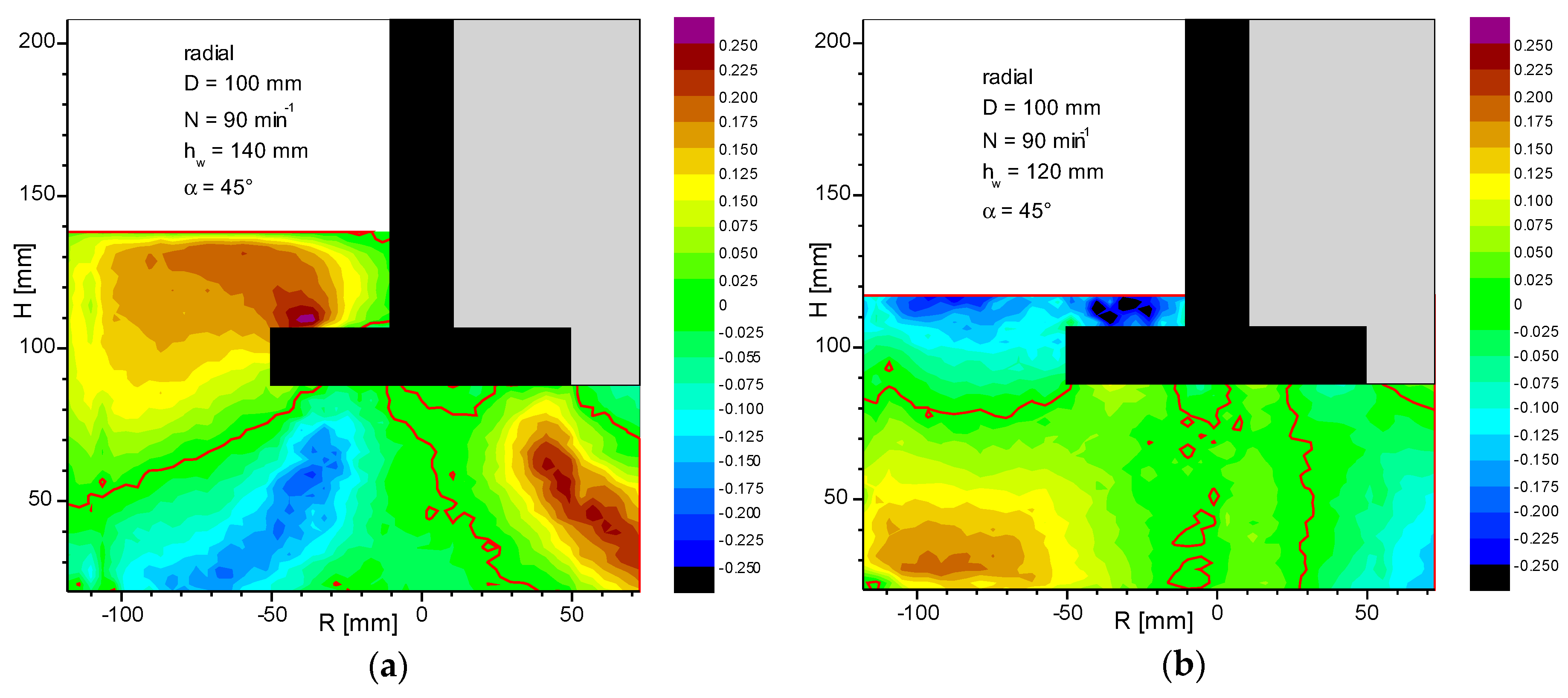
3.1. Changes in Fluid Circulation during Changes in the Height of the Liquid in the Tank

The liquid circulation method for PBT impellers is shown in Figure 3. At higher levels of liquid in the vessel, it is pumped down towards the bottom of the tank. After leaving the rotor, the liquid flows obliquely, so that centrally under the impeller there is a conical space in which the liquid flows upwards at a slow speed, with the apex angle of the cone being greater for a larger blade inclination angle (Figure 3a,b). The flow patterns obtained for large heights of liquid in the tank are consistent with the literature information [31,32,33,34,35,36]. After exceeding the critical height, the flow direction changes, the liquid under the impeller flows upwards and is radially directed over the impeller towards the tank wall, and the rising cone disappears (Figure 3c,d). From a height of h = 50 mm, the liquid flows practically in the axial direction, but with a uniform radial distribution. At the same time, the circulation core moves up to the level of the lower edge of the blades.
Analysis of Figure 3 shows that pumping of the liquid through the impeller only takes place in the axial direction, i.e., V p = V p z and, as assumed in the introduction, there is no radial discharge at the height of the stirrer. As Equation (1) shows, changes in mixing power should be correlated with changes in pumping efficiency. To specify numeric values Vp and Vpz, appropriate measurements of the distribution of axial and radial velocities were performed using the PIV system. After decomposing the velocity into the axial and radial components, the velocity profiles can be determined by interpolation in the program Origin, as shown in Figure 4. The obtained profiles agree with the literature information [37,38].
On the basis of the velocity profiles obtained, the pumping capacity was determined in MathCAD V p = i V z i · π · d i · c below the stirrer (h = 85 mm, di = 1, 3…99 mm, c = 2 mm) assuming the invariability of individual velocity components in the circumferential direction. The results obtained in the form of dimensionless pumping numbers K p = V p / ( N · D 3 ) are shown in Figure 5 and depend on the dimensionless parameter ( h w h d ) / T , in which hw—liquid level, h d = h m 0.5 · b · s i n α —distance of the bottom edge of the agitator from the bottom.
Lines (sections) connect the points between which the direction of the liquid flow through the impeller changes. After changing the pumping direction, no significant differences in the absolute values of the pumping numbers are observed. Moreover, when pumping upwards, in some cases the pumping capacity is even slightly reduced. This means that the mixing power should remain constant or it should decrease minimally when changing the pumping direction. Therefore, the source of the increase in mixing power should be sought in the behavior of the peripheral velocity component. The theoretical value of the pumping number can be determined by transforming the Equation (5).
K p = V p N · D 3 = π 2 6 · ( 1 k ) · sin α · cos α
For k = 0 i α = 45° we obtain Kp = 0.822, and for α = 60° Kp = 0.712 and similar values can be found in the literature [39]. The values obtained are greater than those measured, because in fact the peripheral velocity of the liquid is lower than the speed of the blade, i.e., k > 0. Even more value Kp = 1.167 dla h/T = 0.33 is obtained from the correlation given by Fořt [40] for mixers with a blade inclination angle α = 45°
K p = 0.947 · ( h T ) 0.19

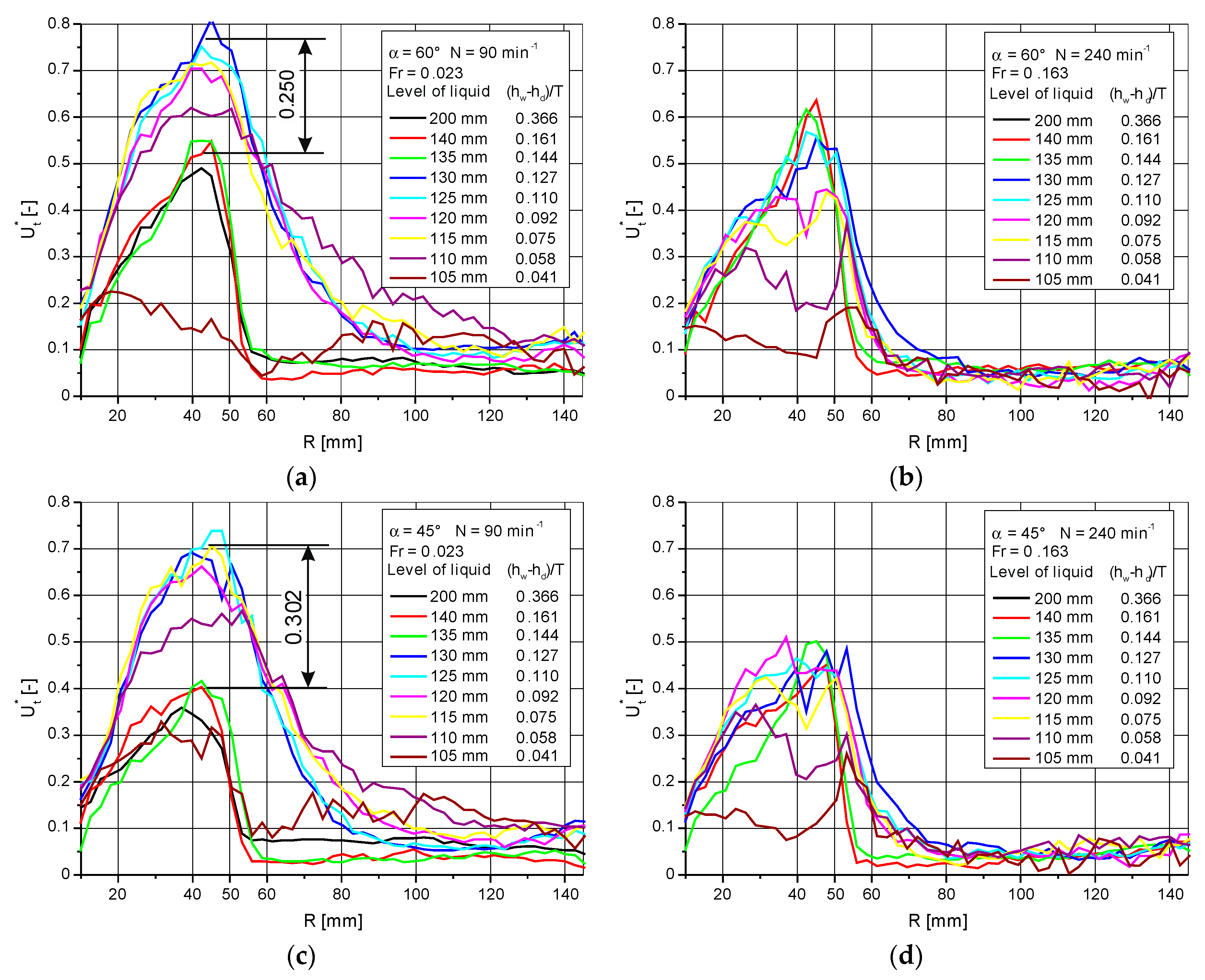
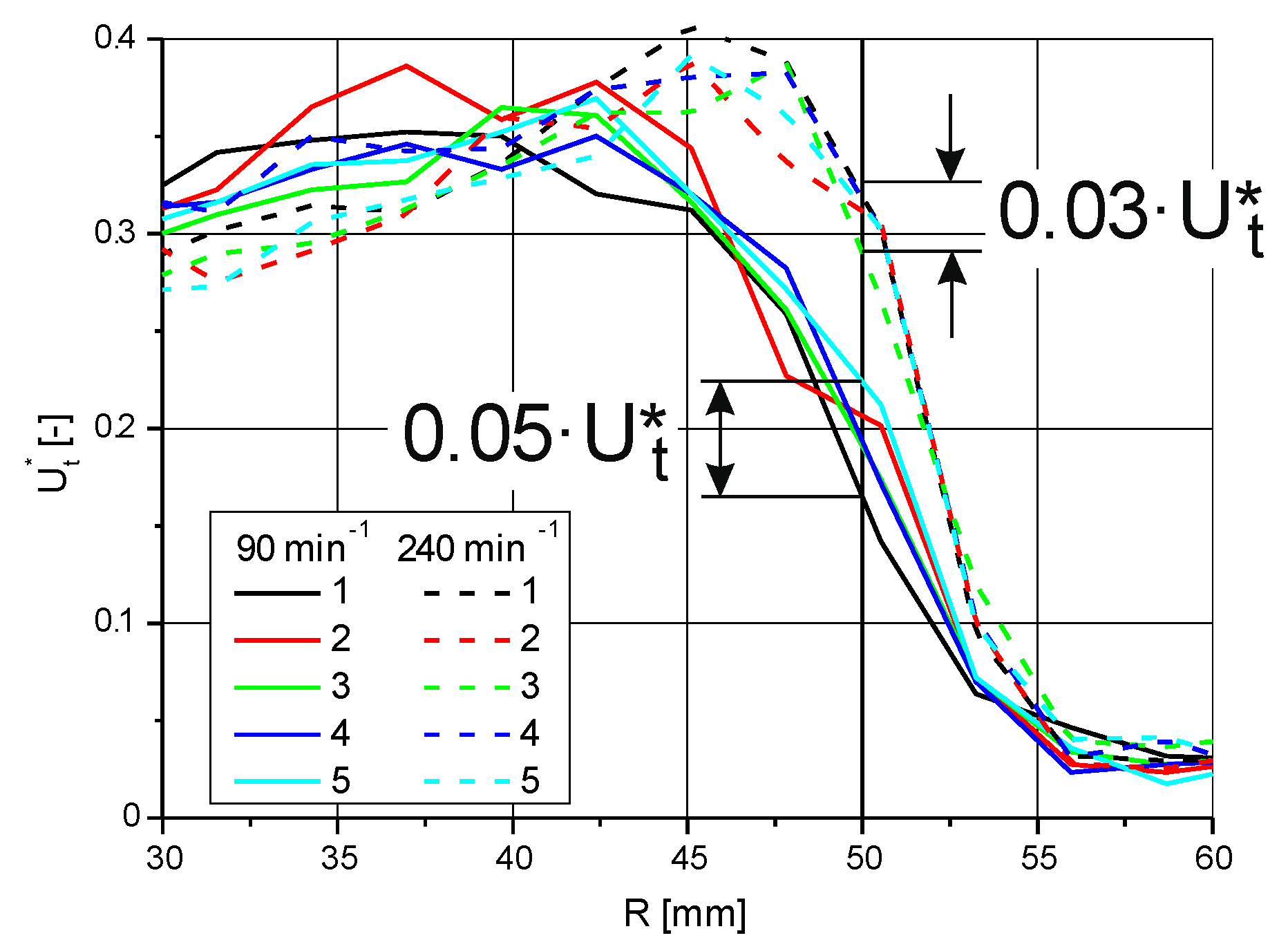
3.2. Tangential Velocity Profiles

Based on the data obtained from the PIV system, the tangential velocity profiles were determined in the program Origin at the height of the impeller in the plane of symmetry between the baffles. The results in the form of dimensionless velocities U t * are shown in Figure 6.
For the smallest of the analyzed rotational frequencies N = 90 min−1, an increase in velocity in the area of the impeller at the moment of changing the pumping direction is visible (marked in the figure). The greater difference occurs in the case of a smaller blade inclination angle α = 45°. Increasing the rotational frequency results in smaller speed variations when the fluid flow direction is changed.
The ratio of the maximum velocity values before and after the change of the circulation method is approximately 1.75 for the inclination angle α = 45° and 1.46 for α = 60°. These values are close to the multiplicity of the mixing power increase, 2 and 1.5 respectively. Thus, it can be assumed that the increase in mixing power is caused by the change in the peripheral speed of the liquid in the area of the impeller.

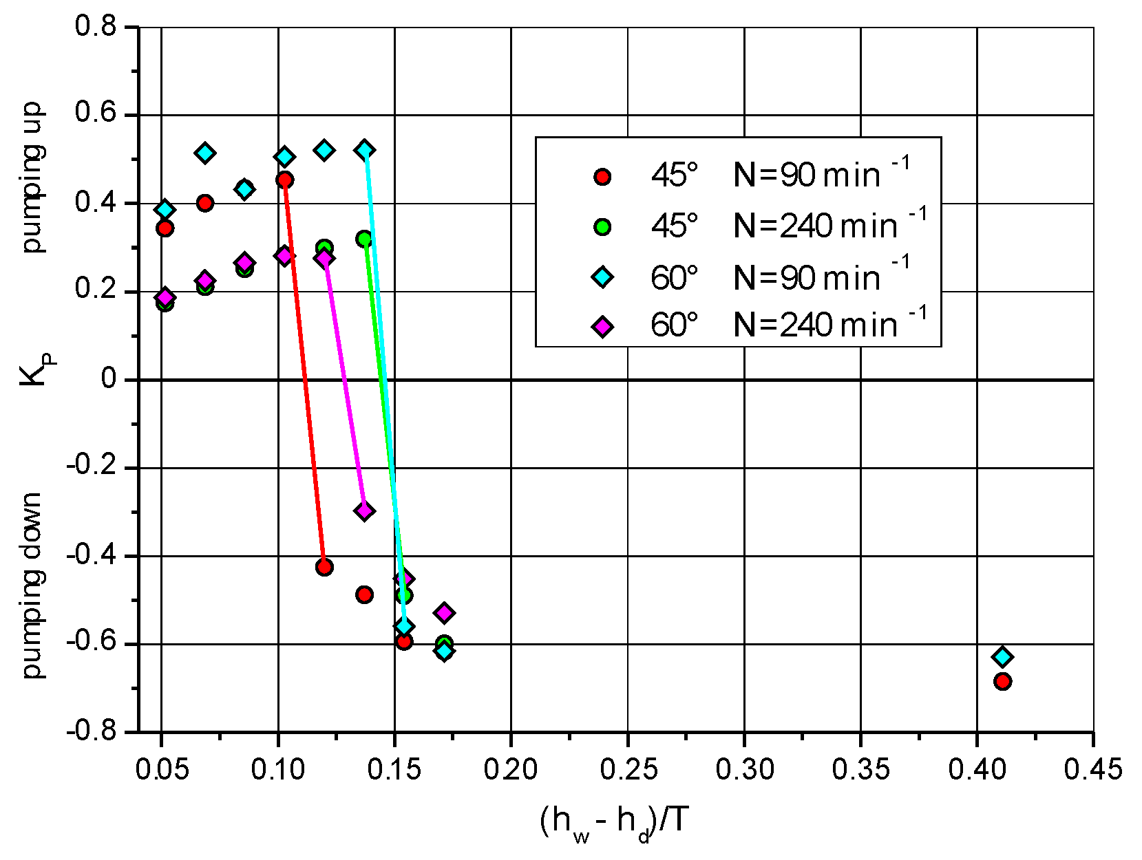
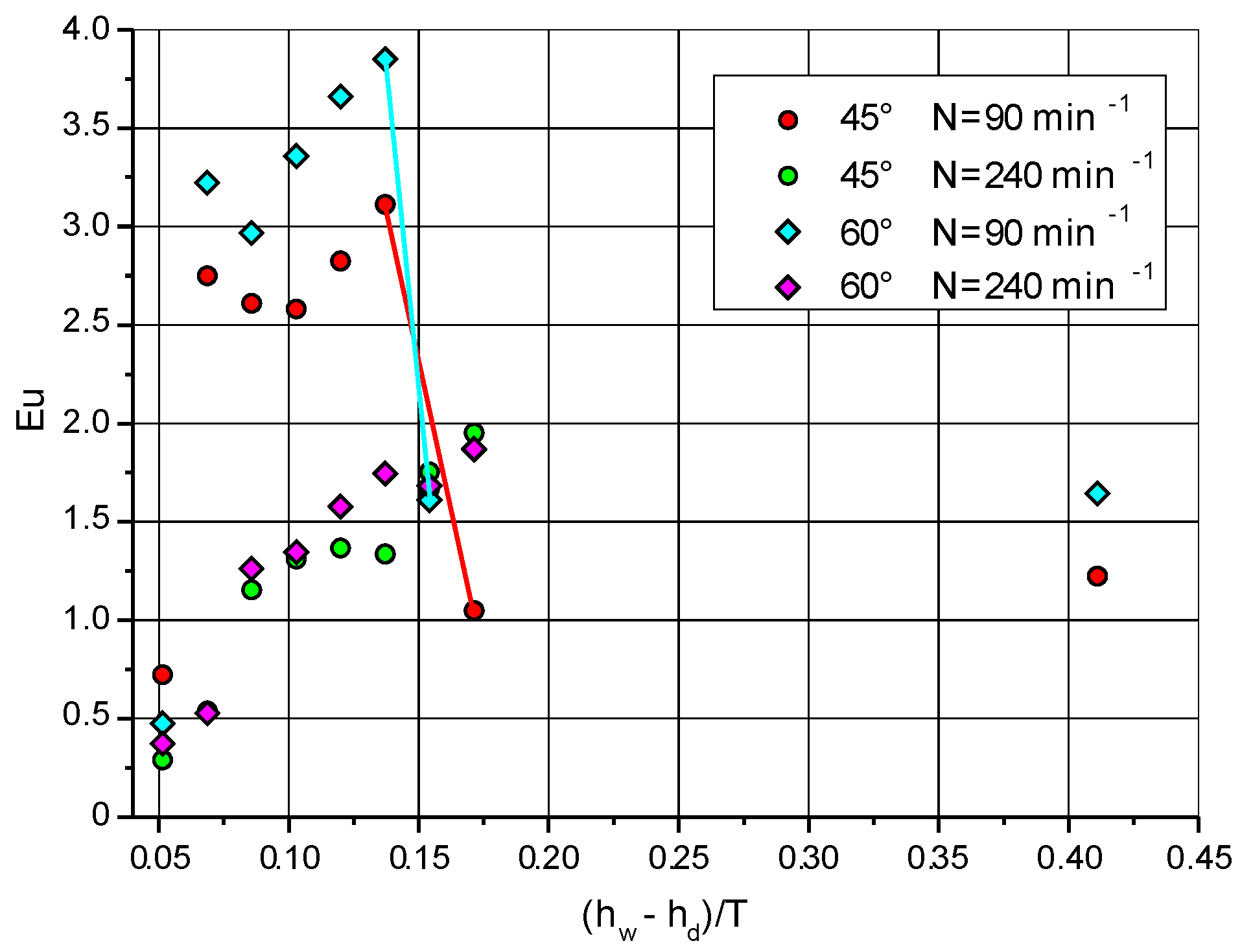
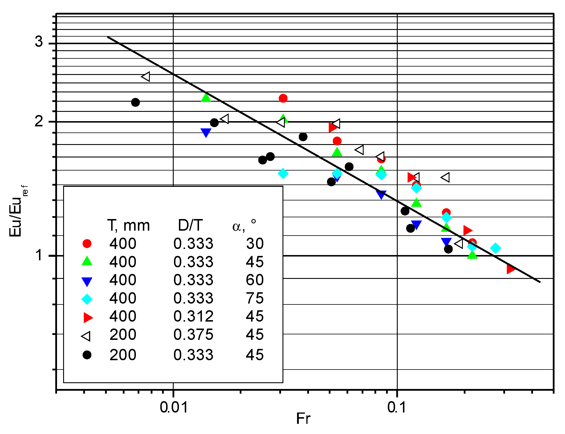
3.3. Estimating the Mixing Power

The relationship (1) presented at the beginning is less accurate than the direct measurement of the torque due to the need to experimentally determine the velocity of the liquid in the area of the impeller. Moreover, in the PIV method it is very difficult to estimate the measurement error, and the importance of this is evidenced by the information about new algorithms appearing in the literature [40,41,42]. Nevertheless, it should reflect the behavior of the system during hydrodynamic changes taking place in it. The results of calculating the power number using Equation (1) are shown in Figure 7, where the mixing power number is placed on the ordinate axis: E u = P o = P / ( N 3 · D 5 · ρ ) .
For pumping the liquid down (towards the bottom) at high liquid heights in the tank, low values of the mixing power were obtained. For the PBT45 impeller, direct measurements gave Eu = 1.53, and for the PBT60 impeller, Eu = 2.18. These results are consistent with the data in the literature [43,44]. The tangential velocity of the liquid at the outlet of the agitator has a great influence on the results obtained. For example, for the PBT45 impeller under the conditions of N = 90 min−1, hw = 140 mm, the measurements obtained the value of Eu = 1.05 for Cu = 0.09 m/s, but at a distance of R = 48.4 mm from the impeller axis the tangential velocity of the liquid is 0.132 m/s and the calculated power number value is Eu = 1.535. Unfortunately, it is practically impossible to determine the measurement error in the PIV method [45]. In addition, in asynchronous measurement, when the position of the blades in relation to the velocity profile determination line (plane) changes, the initial position of the blade may affect the results obtained. This is illustrated in Figure 8 showing the results of five consecutive measurements made to test this thesis. The differences in the values of the tangential velocity of the liquid for the radius of the stirrer Rm = 50 mm may reach about 0.05 of the velocity of the end of the stirrer blade. For the profiles from Figure 8, the values of the power numbers are obtained from Eu = 1.195 to Eu = 1.445 for N = 90 min−1 and from Eu = 1.888 to Eu = 2.145 for N = 240 min−1.
The multiplicity of the increase in mixing power is greater than the values obtained in direct measurements. Figure 7 shows that for blades set at an angle of 45° there should be a threefold increase, and for a 60° angle, a two-fold increase in power. In the measurements of torque for PBT45, a two-fold increase in power was achieved; for PBT60 this increase was 1.5 times, which can be read from Figure 9 presenting the results of previous studies [10]. These differences may result from incomplete fulfillment of the condition (assumption) that the liquid influencing the agitator impeller does not rotate.

4. Discussion

The results of the experiments presented in the paper allow for a preliminary hypothesis concerning the mechanism of increasing mixing power when emptying the mixers during the operation of the axial impeller while pumping the liquid down the tank [46]. The critical moment of the mechanism analyzed is undoubtedly the moment of changing the direction of the liquid flow through the impeller area, despite the unchanging parameters of the impeller itself. According to results from the analysis of the velocity distributions shown in Figure 3 for the liquid height in the tank hw = 140 mm, the liquid flows in the direction of liquid pumping through the rotating impeller (Figure 3a,b), and for hw = 120 mm the liquid flows through the area of the impeller in the opposite direction, i.e., to the bottom of the tank. This occurs when the liquid height above the upper edge of the impeller is approximately 10–15 mm. With high probability, it can be assumed that at this point the liquid layer above the impeller is so small that there is no possibility for secondary circulation lines, i.e., axial-radial circulation, to close within it. The rotating impeller starts to work like a radial-circumferential agitator (Figure 6). The impeller accumulates the liquid in front of the paddle, which increases the resistance to motion and increases the tangential velocity. At the same time, the stream of liquid ejected from the area of the impeller at a relatively high speed (Figure 9) begins to flow towards the bottom of the tank at the wall, thus changing the direction of circulation, which is shown in Figure 3c,d. It should be emphasized that this is a working hypothesis and a more extensive cycle of tests should be performed to confirm it. Figure 10 Radial represent the velocity maps: (a) hw = 140 mm; (b) hw = 120 mm.

5. Conclusions

Due to the incomplete fulfillment of the conditions, relationship (1) can be used to determine energy changes (mixing power) in a system with a mechanical impeller and a six-blade pitched blade turbine during hydrodynamic changes of the centrifugation of the liquid flowing into the impeller. Furthermore, this allows achievable accuracy of velocity measurements in the area of the impeller taking place when emptying the tank.
The increase in the mixing power when emptying the tank with the impeller working is determined by the abrupt increase in the tangential velocity component in the area of the impeller after changing the direction of liquid circulation. The increase in the value of the tangential velocity depends on the angle of the blades’ inclination and the rotational frequency of the impeller and is correlated with the changes in the mixing power when emptying the tank. As in the case of mixing power, smaller increments are observed for larger blade angles. Furthermore, increasing the rotational frequency (at the same angle of inclination) results in smaller increases in tangential velocity. In the paper, it is stated that it is practically impossible to determine the measurement error in the PIV method. According to Lehr and Boelcs [47] the standard measurement uncertainty of PIV velocity measurements for the mean velocity field is less than 4%, and in the regions of strong velocity gradients it is smaller than 5% when the test-section is quasi-two-dimensional and the out-of-plane components of the vectors cause only minor errors.

Author Contributions

Conceptualization, J.S. and C.K.; methodology, J.S., C.K., S.S., T.J., and F.R.; validation, J.S., C.K., S.S., T.J., and F.R.; formal analysis, J.S., C.K., S.S., T.J., and F.R.; investigation, J.S., C.K., S.S., T.J., and F.R.; resources, J.S., C.K., S.S., T.J., and F.R.; data curation, J.S., C.K., S.S., T.J., and F.R.; writing—original draft, J.S., C.K., S.S., T.J., and F.R.; writing—review and editing, J.S., C.K., S.S.; visualization, J.S., C.K., S.S., T.J., and F.R.; supervision, J.S., C.K., S.S., T.J., and F.R.; project administration, J.S., C.K., S.S., T.J., and F.R.; funding acquisition, J.S., C.K., S.S., T.J., and F.R. All authors have read and agreed to the published version of the manuscript.

Funding

This research was funded by Ministry of Education, Youth and Sports of the Czech Republic: OP RDE CZ.02.1.01/0.0/0.0/16_019/0000753.

Institutional Review Board Statement

Not applicable.

Informed Consent Statement

Not applicable.

Data Availability Statement

Not applicable.

Acknowledgments

The work was created as part of the statutory activity of the Department of Chemical Engineering of Lodz University of Technology and the grant OP RDE CZ.02.1.01/0.0/0.0/16_019/0000753 financed by the Ministry of Education, Youth and Sports of the Czech Republic.

Conflicts of Interest

The authors declare no conflict of interest.

References

  1. Rieger, F.; Jirout, T.; Rzyski, E. Mixing of suspensions. Selection of the mixer and tank. Inż. Ap. Chem. 2002, 41, 111–112. (In Polish) [Google Scholar]
  2. Grenville, R.K.; Mak, A.T.C.; Brown, D.A.R. Suspension of solid particles in vessels agitated by axial flow impellers. Chem. Eng. Res. Des. 2015, 100, 282–291. [Google Scholar] [CrossRef]
  3. Mazoch, J.; Rieger, F.; Jirout, T. Report TH 01020879; TECHMIX: Brno, Czech Republic, 2016. (In Czech) [Google Scholar]
  4. Uhl, V.W.; Gray, J.B. Mixing. Theory and Practice; Academic Press: London, UK, 1973; pp. 112–176. [Google Scholar]
  5. Nagata, S. Mixing: Principles and Applications; John Wiley & Sons: New York, NY, USA, 1975; pp. 62–65. [Google Scholar]
  6. Zlokarnik, M. Stirring. Theory and Practice; Wiley-VCH: Weinheim, Germany, 2001; pp. 76–96. [Google Scholar]
  7. Paul, E.L.; Atiemo-Obeng, V.A.; Kresta, S.M. Handbook of Industrial Mixing; John Wiley & Sons: Hoboken, NJ, USA, 2004; pp. 543–584. [Google Scholar]
  8. Mak, A.T.C. Solid-Liquid Mixing in Mechanically Agitated Vessels. Ph.D. Thesis, University College, London, UK, 1992. [Google Scholar]
  9. Rieger, F.; Jirout, T.; Moravec, J.; Stelmach, J.; Kuncewicz, C.Z. The phenomenon of increased mixing power consumption during tank emptying. Przemysł Chemiczny 2019, 98, 962–966. (In Polish) [Google Scholar]
  10. Stelmach, J.; Kuncewicz, C.Z.; Rieger, F.; Moravec, J.; Jirout, T. Increase of mixing power during emptying of tanks with turbine-blade impellers. Przemysł Chemiczny 2020, 99, 239–243. (In Polish) [Google Scholar]
  11. Стренк, Ф. Перемешивание и Аппараты с Мешалками; Химия: Leningrad, Russia, 1975; pp. 111–117. (In Rusian) [Google Scholar]
  12. Perry, R.H. Section 10 Transport and storage of fluids, 10–24 Centrifugal pump. In Perry’s Chemical Engineers Handbook, 7th ed.; McGraw-Hill: New York, NY, USA, 1997. [Google Scholar]
  13. Introduction to Hydraulic Pumps. Available online: https://www.engineeringclicks.com/hydraulic-pumps/ (accessed on 12 December 2020).
  14. Heim, A.; Gluba, T.; Obraniak, A. The effect of the wetting droplets size on power consumption during drum granulation. Granul. Matter 2004, 6, 137–143. [Google Scholar] [CrossRef]
  15. Heim, A.; Kaźmierczak, R.; Obraniak, A. Model of granular bed dynamics in the disk granulator: Model dynamiki złoża ziarnistego w granulatorze talerzowym. Chem. Proc. Eng. 2004, 25, 993–998. (In Polish) [Google Scholar]
  16. Obraniak, A.; Gluba, T. Model of energy consumption in the range of nucleation and granule growth in drum granulation bentonite. Physicochem. Probl. Miner. Process. 2012, 48, 121–128. [Google Scholar]
  17. Fort, I.; Seichter, P.; Pes, L. Axial thrust of axial flow impellers. Chem. Eng. Res. Des. 2013, 91, 789–794. [Google Scholar] [CrossRef]
  18. Chapple, D.; Kresta, S.M.; Wall, A.; Afacan, A. The effect of impeller and tank geometry on power number for a pitched blade turbine. Trans. IChemE 2002, 80, 364–372. [Google Scholar] [CrossRef]
  19. Kozulin, N.A.; Sokołow, W.N.; Szapiro, A.J. Maszyny Przemysłu Chemicznego. Przykłady i Zadania; WNT: Warszawa, Poland, 1976; pp. 32–38. (In Polish) [Google Scholar]
  20. Fořt, I.; Jirout, T. A study on blending characteristics of axial flow impellers. Chem. Proc. Eng. 2011, 32, 311–319. [Google Scholar] [CrossRef] [Green Version]
  21. Jirout, T.; Rieger, F. Impeller design for mixing of suspensions. Chem. Eng. Res. Des. 2011, 89, 1144–1151. [Google Scholar] [CrossRef]
  22. Amira, B.B.; Driss, Z.; Karray, S.; Abid, M.S. PIV Study of the Down-Pitched Blade Turbine Hydrodynamic Structure. In Proceedings of the Fifth International Conference on Design and Modeling of Mechanical Systems, Djerba, Tunisia, 25–27 March 2013; pp. 237–244. [Google Scholar]
  23. Amira, B.B.; Driss, Z.; Abid, M.S. Experimental Study of the 60° PBT6 Pitching Blade Effect with a PIV Application. In Proceedings of the Multiphysics Modelling and Simulation for Systems Design Conference, Sousse, Tunisia, 17–19 December 2014; pp. 91–100. [Google Scholar]
  24. Raffel, M.; Willert, C.; Werseley, S.; Kompenhans, J. Particle Image Velocimetry, 2nd ed.; Springer: Berlin/Heidelberg, Germany, 2007; pp. 15–122. [Google Scholar]
  25. Brossard, C.; Monnier, J.C.; Barricau, P.; Vandernoot, F.X.; Le Sant, Y.; Champagnat, F.; Le Besnerais, G. Principles and Applications of Particle Image Velocimetry. Available online: https://hal.archives-ouvertes.fr/hal-01180587/document (accessed on 12 December 2020).
  26. Bastiaans, R.J.M. Cross-correlation PIV.; Theory, Implementation and Accuracy. Available online: https://www.researchgate.net/publication/241849539_Cross-correlation_PIV_theory_implementation_and_accuracy (accessed on 12 December 2020).
  27. 2D & Stereo PIV. Available online: https://www.lavision.de/en/applications/fluid-mechanics/2d-stereo-piv/index.php (accessed on 12 December 2020).
  28. Available online: https://www.optyczne.pl/66.4-Test_obiektywu-Nikon_Nikkor_AF_50_mm_f_1.8D_Rozdzielczo%C5%9B%C4%87_obrazu.html (accessed on 2 July 2020).
  29. Ranade, V.V.; Perrard, M.; Le sauze, N.; Xuereb, C.; Bertrand, J. Trailing vortices of Rushton turbine: PIV Measurements and CFD sSimulations with snapshot approach. Trans. IChemE 2001, 79, 3–12. [Google Scholar] [CrossRef]
  30. Heim, A.; Stelmach, J. The comparison of velocities at the self-aspirating disk impeller level. Przemysł Chem. 2011, 90, 1642–1646. (In Polish) [Google Scholar]
  31. Khopkar, A.R.; Mavros, P.; Ranade, V.V.; Bertrand, J. Simulation of flow generated by an axial-flow impeller. Batch and Continuous Operation. Chem. Eng. Res. Des. 2004, 82, 737–751. [Google Scholar] [CrossRef] [Green Version]
  32. Aubin, J.; Mavros, P.; Fletcher, D.F.; Bertrand, J.; Xuereb, C. Effect of axial agitator configuration (up-pumping, down-pumping, reverse rotation)on flow patterns generated in stirred vessels. Trans. IChemE 2001, 79, 845–856. [Google Scholar] [CrossRef] [Green Version]
  33. Jaworski, Z.; Dyster, K.N.; Nienow, A.W. The effect of size, location and pumping direction of pitched blade turbine impellers on flow patterns: LDA Measurements and CFD Predictions. Trans IChemE 2001, 79, 887–894. [Google Scholar] [CrossRef]
  34. Mavros, P.; Xuereb, C.; Fořt, I.; Bertrand, J. Investigation by laser Doppler velocimetry of the effects of liquid (flow rates and feed positions on the flow patterns induced in a stirred tank by an axial-flow impeller. Chem. Eng. Sci. 2002, 57, 3939–3952. [Google Scholar] [CrossRef] [Green Version]
  35. Ge, C.-Y.; Wang, J.-J.; Gu, X.-P.; Feng, L.-F. CFD simulation and PIV measurement of the flow field generated by modified pitched blade turbine impellers. Chem. Eng. Res. Des. 2014, 92, 1027–1036. [Google Scholar] [CrossRef]
  36. Schafer, M.; Yianneskis, M.; Wachter, P.; Durst, F. Trailing Vortices around a 45° Pitched-Blade Impeller. AIChE J. 1998, 44, 1233–1246. [Google Scholar] [CrossRef]
  37. Sahu, A.K.; Kumar, P.; Joshi, J.B. Simulation of flow in stirred vessel with axial flow impeller: Zonal modeling and optimization of parameters. Ind. Eng. Chem. Res. 1998, 37, 2116–2130. [Google Scholar] [CrossRef]
  38. Ozcan-Taskin, G.; Wei, H. The effect of impeller-to-tank diameter ratio on draw down of solids. Chem. Eng. Sci. 2003, 58, 2011–2022. [Google Scholar] [CrossRef]
  39. Tsui, Y.-Y.; Chou, J.-R.; Hu, Y.-C. Blade angle effects on the flow in a tank agitated by the pitched-blade turbine. J. Fluids Eng. 2006, 128, 774–782. [Google Scholar] [CrossRef]
  40. Fořt, I.; Sedláková, V. Pumping effect of high-speed rotary mixers. Collect. Czechoslov. Chem. Commun. 1967, 33, 836–849. [Google Scholar] [CrossRef]
  41. Lecordier, B.; Trinite, M. Advanced PIV Algorithms with Image Distortion Validation and Comparison Using Synthetic Images of Turbulent Flow. Available online: https://www.researchgate.net/publication/228862071_Advanced_PIV_algorithms_with_Image_Distortion_Validation_and_Comparison_using_Synthetic_Images_of_Turbulent_Flow (accessed on 12 December 2020).
  42. Stanislas, M.; Okamoto, K.; Kahler, C.J.; Westerweel, J. Main results of the Second International PIV Challenge. Exp. Fluids 2005, 39, 170–191. [Google Scholar] [CrossRef]
  43. Major-Godlewska, M.; Karcz, J. Power consumption for an agitated vessel equipped with pitched blade turbine and short baffles. Chem. Pap. 2018, 72, 1081. [Google Scholar] [CrossRef] [PubMed] [Green Version]
  44. Pietranski, J.F. Mechanical Agitator Power Requirements for Liquid Batches. Available online: https://www.google.pl/url?sa=t&rct=j&q=&esrc=s&source=web&cd=&cad=rja&uact=8&ved=2ahUKEwiA6e_ys8PtAhUPxosKHTPsA0sQFjAAegQIBRAC&url=https%3A%2F%2Fwww.researchgate.net%2Fprofile%2FPrem_Baboo%2Fpost%2FWhat_is_the_required_power_of_submerged_mixer_in_equalization_tank_before_ABR%2Fattachment%2F59d626b379197b8077984f89%2FAS%253A322848827084802%25401453984566839%2Fdownload%2Fk103content.pdf&usg=AOvVaw2oZkJL_36DSIXTg0wsemod (accessed on 12 December 2020).
  45. Adrian, Ł.; Piersa, P.; Szufa, S.; Romanowska-Duda, Z.; Grzesik, M.; Cebula, A.; Kowalczyk, S.; Ratajczyk-Szufa, J. Experimental research and thermographic analysis of heat transfer processes in a heat pipe heat exchanger utilizing as a working fluid R134A. In Renewable Energy Sources: Engineering, Technology, Innovation; Springer Proceedings in Energy ICORES 2017; Mudryk, K., Werle, S., Eds.; Springer: Berlin/Heidelberg, Germany, 2018; pp. 413–421. ISBN 978-3-319-72370-9. [Google Scholar] [CrossRef]
  46. Dzikuć, M.; Kuryło, P.; Dudziak, R.; Szufa, S.; Dzikuć, M.; Godzisz, K. Selected Aspects of Combustion Optimization of Coal in Power Plants. Energies 2020, 13, 2208. [Google Scholar] [CrossRef]
  47. Lehr, A.; Bölcs, A. Application of a particle image velocimetry system to the investigation of unsteady transonic flows in turbomachinery. In Proceedings of the 9th International Symposium on Unsteady Aerodynamics, Aeroacoustics and Aeroelasticity of Turbomachines, Lyon, France, 4–8 September 2000; Ferrand, P., Aubert, S., Eds.; Springer: Berlin/Heidelberg, Germany, 2000. [Google Scholar]
Figure 1. Distribution of velocity vectors for an inclined blade.
Processes 09 00068 g001
Figure 2. Tested impellers (a) PBT45, (b) PBT60 and the position of the light knife during the measurements, (c) vertical: measurement of radial and axial components, (d) horizontal: measurement of tangential and radial components.
Processes 09 00068 g002
Figure 3. Liquid flow before the partition for the PBT45 and PBT60 impellers: (a) hw = 140 mm, α = 45°; (b) hw = 140 mm, α = 60°; (c) hw = 120 mm, α = 45°; (d) hw = 120 mm, α = 60°.
Processes 09 00068 g003
Figure 4. Map and profile of axial velocity at a height of h = 85 mm above the bottom for hw = 140 mm and N = 90 min−1 (PBT45 impeller).
Processes 09 00068 g004
Figure 5. Pumping capacity depending on the height of the liquid in the tank.
Processes 09 00068 g005
Figure 6. Tangential velocity profiles at the height of the impeller hm. (a) N = 90 min−1, α = 60°; (b) N = 240 min−1, α = 60°; (c) N = 90 min−1, α = 45°; (d) N = 240 min−1, α = 45°.
Processes 09 00068 g006
Figure 7. The power number calculated using Equation (1).
Processes 09 00068 g007
Figure 8. Profiles for five consecutive measurements (PBT45, hw = 140 mm).
Processes 09 00068 g008
Figure 9. Increase in mixing power when emptying the tank for various sizes of impellers.
Processes 09 00068 g009
Figure 10. Radial velocity maps: (a) hw = 140 mm; (b) hw = 120 mm.
Processes 09 00068 g010
Publisher’s Note: MDPI stays neutral with regard to jurisdictional claims in published maps and institutional affiliations.

