Article

Numerical and Experimental Study on Waviness Mechanical Seal of Reactor Coolant Pump

1
School of Energy Science and Engineering, Harbin Institute of Technology, Harbin 150001, China
2
Harbin Electric Power Equipment Co. Ltd., Harbin 150066, China
3
Sino-French Institute of Nuclear Engineering and Technology, Sun Yat-Sen University, Zhuhai 519082, China
*
Author to whom correspondence should be addressed.
Processes 2020, 8(12), 1611; https://doi.org/10.3390/pr8121611
Submission received: 10 October 2020 / Revised: 3 December 2020 / Accepted: 4 December 2020 / Published: 7 December 2020

Abstract

:
Based on the fluid hydrodynamic lubrication theory, a mathematical model of liquid film lubrication was established for the waviness hydrodynamic mechanical seal of a reactor coolant pump. The influences of the waviness amplitude and pressure on the sealing performance were investigated by the numerical simulation. The numerical results showed that the leakage rate increases linearly as the pressure and waviness amplitude increase under the force balance condition. The minimum liquid film thickness decreases first and then increase as the pressure increases. Stationary slide rings with three different waviness amplitudes were processed using the pre-deformation method and tested at different pressure and temperature. The experiments showed that all the three kinds of seal have good stability under different pressure conditions. The experimental results showed that the leakage rate is influenced by the pressure, waviness amplitude, and temperature, and the leakage rate increases as the pressure increases. The comparison between experimental and numerical results showed that both the temperature and pressure affect the seal performance, and tends to a smaller leakage rate, which is quite different from the numerical values. Therefore, the multi-physics coupling effect should be considered in the numerical analysis of seal performance, and this will be studied in the further works.

1. Introduction

The reactor coolant pump (RCP) is one of the most critical pieces of primary equipment in a nuclear power plant, and the only rotating equipment in the nuclear island which suffers both high temperature and pressure [1]. The RCP’s shaft seal consists of three stages identical hydrodynamic mechanical seals in series to prevent the leakage of primary medium from the outside of the RCP. The mechanical seal is designed to operate normally under 17.3 MPa for 10 h. Compared with the ordinary mechanical seals, the hydrodynamic mechanical seal realizes the non-contact between the sealing surfaces by using the closing force caused by the hydrodynamic effect between the sealing end faces, with a variety of grooves on the sealing surface. This characteristic greatly reduces the wear of the sealing surface and improves the reliability and lifespan [2,3]. Two types of mechanical seal are always used in the shaft-sealed RCP, including the waviness end face [4,5,6] mechanical seal and ordinary mechanical seal [7,8], where the former has a longer lifespan due to its hydrodynamic characteristics. Due to its excellent hydrodynamic effect and good controlled leakage ability, the waviness end face has been widely applied in the field of the RCP. By utilizing the hydrodynamic effect, the waviness mechanical seal can form a micro-scale thin layer of fluid film between the end faces, which avoids the direct contact between the seal pairs, reduces the wear and prolongs the life [9]. Because of these outstanding advantages, many studies on the waviness end face mechanical seal have been made [10,11,12,13,14]. The wavy tilt dam (WTD) as one type of the waviness surface was studied by many researchers. The concept of WTD was first proposed by Lebeck and Young [15] who suggest that the hydrostatic and hydrodynamic effects are produced by the radial taper and the circumferential waviness of the end face, respectively, which leads to sufficient opening force and liquid film stiffness, and is suitable for high-parameter conditions. The stability researches of WTD mechanical seal are mainly focus on several aspects. Etsion et al. [13] established a closed analytical solution for the mechanical seal model to study the lubricating film pressure and the axial separating force, whereby the face geometry is combined with waviness and coning. To improve the leakage rate control, Salant et al. [16] simulated the hydraulically controlled RCP’s seal under different deformations and geometries of the end face by changing the pressure in the cavity of non-rotating seal ring. In addition to the independent hydrodynamic research, some coupling simulations were also applied to analyze the coupled thermo-hydrodynamic characteristics. To study the 3D detailed behavior of the WTD mechanical seal, based on the Reynolds equation [17,18], Liu et al. [14,19,20,21] simulated and analyzed the WTD seal based on the three-dimensional thermal elastic hydrodynamic model, and the results showed that the sealing mechanism was the combined effect of hydrodynamic and hydrostatic. The film cavitation occurs at the high velocity region, and the hydrostatic effect prevailed at the high-pressure region. Djamaï et al. [22] established a numerical model of thermo-hydrodynamic mechanical face seals based on the coupling Reynolds equation and energy equation to analyze the influence of operating and design parameters. Brunetière et al. [23] analyzed the influence of the design and operating parameters on the thermo-hydrodynamic behavior of the mechanical end face seals in steady and dynamic tracking modes. To research the influence factors of cavitation starting and evolution, Li et al. [24] analyzed the effects of different waviness amplitudes, numbers and tapers on the cavitation characteristics. The results indicated that the start and evolution of the cavitation were affected by both the waviness and radial taper, and the change of the cavitation region along the circumferential direction was influenced by the waviness, while that along the radial direction depended on the taper.
As for the manufacture of the waviness groove on the sealing end face, the normal processing methods used mainly include the milling, electric spark processing, grinding and etc. Huo et al. [25,26,27] proposed a three-axis, ultra-precision grinding method using line contact kinematics for machining the WTD seal rings, which can achieve high form accuracy and low surface roughness of the waviness end faces. Han [28] researched the super precision milling process for the waviness end face of the tungsten carbide seal ring. The surface roughness could reach about 7 nm. Wang [29] used the electric spark processing method to pre-machine the waviness end face of the static ring. However, this work should be improved. On one hand, this method has suffers from a long processing time and serious carbon deposits, and on the other hand, the surface roughness cannot meet the requirements of less than 0.4 μm. Recently, Feng et al. [30] proposed a new grinding method through extrusion deformation of the seal ring. The extrusion deformation tooling and metal gaskets were used to deform the sealing ring into a waviness shape. After grinding, the required waviness shape was formed. The experimental results showed that the seal completely satisfies the requirements of nuclear power plant, while it can obtain high accuracy surface roughness and high reliability. In short, as for the field of waviness end face mechanical seal research, the main focus is on the predicting sealing performance by using theoretical models and cavitation characteristics, which are relatively rare in experimental research. The forming of the waviness end face limited to the equipment conditions and process methods is only focused on the research method of the contractible scale model. The leakage of reference work for the research of the prototype leads to a disconnection between the theoretical research and the experimental results.
In view of the above problems, this work, based on the Reynolds equation of liquid film lubrication, combined with the actual processing waviness end face, establishes a liquid film lubrication mathematical model of the mechanical seal which can represent waviness groove. The influences of waviness amplitude, temperature and pressure on the leakage rate of the mechanical seal systematically were studied by comparing the numerical results with experimental results. Moreover, it obtains the difference between theoretical analysis and experimental research, which provides a reference for the parameter optimization design of the seal end face and the coupling study of multiple physical fields.

2. Numerical Analysis

The mechanical seal of RCP mainly consists of stationary base ring (SBR), rotating slide ring (RSR), stationary slide ring (SSR) and rotating base ring (RBR), as shown in Figure 1a. The structure of SSR is as in Figure 1b.

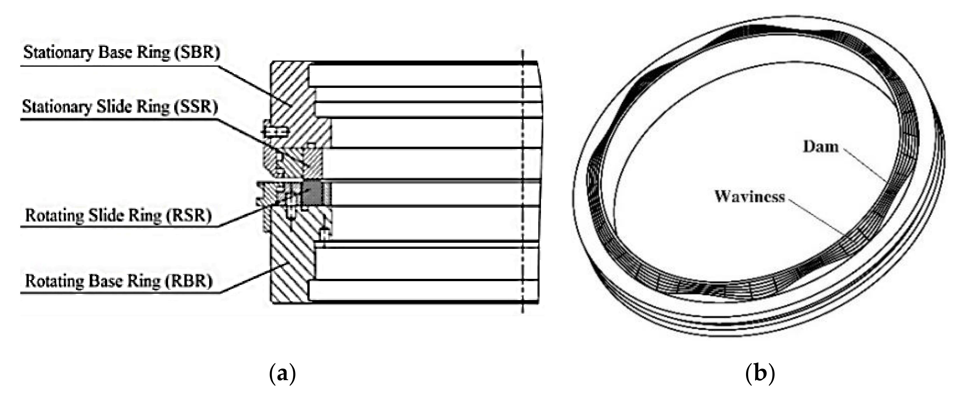
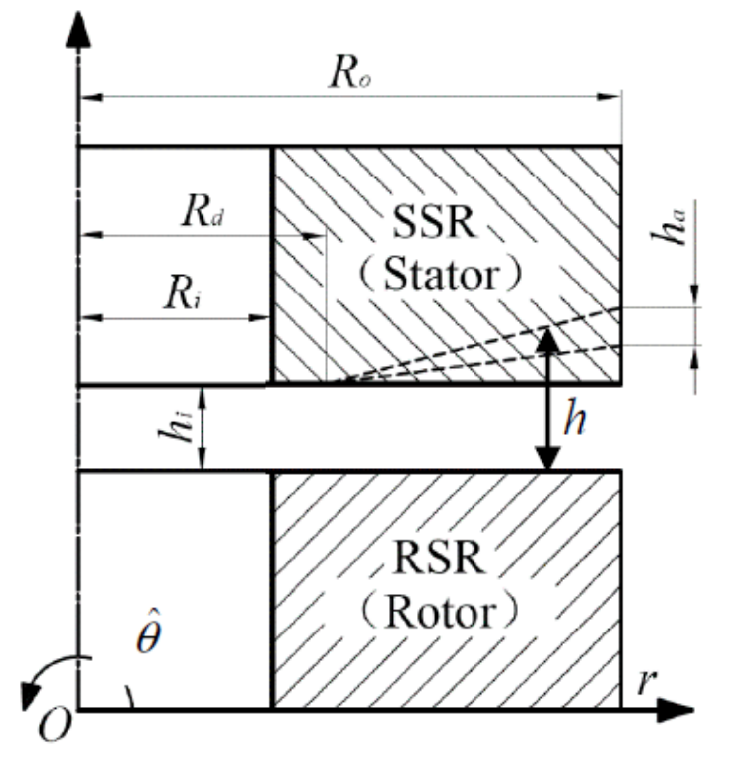
2.1. Geometric Model

The geometric model is composed of rotating slide ring (RSR) and stationary slide ring (SSR), as shown in Figure 2. The lubrication film lies between rotating slide ring and stationary slide ring. Rotating slide ring has an ideal plane on the sealing end face. A uniform circumferential waviness lies on the end face of the stationary slide ring, and a flat dam lies at the inner diameter. The thickness of the liquid film at any position can be expressed as follows:
h ( r , θ ^ ) = h i , R i r R d h i + r R d R o R d h a ( 1 cos z × θ ^ ) , R d r R o
where the inner and outer radius of the sealing end face are Ri and Ro, respectively, the dam radius of the sealing end face is Rd, the minimum distance between rotating slide ring and stationary slide ring is hi, and the waviness amplitude is ha. θ ^ is the coordinates of the rotating direction.

2.2. Mathematical Model

In order to establish the mathematical model, the following basic assumptions are listed:
  • The lubrication film between is the Newtonian fluid, and the flow is laminar flow. Since the working fluid of the mechanical seal is always the water, the assumption of Newtonian fluid is reasonable, and since the velocity of working fluid is small enough, the assumption of laminar flow also is reasonable.
  • The heat generation of the viscous shear is ignored, and the liquid film viscosity is considered to be constant. Since the heat generation of the viscous shear is very low and the temperature of the liquid film is basically constant, this assumption is reasonable.
  • The pressure variation along the direction of the film thickness is not considered. This is the basic assumption of Reynolds equation.
The governing equation of the lubrication film in rectangular coordinates can be expressed by the steady-state Reynolds equation considering cavitation of the liquid film, and the expression is expressed as follows:
x ( h 3 12 μ p x ) + y ( h 3 12 μ p y ) = 1 2 U x ( θ h ) x + 1 2 U y ( θ h ) y
where μ is the dynamic viscosity, which is defined as:
μ = μ 0 e β T T 0
where μ0 is the dynamic viscosity under the reference temperature T0; T is the local temperature of the fluid film and β is the viscosity-temperature coefficient; p is the pressure; Ux and Uy are the shear velocity in the x and y directions; θ is the ratio of the density of the liquid film during cavitation to that in the liquid state, and when the flow is in full liquid film, θ = 1. When 0 < θ < 1, the flow is in cavitation state.
In order to solve Equation (2), two kinds of boundary conditions need to be added, among which the JFO cavitation boundary conditions for liquid film cavitation is defined as follows:
p = p c , 0 < θ < 1         in   non-cavitation   zone p > p c ,                 θ = 1         in   cavitation   zone
The pressure boundary condition is defined as follows:
p = p i r = R i p = p o r = R o
In Equations (4) and (5), pc is the cavitation pressure of the liquid film and is set to 0 MPa in this work because of the large sealing pressure. Pressure pi and po are respectively the medium pressure at the inner and outer radius of the sealing end face.
The governing equation is calculated using the finite element method (FEM) due to its complication. The convection-diffusion Equation (2) will be convective dominant when the speed of the sealing ring is large, which will lead to numerical oscillation of Galerkin FEM. Therefore, the streamline upwind/Petrov–Galerkin (SUPG) technology described in reference [31] is used to solve the lubrication Equation (2), and the relevant sealing performance parameters could be calculated after obtaining the liquid film pressure. In order to obtain the sealing performance in the force balance state of the stationary slide ring, the axial force balance equation is solved by using dichotomy method to obtain the minimum film thickness. The axial force balance equation is written as:
F o = G + F s
where Fo is the axial opening force, G is the gravity of static ring, and Fs is the downward spring force.
The triangular mesh configuration is used in this simulation, and a perturbation term is added to the weight function in the streamline direction, which can suppress the diffusion perpendicular to the flow direction in advance and overcome the false diffusion problem of the upwind discretization. The weak integral form of lubrication control Equation (2) can be written as:
Ω h 3 6 μ w x p x + w y p y d Ω Ω w U θ h x + V θ h y + 1 2 τ S U P G U w x + V w y U θ h x + V θ h y d Ω = 0
where w is the weight function and Ω is the calculation domain and τSUPG is the coefficient of stability. By defining the FEM variables as: w = wiNi, p = piNi, θ = θiNi with N being the interpolation function of element, the Equation (7) can be rewritten as:
K i j p p j K i j θ θ j = 0
K i j p = Ω h 3 6 μ N i x N j x + N i y N j y d Ω K i j θ = Ω h N i U N j x + V N j y d Ω Ω 1 2 τ S U P G h U N i x + V N i y U h N j x + V h N j y d Ω
To solve Equation (8), the switch function F is introduced, and the unknown variable p and θ can be expressed using the general variable Φ as:
Φ = F p + 1 F θ
For the liquid film intact area, F = 1 and Φ = p, while for the cavitation area, F = 0 and Φ = θ. Substituting Equation (9) into Equation (7), one obtains:
A i j Φ j = K i j θ F j
where
A i j = K i j p C i j K i j θ I i j C i j
with I being the unit matrix; C is a matrix whose other areas are 0 except for the same value as F on the diagonal. After obtaining the film pressure p, the sealing performance parameters such as liquid film bearing capacity, leakage rate and friction coefficient can be calculated.
Since the static seal ring is in floating state, the thickness of the lubricating oil film is determined by the balance between the bearing capacity of the lubricating liquid film and the gravity of the static seal ring, spring force and the static pressure of the sealing medium. Therefore, the balance film thickness of the liquid film needs to be obtained by solving the force balance equation of the static seal ring as:
p d Ω F c = 0
where Fc is the closing force of the static ring, which is the summation of the gravity G of the static ring, the spring force Fs, and the hydrostatic pressure in the sealed cavity.

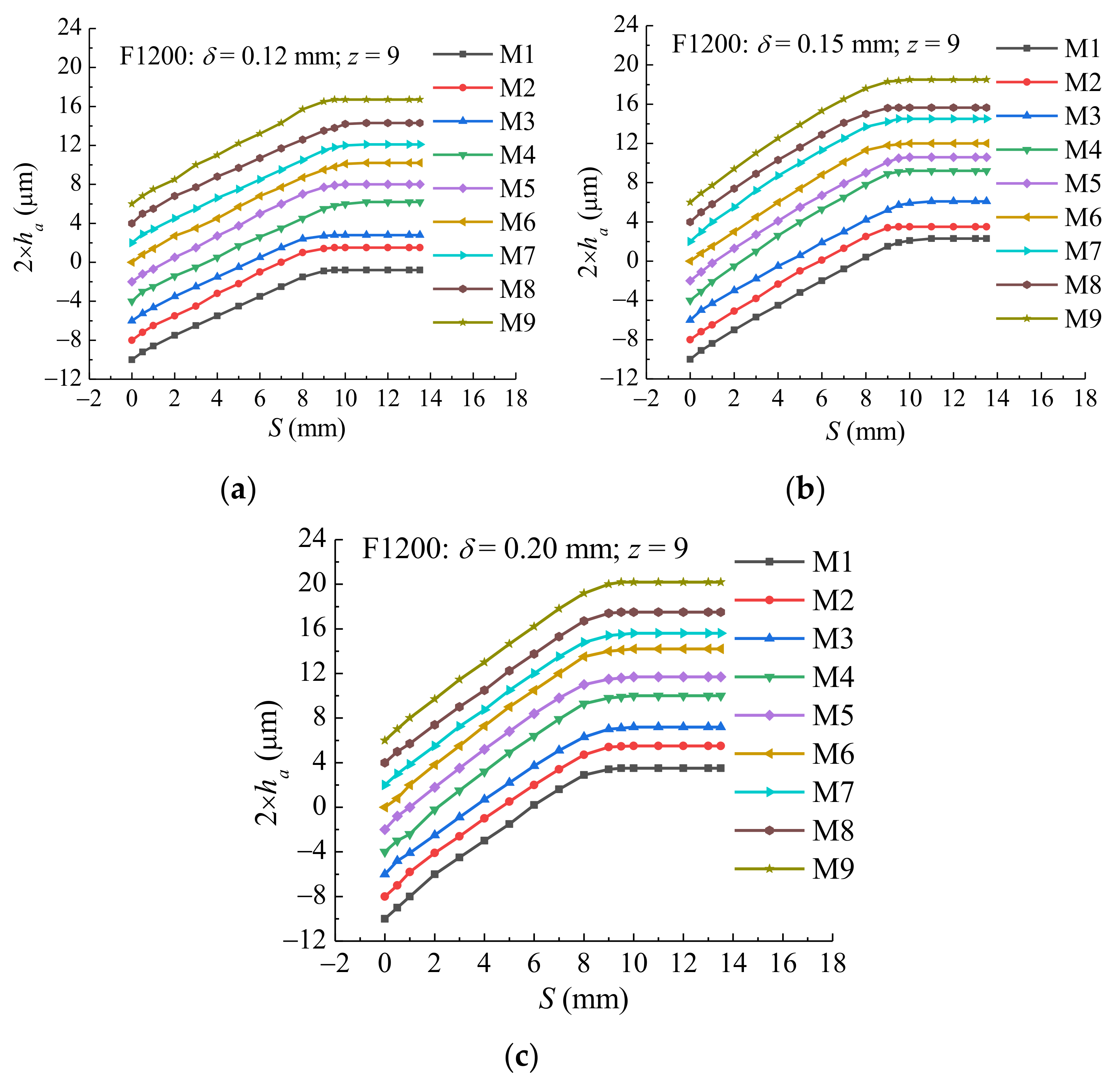
2.3. Calculating Results and Analysis

Table 1 shows the geometric and operating parameters used in this work and the materials of the friction pair are carbon and tungsten carbide (WC). Except for special instructions, all the parameters taken in this work are shown in Table 1. The listed waviness amplitude is the actual measured value of the end face of the stationary slide ring manufactured, and is corresponds to Section 2. The simulating parameters are the same as the experimental parameters.
In Figure 3, it shows the variation law of the minimum liquid film thickness hi and the leakage rate Q with the pressure in balance state. As can be seen from Figure 3a, the minimum liquid thickness decreases first and then increases with the increase of pressure, which is consistent with the research results in literature [5], which is due to the cavitation of the lubrication film under the small film thickness that leads to the enhancement of the hydrodynamic effect of the liquid film. Under the same pressure, the larger waviness amplitude leads to higher minimum liquid film thickness. The hydrostatic effect of the liquid film increases with the waviness amplitude increases. As can be seen from Figure 3b, the leakage rate increases approximately linearly with the increase of the pressure, and the larger waviness amplitude leads to larger leakage rate. Moreover, the upward trend of the leakage rate curve is more obvious.

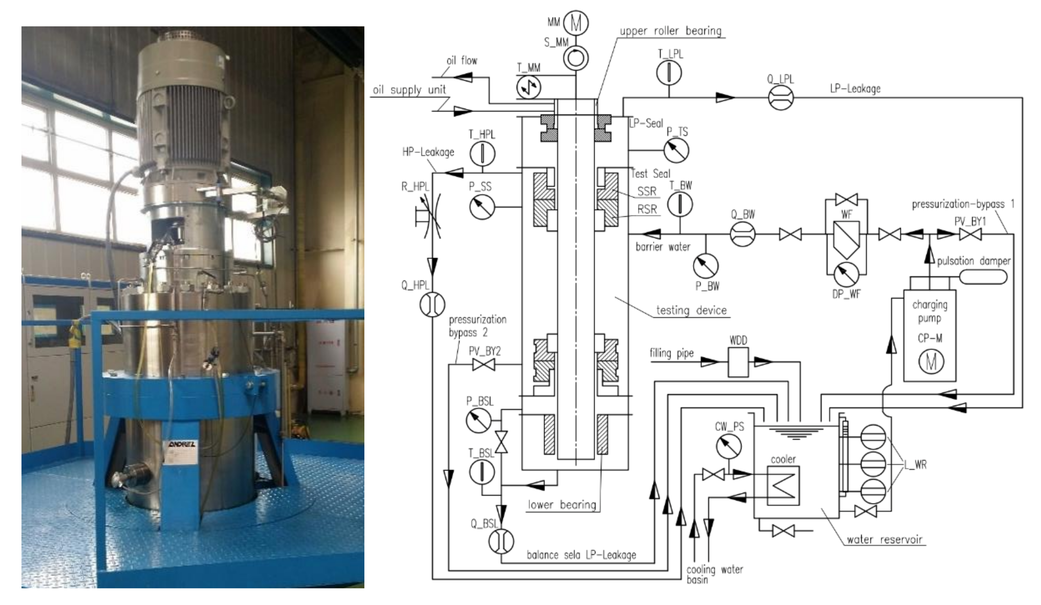
3. Experimental Research

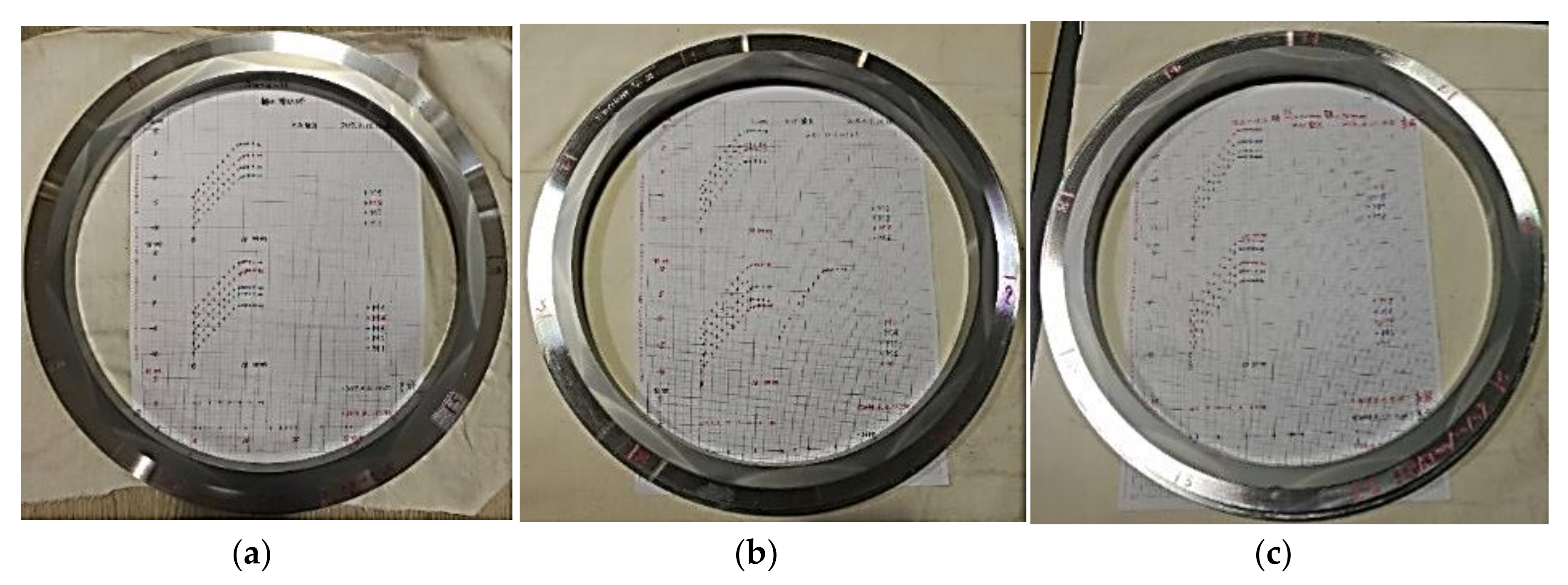
3.1. Manufacture and Experiment of the Sealing Rings

According to the method and process described in literature [17], three kinds of the morphologies with different waviness amplitude on seal end face of the stationary slide rings are ground by using the metal gaskets with different thickness (δ = 0.12 mm, 0.15 mm and 0.20 mm). In order to make the surface roughness of the sealing end face satisfy the requirement, the grinding powder F1200 named boron carbide (B4C) is used for grinding. Its particle size is 1–7 μm and Vickers hardness is 31 GPa. The final roughness of the sealing end face of the stationary slide ring is about 0.0572 μm. The three stationary slide rings are shown in Figure 4.
Each wave groove of the static ring is divided equally in the radial direction, and the detection is recorded by moving slowly from the outer circle of the static ring along the inner circle. The nine waves are measured in nine groups, namely: M1–M9. The 9 waves of each static ring are made of the same metal gasket by compression deformation, which can ensure the same wave amplitude, and the single wave is also the same. The central section of each waviness is used as the measurement section of the waviness amplitude. The height of the waviness is measured and recorded by sliding from the outside to the inside of the sealing end face of the stationary slide ring to obtain the waviness amplitude ha. It can be seen from the Figure 5 that the processed waviness has good variation consistency. According to Equation (1), the waviness amplitude ha of the corresponding metal gasket thickness of 0.12 mm, 0.15 mm, and 0.20 mm is about 5.0 μm, 6.3 μm, and 6.9 μm, respectively.

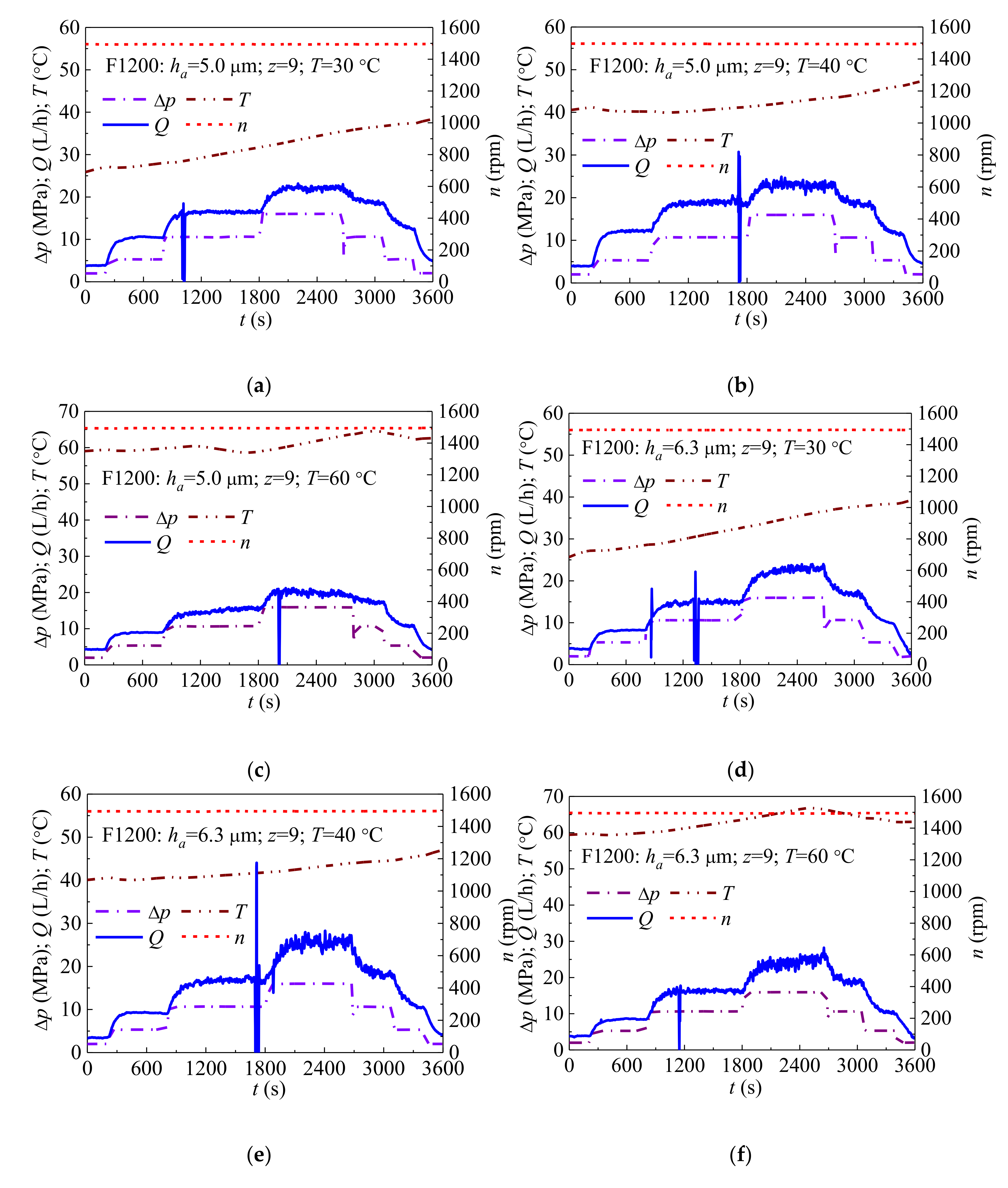
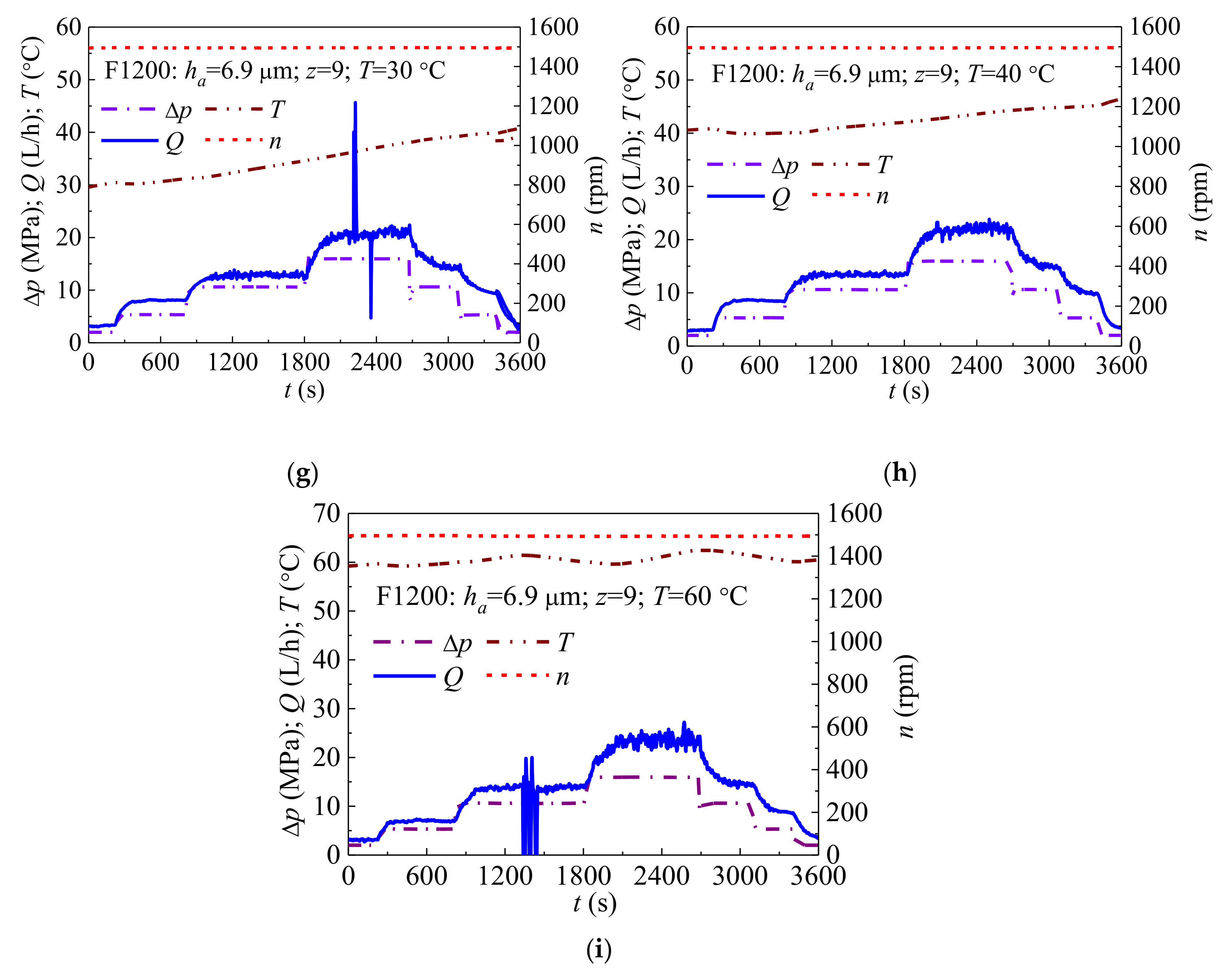
3.2. Performance Test

Figure 6 shows the test rig, which consists of the testing device, motor, oil supply unit, charge pump, water reservoir, water deionization system, cooling water cycle, PLC cabinet, DAQ cabinet, cooling water basin, and other components. The test medium is purified tap water (6–8 pH, conductivity ≤ 20 μS/cm) which supplied by the water deionization system and stored in the water reservoir. The high-pressure charge pump supplies the testing device with pressurized barrier water, which is necessary for test rig operation, and is fed directly from the water reservoir. The process water returns from the testing device to the water reservoir via multiple leakage water pipes. The oil supply unit ensures the necessary lubrication of the upper roller bearing of the testing device, and the lower bearing of the testing device is a medium lubricated hydrodynamic bearing. A cooling water basin supplies the water for the cooling pump and should be situated outside of the test bench room. The constant temperature of the water from the cooling water basin ensures the thermal stability of the testing device. The operation and control of the test rig are regulated and controlled by the PLC unit in the PLC cabinet. The DAQ switching cabinet contains components necessary to collect, record and display data during a test run. The measurement point data collected by the measuring instrument (see Table 2) are fed back to the DAQ unit.
As for the above three kinds of waviness sealing end faces, the measurement of the leakage rate under different temperature and pressure are performed. During the test, the speed of the shaft is 1485 rpm, the pressure is gradually increased to the highest and then decreased (the pressures are 2.0 MPa, 5.3 MPa, 10.6 MPa, and 15.9 MPa respectively). The medium temperature in the sealing chamber and leakage rate of the low-pressure side are recorded in per second. In order to consider the different working pressure, the pressure increase and decrease is applied via three steps. Beginning with about 2.0 MPa, the pressure is increased to 5.3 MPa rapidly (representing normal operation of a 3-stage application). After about 10 min, the pressure goes up to 10.6 MPa (representing normal operation of a 2-stage application), and after 20 min, it goes up to 15.9 MPa (representing accidental load on one stage). Finally, the reduction of the pressure is realized via the same steps within 15 min. The system pressure is changed slowly by adjusting the opening of the ball valve during the whole process to ensure not damaging the test loop and mechanical seal.
Figure 7 shows the leakage rate with different waviness amplitudes. The sealing end faces with waviness amplitude 5.0 μm have similar law with the other two (the waviness amplitude is 6.3 μm and 6.9 μm respectively), which will not be repeated here. From these figures, it can be seen that the leakage rate of the seal increases with the increase of the pressure. The leakage rate increases slowly at the beginning of each stage (the slope of leakage rate plot is very small) due to the leakage hysteresis on seal faces, and then increases rapidly in about 200 s (the slope of leakage rate plot is very large). After that, it remained at a stable value. At 2700 s, the pressure instantly dropped from 15.9 MPa to below 10.6 MPa, and the leakage rate did not change suddenly with the instantaneous rapid pressure drop, but slowly decreased. It can be predicted that, if the pressure maintenance time is enough during the pressure relief, the leakage rate can also be at a stable value. Due to the occasional air bubbles in the medium during the test, the measured value will suddenly change after passing through the low-pressure leakage measuring instrument, but then it returns to a stable value. The experimental results show that the waviness end face seal has excellent stability under the constant working conditions. In comparison, the temperature in the seal chamber gradually increases as the test progresses under a lower medium temperature as shown in Figure 7a,b. Although the pressure increases step by step and then decreases during the test, the temperature presents an obvious step change. As shown in Figure 7c, the measured temperature does not increase significantly under a higher medium temperature, which may be caused by the heat generation of the sealing end face that is in equilibrium with the heat dissipation of the test system. Moreover, the high capacity of the tank may also suppress the increase of measured temperature.

3.3. Test Comparative Analysis

Figure 8 shows the variation trend of measured leakage rate under different waviness amplitudes, pressures and temperatures, which are mean values for all 9 cases. Since the temperature gradually increases with the work of the motor and the seal, it is difficult to maintain a constant during the test period of one minute. The temperature corresponding to the test is an approximate value. Figure 8a shows that, under the same pressure, the leakage rate reaches the maximum and minimum values at 40 °C and 60 °C, respectively. As shown in Figure 8b, when ha = 6.3 μm, under the same pressure, the leakage rate reaches the maximum and minimum values at 40 °C and 30 °C, respectively. Figure 8c shows that when ha = 6.9 μm, determining the pressure difference Δp at 10.6 MPa or 15.9 MPa, the leakage rate reaches the maximum and minimum values at 60 °C and 30 °C, respectively. When Δp = 5.3 MPa, the leakage rate is the largest at T = 40 °C, and is the smallest at T = 60 °C. According to these conditions, for these three kinds of waviness end face seals, their leakage rates all increase along the increases of pressure. Although the temperature also has a large effect on leakage rate, the change of temperature shows a non-obvious influence on these three waviness end faces, which may be caused by the unstable state of temperature distribution and the large influence of thermal effect on deformation of the end faces of the rotating and stationary slide ring for the mechanical seals. Generally, the increase of temperature will lead to the decrease of viscosity of the lubricating liquid film, and enhances the leakage ability of the liquid film. However, the effect of the temperature on the deformation of the seal end face is not obvious, which affects the actual distribution of the liquid film thickness. Therefore, the influence of temperature on leakage rate still needs to be further analyzed based on thermal elastohydrodynamic theory.
Figure 9 shows the effect of the waviness amplitude ha on the leakage rate Q at the same temperature. When the temperature T is 30 °C and 40 °C and Δp ≤ 10.6 MPa, the smaller waviness amplitude leads to the larger leakage rate. When Δp = 10.6 MPa, the leakage rate of the waviness amplitude ha = 6.3 μm suddenly increases, which indicates that the pressure effect on the deformation is obvious under this waviness amplitude state. When the temperature T = 60 °C, the deformation of the seal rings with different waviness amplitudes varies greatly due to the combined effects of the temperature and pressure.

4. Comparisons of Test and Simulation Results

Table 3 shows the comparisons of the test measured and calculated leakage rates under different pressures. It can be seen that the test value is in good agreement with the calculated value for the seal end face with a waviness amplitude ha = 5 μm, and the calculated values are significantly greater than the test values for the seal face with the larger waviness amplitudes ha = 6.3 μm and ha = 6.9 μm.
The higher sealing pressure leads to the greater deviation between the test and the calculation, since the thermal deformation of the rotating and stationary slide rings for the mechanical seals is not considered in the theoretical model. In addition, under the high sealing pressure and the large waviness amplitude conditions, the seal end face is more likely to generate a non-uniform circumferential liquid film pressure distribution. The pressure distribution causes the ignored axial deformation, which affects the thickness of the lubricant liquid film. Therefore, in order to accurately predict the leakage rate under the high-pressure conditions, it is necessary to consider the thermo-mechanics coupling effect of the entire system, including the sealing rotating slide ring, stationary slide ring, lubricant liquid film, and base rings, and to establish a multi-field coupling model of mechanical seal for analysis.

5. Conclusions

In the paper, a mathematical model of the waviness mechanical seal for RCP is established to simulate the leakage rate and minimum liquid film thickness. The SUPG finite element method is applied to solve the lubrication equation considering the mass-conservation with JFO cavitation boundary. The predicted leakage rate was taken under different conditions (such as waviness amplitude, pressure, temperature). Three waviness seals were manufactured and tested. Through the comparison of the results between calculation and test, the following conclusions are obtained.
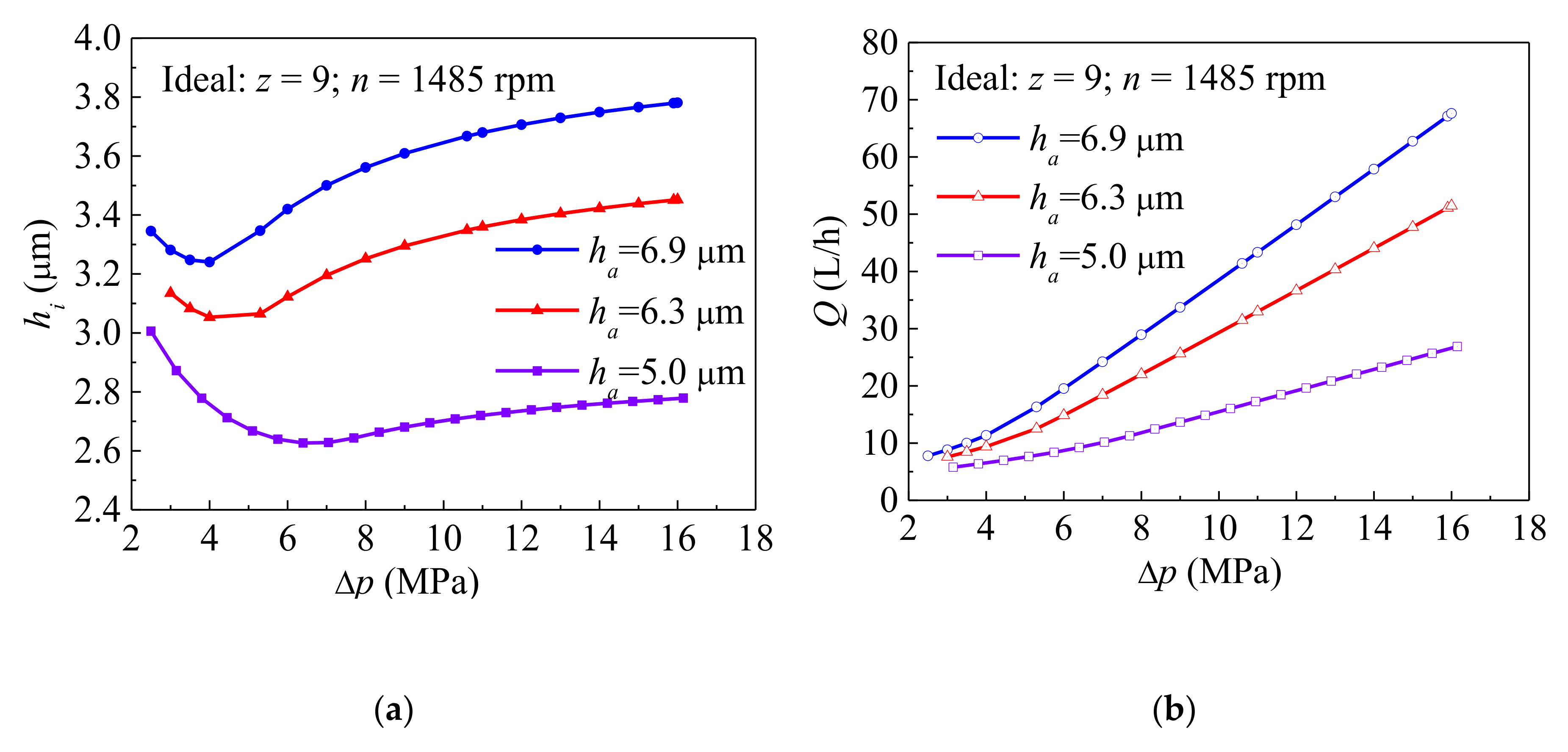
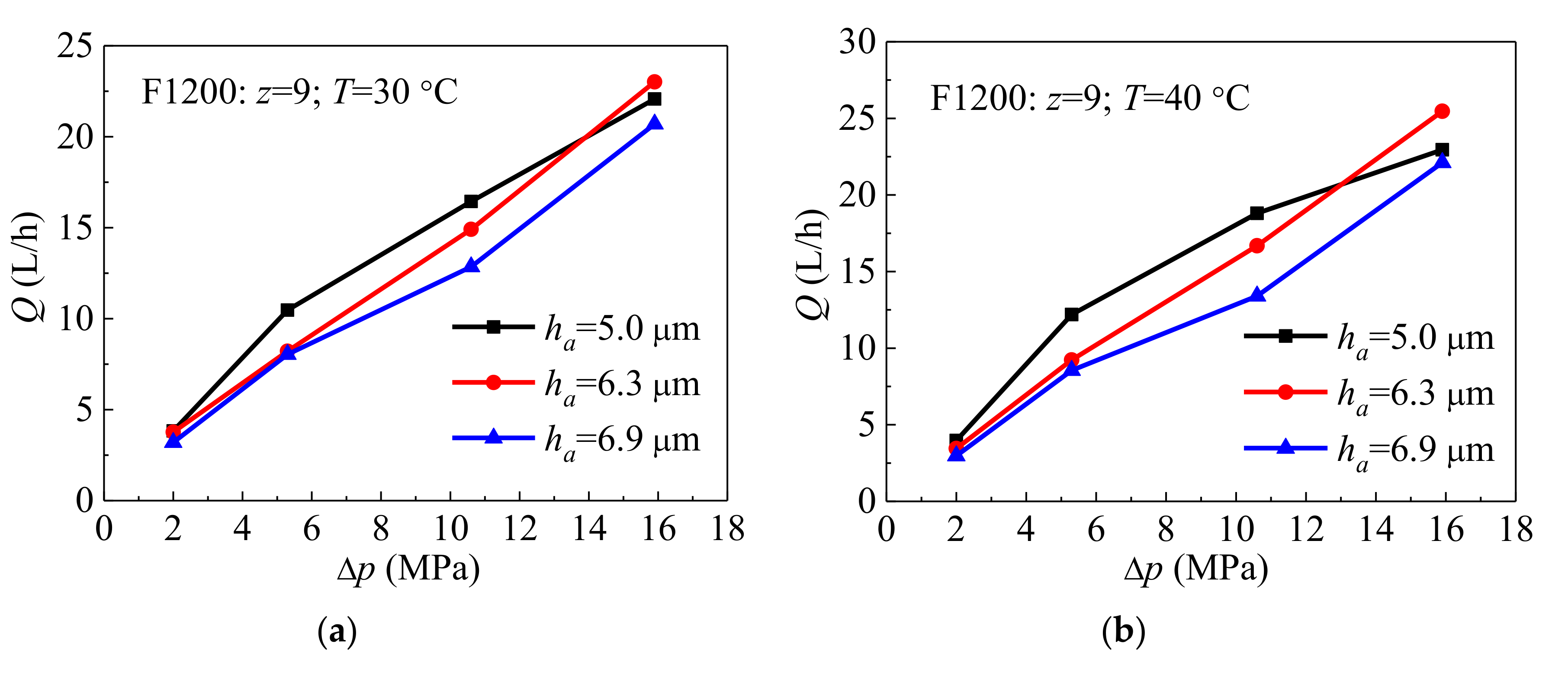
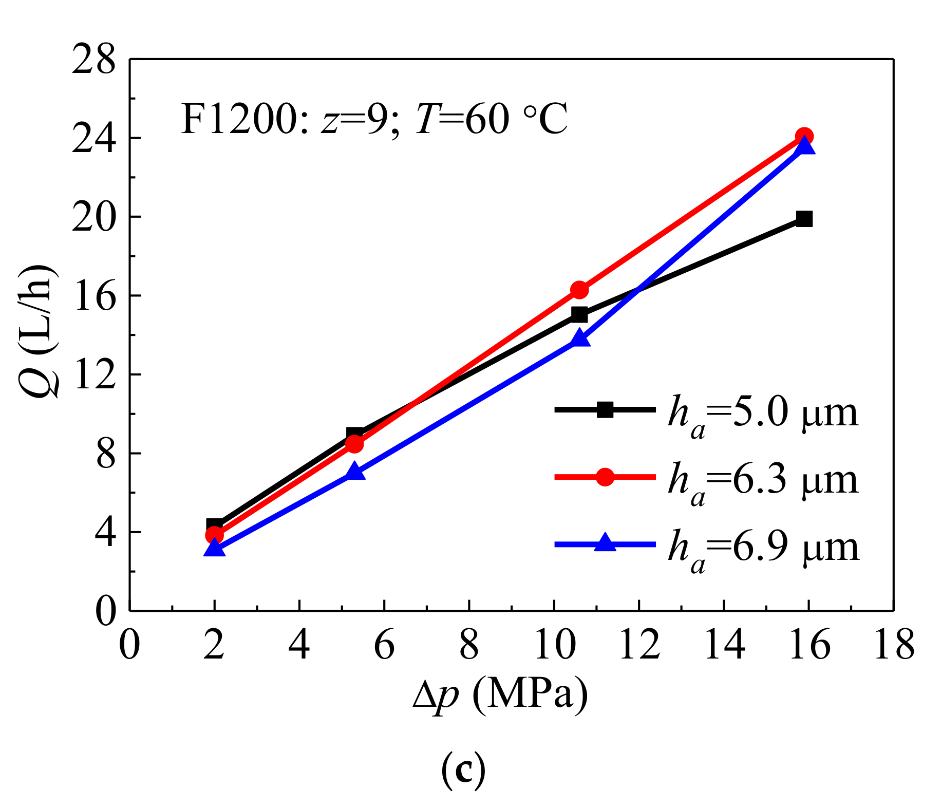
  • The calculated results show that when the waviness amplitude is constant, the leakage rate increases linearly with the increase of the pressure. The minimum liquid film thickness decreases first and then increases with the decrease of the pressure. There is a minimum limit value due to the phenomenon of liquid film cavitation. The larger waviness amplitude led to the smaller thickness of the liquid film and the larger leakage rate under the same pressure.
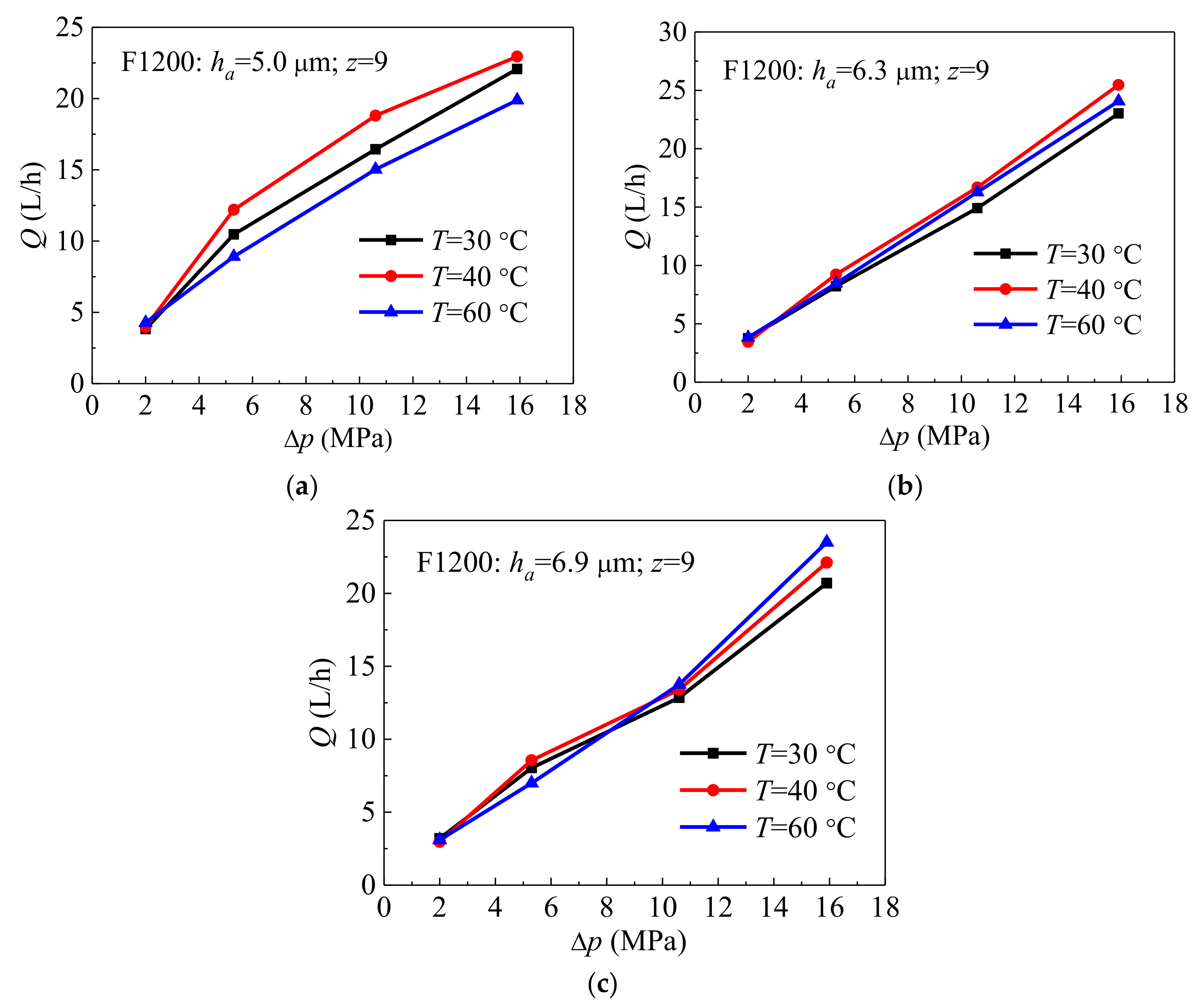
  • The test results show that the leakage rate is basically stable under the steady-state conditions and increases with pressure. The sealing performance is superior during the step-up and step-down processes of the pressure, and the seal ring does not lock up, which indicates the operation stability of the waviness end face seal.
  • The test pressure, temperature and waviness amplitude have important effects on the leakage rate of the mechanical seal. The effect of the sealing pressure is the largest, and the influence of the temperature and waviness amplitude is not obvious, which is caused by the complex thermo-mechanic coupling effect of the mosaic for the rotating and stationary slide ring, and the inconsistency of the temperature control during the test.
  • The calculated value of the leakage rate is greater than the measured value, which indicates that the thermo-mechanics coupling effect of the rotating and stationary slide rings for the mechanical seal cannot be ignored. The accurate calculation of the thermal deformation of the seal waviness end face is very important for the prediction of the leakage rate. The waviness mechanical seal needs to be further developed by multi-physics coupling modelling analysis.

Author Contributions

X.F.: conceptualization, methodology, software, validation, formal analysis, data curation, visualization, writing—original draft, writing—review & editing; W.S.: supervision, formal analysis, investigation, resources, project administration, funding acquisition; Y.M.: conceptualization, validation, formal analysis, investigation, resources, data curation, writing—review & editing, project administration, funding acquisition; L.W.: software, validation, formal analysis, data curation; H.T.: formal analysis, investigation, writing—review & editing. All authors have read and agreed to the published version of the manuscript.

Funding

This research was funded by Natural Science Foundation of Heilongjiang Province of China, Grant number E2018018; National Natural Science Foundation of China, Grant number 51976043 and National Natural Science Foundation of China, Grant number 11875330.

Conflicts of Interest

The authors declare no conflict of interest.

References

  1. Allaire, P.E. Noncontacting Face Seals for Nuclear Applications—A Literature Review. Lubr. Eng. 1984, 40, 344–351. [Google Scholar]
  2. Hu, S.T.; Huang, W.F.; Liu, X.F.; Wang, Y.M. Influence Analysis of Secondary O-ring Seals in Dynamic Behavior of Spiral Groove Gas Face Seals. Chin. J. Mech. Eng. 2016, 29, 507–514. [Google Scholar]
  3. Wang, Y.; Sun, J.J.; Tao, K.; Ma, C.B.; Tu, Q.A. Numerical Analysis of T-groove Dry Gas Seal and Groove Optimization. Tribology 2014, 34, 420–427. [Google Scholar]
  4. Iny, E.H. A Theory of Sealing with Radial Face Seals. Wear 1971, 18, 51–69. [Google Scholar]
  5. Cochain, J. Numerical and Experimental Study of Misaligned and Wavy Mechanical Face Seals Operating under Pressure Pulses and Pressure Inversions. Ph.D. Thesis, Université de Poitiers, Poitiers, France, 2018. [Google Scholar]
  6. Cochain, J.; Brunetière, N.; Parry, A.; Denoix, H.; Maoui, A. Experimental and Numerical Study of Wavy Mechanical Face Seals Operating under Pressure Inversions. Proc. Inst. Mech. Eng. Part J J. Eng. Tribol. 2020, 234, 247–260. [Google Scholar]
  7. Shen, M.X.; Peng, X.D.; Meng, X.K.; Zheng, J.P.; Zhu, M.H. Fretting Wear Behavior of Acrylonitrile-butadiene Rubber (nbr) for Mechanical Seal Applications. Tribol. Int. 2016, 93, 419–428. [Google Scholar]
  8. Varney, P.; Green, I. Impact Phenomena in a Noncontacting Mechanical Face Seal. J. Tribol. 2017, 139, 022201. [Google Scholar]
  9. Lebeck, A.O. Principles and Design of Mechanical Face Seals; Wiley: Hoboken, NJ, USA, 1991. [Google Scholar]
  10. Lebeck, A.O. Mechanical Loading—A Primary Source of Waviness in Mechanical Face Seals. ASLE Trans. 1977, 20, 195–208. [Google Scholar]
  11. Lebeck, A.O. A Test Apparatus for Measuring the Effects of Waviness in Mechanical Face Seals. ASLE Trans. 1981, 24, 371–378. [Google Scholar]
  12. Lebeck, A.O. Hydrodynamic Lubrication in Wavy Contacting Face Seals—A Two Dimensional Model. J. Tribol. 1981, 103, 578. [Google Scholar]
  13. Etsion, I. The Effect of Combined Coning and Waviness on the Separating Force in Mechanical Face Seals. J. Mech. Eng. Sci. 2006, 22, 5964. [Google Scholar]
  14. Liu, Y.; Liu, W.; Li, Y.; Liu, X.; Wang, Y. Mechanism of a Wavy-tilt-dam Mechanical Seal under Different Working Conditions. Tribol. Int. 2015, 90, 43–54. [Google Scholar]
  15. Lebeck, A.O.; Young, L.A. Wavy-tilt-dam Seal Ring and Apparatus for Shaping Seal Rings. U.S. Patent No. 4,887,395, 1989. [Google Scholar]
  16. Salant, R.F.; Payne, J.W.; Johnson, W.R.; Boles, G. Simulation of a Hydraulically Controllable Reactor Coolant Pump Seal. Tribol. Int. 2018, 122, 163–168. [Google Scholar]
  17. Gustafsson, T.; Hakula, H.; Leinonen, M. Stochastic Galerkin Approximation of the Reynolds Equation with Irregular Film Thickness. Comput. Math. Appl. 2017, 74, 1590–1606. [Google Scholar]
  18. Chandramoorthy, N.; Hadjiconstantinou, N. A Reynolds Lubrication Equation for Dense Fluids Valid Beyond Navier-Stokes. In Proceedings of the 69th Annual Meeting of the APS Division of Fluid Dynamics, Portland, Oregon, 20–22 November 2016. [Google Scholar]
  19. Liu, W.; Liu, Y.; Huang, W.F.; Suo, S.F.; Wang, Y.M. Effect of Disturbances on the Dynamic Performance of a Wavy-tilt-dam Mechanical Seal. Tribol. Int. 2013, 64, 63–68. [Google Scholar]
  20. Liu, W.; Liu, Y.; Wang, Y.; Peng, X. Parametric Study on a Wavy-tilt-dam Mechanical Face Seal in Reactor Coolant Pumps. Tribol. Trans. 2011, 54, 878–886. [Google Scholar]
  21. Liu, W.; Liu, Y.; Zhai, J.; Huang, W.; Wang, Y. Three-dimensional Flow–heat Coupling Model of a Wavy-tilt-dam Mechanical Seal. Tribol. Trans. 2013, 56, 1146–1155. [Google Scholar]
  22. Djamaï, A.; Brunetière, N.; Tournerie, B. Numerical Modeling of Thermohydrodynamic Mechanical Face Seals. Tribol. Trans. 2010, 53, 414–425. [Google Scholar]
  23. Brunetière, N.L.; Tournerie, B.; Jean Frêne, J. Tehd lubrication of Mechanical Face Seals in Stable Tracking Mode: Part 2—Parametric Study. J. Tribol. 2003, 125, 617–627. [Google Scholar]
  24. Li, Z.D.; Hao, M.; Yang, W.; Han, J.; Ren, B. Effects of Waviness and Taper on Cavitation Characteristics of Liquid Lubricated Mechanical Seals. CIESC J. 2016, 67, 2005–2014. [Google Scholar]
  25. Huo, F.W. Ultra-precision Grinding of the Complex Surfaces of Hydrodynamic Seal Rings Used in Reactor Coolant Pumps. J. Mech. Eng. 2012, 48, 184. [Google Scholar]
  26. Huo, F.W. Ultra-precision Grinding of the Wavy-tilt-dam Seal Rings Used in Reactor Coolant Pumps. J. Mech. Eng. 2013, 49, 154. [Google Scholar]
  27. Feng, G.; Guo, D.M.; Huo, F.W.; Jin, Z.J.; Kang, R.K. Implementation Strategies for High Accuracy Grinding of Hydrodynamic Seal Ring with Wavy Face for Reactor Coolant Pumps. Sci. China Technol. Sci. 2013, 56, 2403–2412. [Google Scholar]
  28. Han, C. Study on Process of Wolfram Carbide Sealing Ring with Waviness Surface by Accurate Grinding; National University of Defense Technology: Changsha, China, 2011. [Google Scholar]
  29. Wang, X.X. Mechanism Analysis and Experimental Study on Combined Coning and Waviness Mechanical Face Seal for Nuclear Reactor Coolant Pump; Tsinghua University: Beijing, China, 2011. [Google Scholar]
  30. Feng, X.D.; Ma, Y.; Song, K.L.; Tan, H.P.; Li, M.Q.; Lyu, Y.G. Engineering Development and Application of Hydrodynamic Mechanical Seal of Reactor Coolant Pump. Nucl. Power Eng. 2019, 40, 142–145. [Google Scholar]
  31. Meng, X.K.; Bai, S.X.; Peng, X.D. An Efficient Adaptive Finite Element Method Algorithm with Mass Conservation for Analysis of Liquid Face Seals. J. Zhejiang Univ. Sci. A 2014, 15, 172–184. [Google Scholar]
Figure 1. Schematic of the mechanical seal, including (a) mechanical seal configuration and (b) stationary slide ring (SSR).
Processes 08 01611 g001
Figure 2. Model of the sealing gap.
Processes 08 01611 g002
Figure 3. Comparison of minimum fluid film thickness hi (a) and leakage rate Q (b), including waviness amplitude ha. The viscosity is taken as 1.003 × 10⁻³ kg/(m·s).
Processes 08 01611 g003
Figure 4. Manufacture status of the stationary slide rings, including (a) δ = 0.12 mm, (b) δ = 0.15 mm, (c) δ = 0.20 mm.
Processes 08 01611 g004
Figure 5. Measurement of the waviness amplitude, including (a) δ = 0.12 mm, (b) δ = 0.15 mm, (c) δ = 0.20 mm.
Processes 08 01611 g005
Figure 6. Test rig.
Figure 6. Test rig.
Processes 08 01611 g006
Figure 7. The leakage rate with different waviness amplitudes, including (a) ha = 5.0 μm, T = 30 °C, (b) ha = 5.0 μm, T = 40 °C, (c) ha = 5.0 μm, T = 60 °C, (d) ha = 6.3 μm, T = 30 °C, (e) ha = 6.3 μm, T = 40 °C, (f) ha = 6.3 μm, T = 60 °C, (g) ha = 6.9 μm, T = 30 °C, (h) ha = 6.9 μm, T = 40 °C, (i) ha = 6.9 μm, T = 60 °C.
Processes 08 01611 g007aProcesses 08 01611 g007b
Figure 8. The comparison of the leakage rate at different temperature, including (a) ha = 5.0 μm, (b) ha = 6.3 μm, (c) ha = 6.9 μm.
Processes 08 01611 g008
Figure 9. The comparison of the leakage rate at different waviness amplitude, including (a) T = 30 °C, (b) T = 40 °C, (c) T = 60 °C.
Processes 08 01611 g009aProcesses 08 01611 g009b
Table 1. Geometric and operating parameters.
ItemValue
Outer radius Ro (mm)152
Inner radius Ri (mm)138.55
Dam radius Rd (mm)141.5
Numbers of waviness z9
Waviness amplitude ha (μm)5.0; 6.3; 6.9
Balance ratio0.745
Outer pressure po (MPa)2.0; 5.3; 10.6; 15.9
Inner pressure pi (MPa)0
Pressure difference Δp = popi (MPa)2.0; 5.3; 10.6; 15.9
Rotor speed n (rpm)1485
MediumWater
Density ρ (kg/m3)998.2
Viscosity μ (kg/(m·s))1.003 × 10−3 (20 °C)
Table 2. Measuring instruments.
MeasurementIdentificationOutput SignalAccuracyRange
Medium pressureP_BW4–20 mA±1%0–25 MPa
Low-pressure leakage rateQ_LPL4–20 mA±0.5%0–100 L/h
Medium temperatureT_BW4–20 mAGrade B0–100 °C
Rotating speedS_MM4–20 mA0.01%0–2000 rpm
Table 3. Calculation and test results comparison at the different pressures.
ha/μmPressure/MPaTest Value/L·h−1Calculated Value/L·h−1
5.05.310.655.02
10.616.4415.76
15.922.0825.55
6.35.38.2212.52
10.614.9131.52
15.923.0251.11
6.95.38.0416.31
10.612.8541.40
15.923.0251.11
Publisher’s Note: MDPI stays neutral with regard to jurisdictional claims in published maps and institutional affiliations.

