Article

Numerical Investigation of an Open-Design Vortex Pump with Different Blade Wrap Angles of Impeller

1
National Research Center of Pumps, Jiangsu University, Zhenjiang 212013, China
2
School of Mechanical Engineering, Nantong University, Nantong 226000, China
*
Authors to whom correspondence should be addressed.
Processes 2020, 8(12), 1601; https://doi.org/10.3390/pr8121601
Submission received: 29 October 2020 / Revised: 25 November 2020 / Accepted: 1 December 2020 / Published: 4 December 2020

Abstract

:
The blade wrap angle of impeller is an important structural parameter in the hydraulic design of open-design vortex pump. In this paper, taking a vortex pump with a cylindrical blade structure as the research object, two kinds of different blade wrap angle of vortex pump impellers are designed. The experiment and numerical simulation research is carried out, and the results of external characteristics and internal flow field are obtained under different flow rate. The results show that when ensuring that other main structural parameters remain unchanged, the efficiency and head of open-design vortex pump increase with the blade wrap angle decreases. In the case of blade wrap angle increasing, the length of rotating reflux back from lateral cavity to inlet is longer. For the same type of vortex pump, the length of rotating reflux to inlet decreases with the increase of flow rate. At the inlet area of impeller front face, there is an area where liquid flows back to the lateral cavity. The volute section shows that after passing through the impeller and lateral cavity, the liquid is discharged to the pump outlet with strong spiral strength. It is found that the blade wrap angle decreases and the shaft power increases, while the pump efficiency increases. The impeller blade wrap angle of vortex pump can be considered to select a smaller value.

1. Introduction

Vortex pump is widely used in sewage treatment, slurries, and large particle transportation along with continuous development of industrial and agricultural production. The impeller is installed on one side of the pump cavity, and it has a wide lateral cavity, there are flow of through flow and circulation flow in the pump cavity simultaneously under the rotation of the impeller. This type of pump anti-clogging performance is better. However, this equipment exhibits disadvantages, which include low efficiency and high energy consumption [1]. At present, detailed information is still unavailable for flow fields in vortex pumps. Schivley [2] put forward a flow model to investigate internal flow of vortex pumps and pointed out that fluids can be sucked into pumps under effects of atmospheric pressure when static pressure is negative at central region of the vortex. There is a lateral cavity in the vortex pump, and the impeller has no front cover. Hence, the vortex pump anti-clogging performance is better than that of general centrifugal pumps. However, the pump efficiency is relatively low [3,4,5].
Numerical simulations of different end clearance conditions were carried out while ensuring that other design parameters remain unchanged.
The influence of pump structure on its performance was experimentally studied by Zheng [6]. A new method was developed in which the volumetric ratio of the lateral cavity to the impeller was used to design vortex pumps. According to the statistics of a number of experimental data, the authors believe that the pump can get a good performance in the ratio between 3 and 5. Sha et al. [7] combined theory and experiment to derive a unified experience coefficient for use of hydraulic design method on vortex pump, further analyzed the hydraulic model, and inferred experience coefficient for least-square equation of centrifugal slurry and vortex pumps. Liu et al. [8] obtained the influence of the special volute structure of the vortex self-priming pump on its self-priming performance through 2D PIV and numerical calculation. The results show that the combination of the guide wall and the impeller outlet promotes the gas-water mixing and the formation of bubble flow, and improves the self-priming performance. To understand flow conditions in vortex pumps, Alexander Steinmann carried out numerical and experimental investigations [9], with further objective of investigating URANS-CFD (Unsteady Reynolds-Averaged Navier–Stokes -Computational Fluid Dynamics) method using cavitation model for numerical stability and accuracy.
The experiments on changing the axial location of impeller by Sha et al. [10,11], and measurement of flow field in lateral cavity with five-hole probe were conducted on a self-built vortex pump. Based on the experiments, the characteristic performance curves and the absolute velocity, the circumferential velocity, the radial velocity, the axial velocity, and the flow static pressure were obtained. The experimental results proved that the cavitation characteristic curve showed opposite tendency in the operating conditions of small charge compared with centrifugal pump and anti-cavitation were improved with the increase of the scale that impeller was inserted into lateral cavity. In order to study the influence of end clearance of impeller on the performance of a multi-stage pump, a change end clearance of impeller method was studied through CFD by Zhou et al. [12] to analyze performances of pump. The results show that the existence of end clearance, which leads to the flow aggravation separation in the diffuser passage, and further reduces the performance of the pump. The wear characteristics of slurry pump are studied based on particle model under low flow conditions by Peng et al. [13]. The results showed that there was serious local wear in the interface between the sheath and the rotor near the tongue under small flow condition. By removing the front and rear back blades, the wear degree at the junction can be effectively reduced, but the wear of the inner side of the front guard board will be intensified. The author established the apparatus first for measuring the velocity distribution on the axial vertical profile in vortex pump impeller and pressure distribution on blade surface [14]. The measuring methods are explained in more detail and the measured results are presented. An exploratory study on numerical calculation of solid–liquid two-phase flow by Gao et al. [15], the numerical calculation of vortex pump base on CFD-DEM (Discrete Element Model) coupling calculation method, and numerical simulation was carried out under different particle sizes and concentrations, then the rapeseed was used for solid particles to the experiment, and obtained that the values of inlet rotating reflux length under different flow rate conditions. The slurry pump was used to investigate into influences of blade camber profile on pump hydraulic performance and impeller wear characteristic in terms of limestone-water slurry as transported medium [16]. The relationships of both hydraulic performance and wear characteristic with blade camber profile were analyzed numerically in Fluent 16.0 by using discrete phase model (DPM) model. The results show that the cylindrical blade designed by the logarithmic spiral method with variable angle can improve hydraulic efficiency, but will lead to a slight reduction in the head. Wear characteristics in centrifugal pump simulation method are based on DPM model and semi empirical wear model by Zhao et al. [17]. The main wear positions of the centrifugal pump structure components are obtained.
At present, the research on this kind of vortex pump with special structure is scarce. Especially in the open-design vortex pump, if the improper blade wrap angle of impeller was chosen, impeller passage partial blockage and wear will occur, causing performance reduction. Even the pump passage will be blocked and operation is stopped. Therefore, the appropriate blade wrap angle of impeller is crucial for the performance and operation of the vortex pump. This article took a typical open-design vortex pump as the research object, and designed two different type of blade wrap angle of impeller. Numerical simulations of different blade wrap angle of impeller conditions were carried out. The test validated the effect of impeller blade wrap angle on vortex pump performance and also provided a reference for impeller design and engineering application.

2. Calculation Model
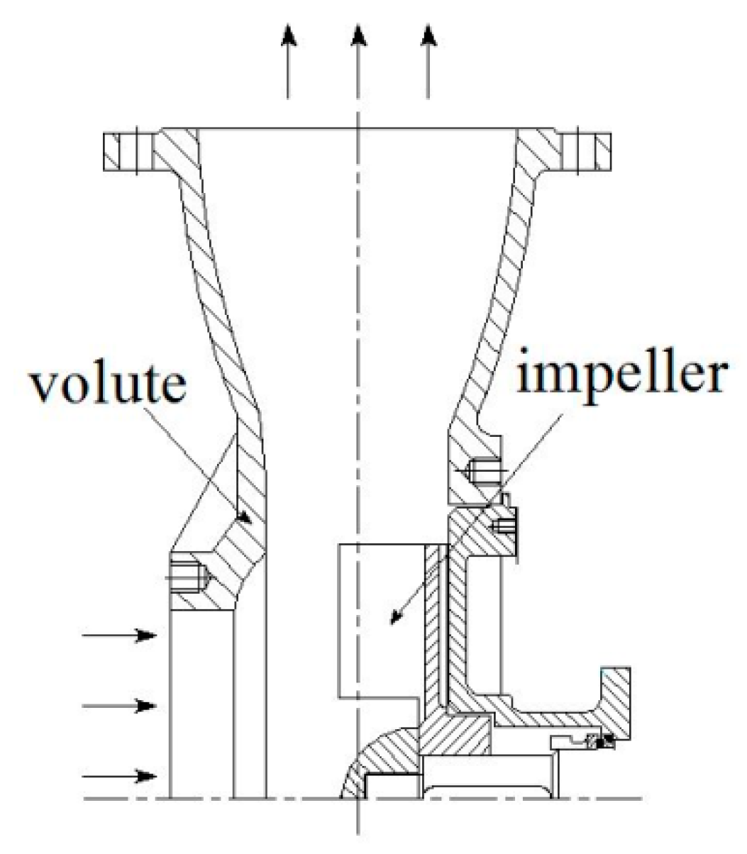
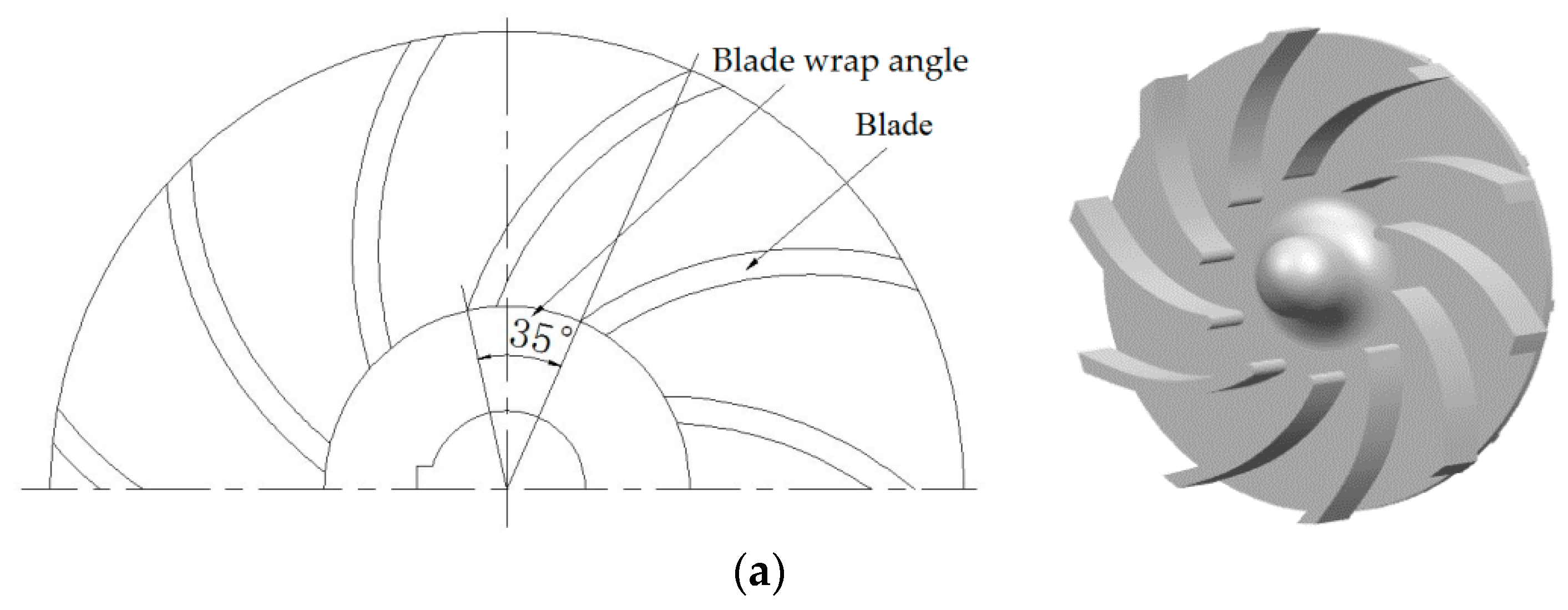
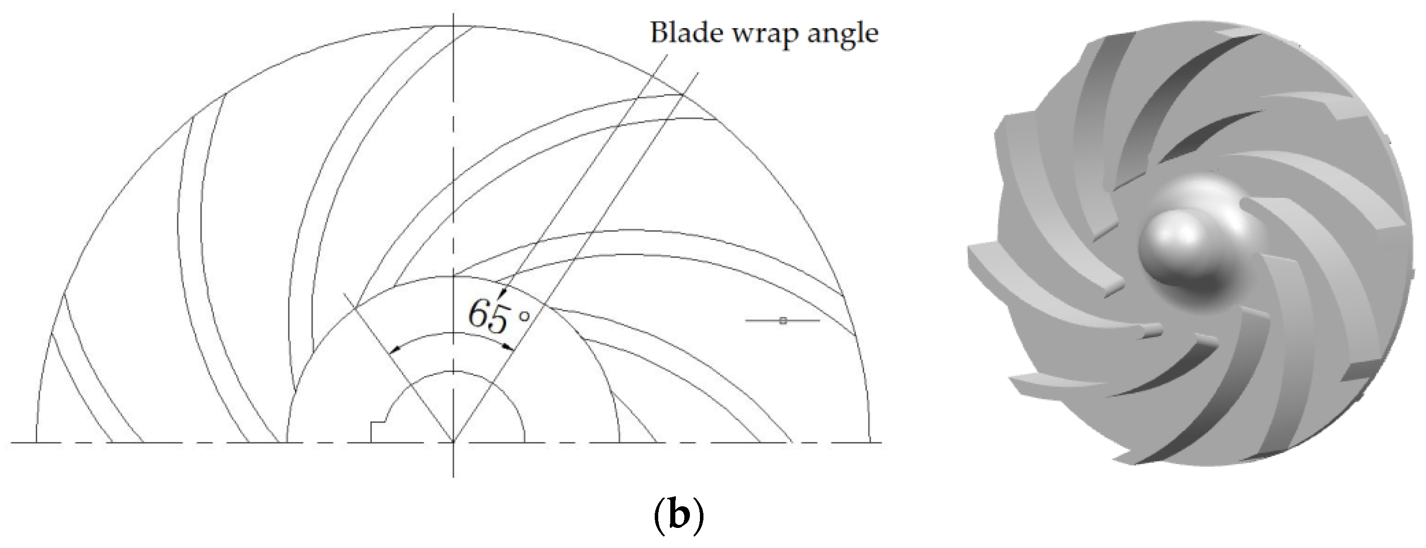
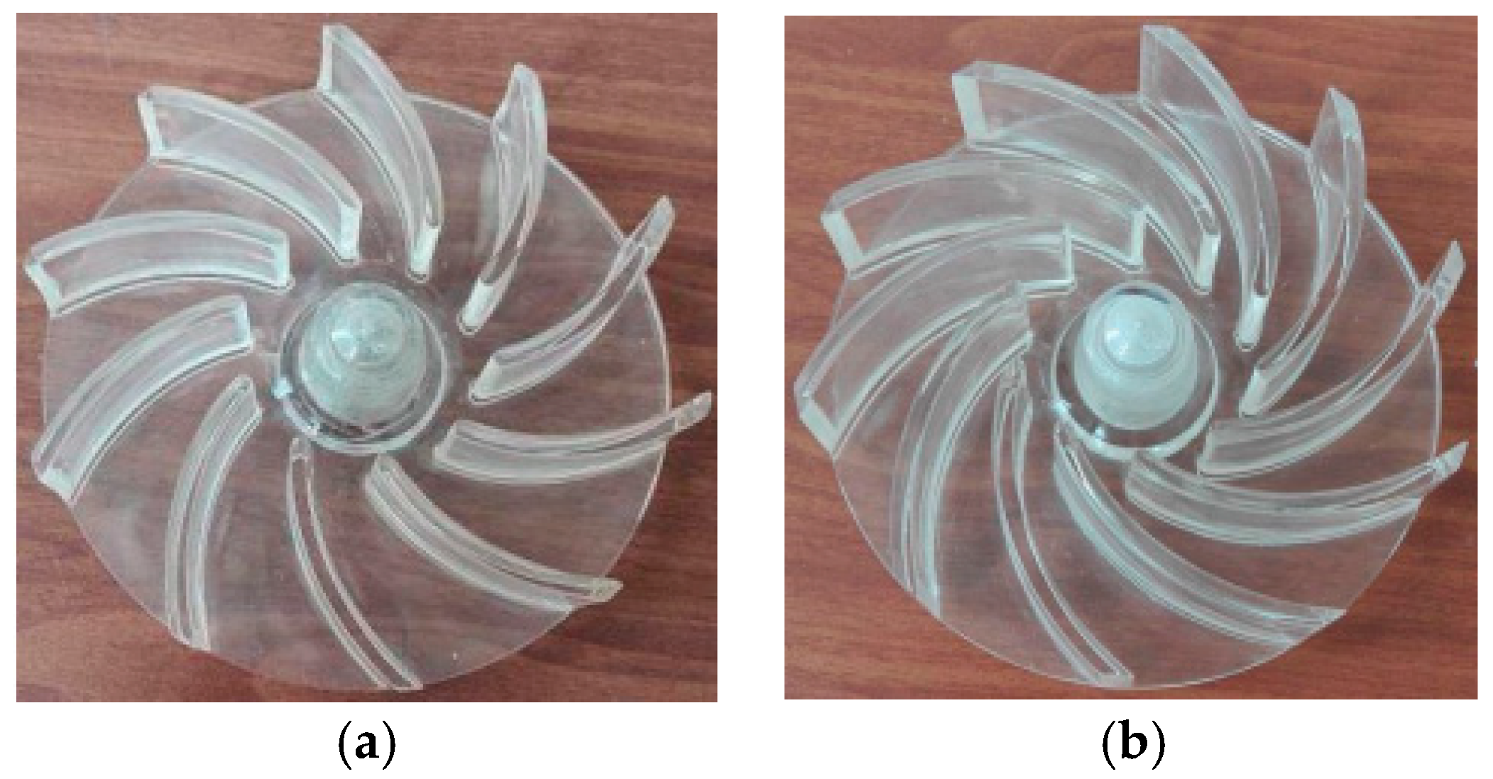
2.1. Physical Model

An open-design vortex pump with a specific speed of 166 was selected as the research object. The design flow rate was Qdes = 400 L/min; rated speed n = 1485 r/min. The main impellers structural parameters are shown in Table 1. Figure 1 shows the vortex pump two-dimensional assembly. The blade wrap angle of impeller as shown in Figure 2. In order to facilitate comparative analysis, numerical simulations of different impeller blade wrap angle conditions were carried out with the main impeller parameters unchanged.

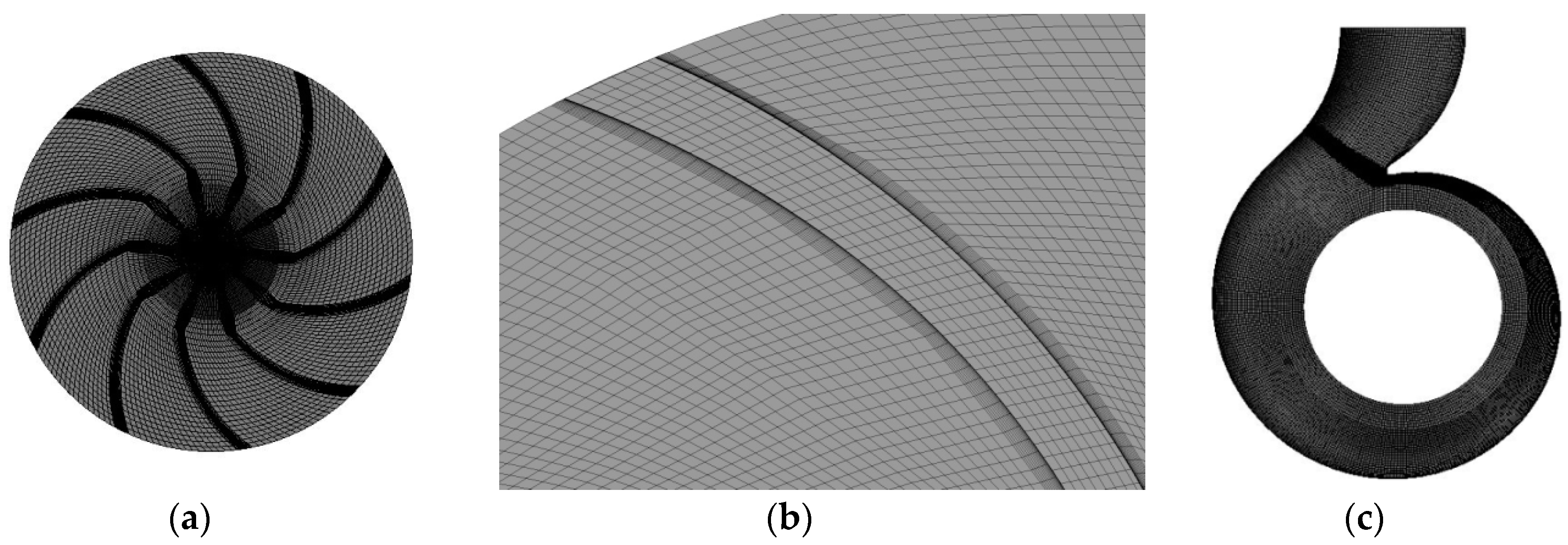
2.2. Grid Independence Verification

The computational domains were formed in Unigraphics NX 10.0 software by 2d hydraulic design drawing, as shown in Figure 3, The entire mesh generation was carried out in ICEM 19.0 software, as shown in Figure 4. In theory, with increase in grid element number, errors caused by grid will reduce gradually until they disappear. However, the number of grid elements cannot be too large for the reason of considering computer performance and computer time [18,19,20,21].
In this paper, model pump 1 is used for grid independence verification. The structured mesh of computational domains was built based on ANSYS-ICEM 19.0 software (Customer Number: 1079741, NASDAQ:ANSS, Cannonsburg, PA, USA). Four calculation schemes were created with different grid numbers in this paper. The efficiency and head of the pump were taken as grid independence indicators, as shown in Table 2. The values of efficiency and head of Scheme 1 and Scheme 2 are lower than that of other schemes. The efficiency and head value of Scheme 3 are close to that of Scheme 4 as the grid increased, which means that Scheme 3 had achieved the requirement of numerical precision. Hence, considering the calculation performance and calculation time of the computer, Scheme 3 was selected as the final grid scheme for numerical computation. Meanwhile, the entire computational domain 30 < y+ < 100 was ensured to meet the requirement of standard wall functions [22,23], and the y+ contour of the impeller as shown in Figure 5, and the mesh quality as Table 3. The mesh quality is shown in Table 3, when the value of mesh quality is >0.4, the percentage of the mesh is >99.9%, while the value of mesh quality is >0.67, the percentage of the mesh is >90%.

2.3. Numerical Algorithm

The calculation domain of pump is divided into two types of subdomains in CFD numerical simulation, which includes a total of five subdomains as shown in Figure 3, namely inlet section, lateral cavity, impeller, volute, and outlet section, and the interfaces are formed between different subdomains. The first type of subdomain includes the inlet section, the lateral cavity, the volute, and the outlet section. The equations for this type of region are solved in a stationary framework. The second type of subdomain is the impeller, which is attached to the rotating frame and solved in a rotating framework via the multiple reference frame (MRF), and the rotational speed was set as 1485 r/min [23].
The flow through the model pump was simulated with the commercial code ANSYS-Fluent 19.0, which uses the finite volume method to solve the Reynolds averaged Navier-Stokes equations for 3D incompressible steady flow. Second order upwind discretization was used for the convective and the diffusive terms. The time dependent term scheme was second order implicit [24]. The pressure–velocity coupling was calculated by means of the SIMPLE algorithm, and the convergence precision was set to 10−5.
The mass-flow rate was specified at the inlet of the CFD domain, and the outlet boundary was assumed to be outflow. At the exit, there is an unavoidable effect on the final flow solution as a result of the boundary conditions. A reasonable length was added to the real machine geometry to avoid this effect as much as possible. At the outlet, which is roughly four impeller-diameters, the gradients of the velocity components are assumed to be zero, and all physical surfaces of the pump were set as the no-slip wall.
The maximum number of iterations is set to 20, and the convergence precision is set to 10−5. In the process of iteration, if the convergence accuracy is reached, the next iteration will be carried out. If the convergence accuracy is not reached after 20 iterations, it is also considered to have reached the convergence accuracy and automatically jumps to the next step.

2.4. Turbulence Model

Predicting the performance of fluid machinery based on CFD, different turbulence models were used to calculate the fluid machinery, and the predicted results were different. There is no universally valid turbulence model which will yield optimum results for all applications [25,26,27]. It needs to select a turbulence model most suitable for vortex pump to be calculated, and comparing the numerical results with the experimental results for validate. Five turbulence models were selected to calculate in the design condition, namely, the standard k-ε model, RNG (Re-normalization group) k-ε model, realizable k-ε model, standard k-ω model, and SST (Shear stress transfer) k-ω model.
In Table 4, the test results and the numerical results with different turbulence models were compared. Generally speaking, the RNG k-ε and SST k-ω models predict the highest pump efficiency and head, and the standard k-ε model has the lowest and most close predicted value. Thus, the standard k-ε model is chosen for the following numerical calculation. It is should be noted that the standard k-ω model also has good predicted accuracy and the lowest computational time. There is around a 10% error with the test data, the reason for the increase in calculation results was probably the neglect of mechanical and leakage losses. The calculated losses in numerical simulation are considered less than the actual losses. The difference may be that in the numerical simulation in this paper, the fluid flow in the gap of rear cover plate is simplified, neglecting the volume losses caused by gap flow.

3. Results and Discussion

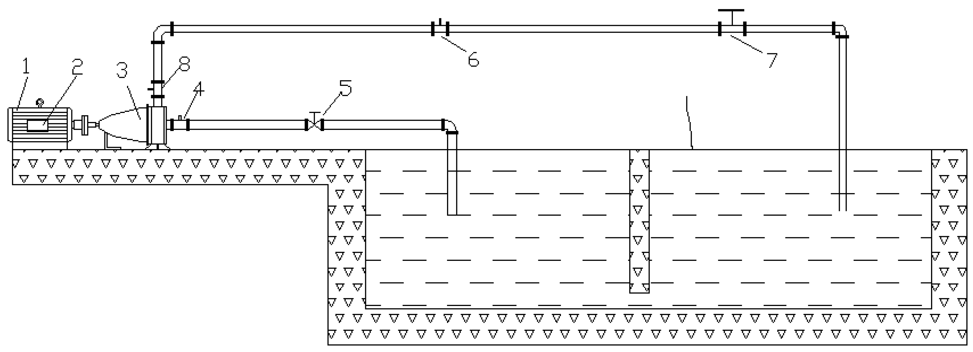
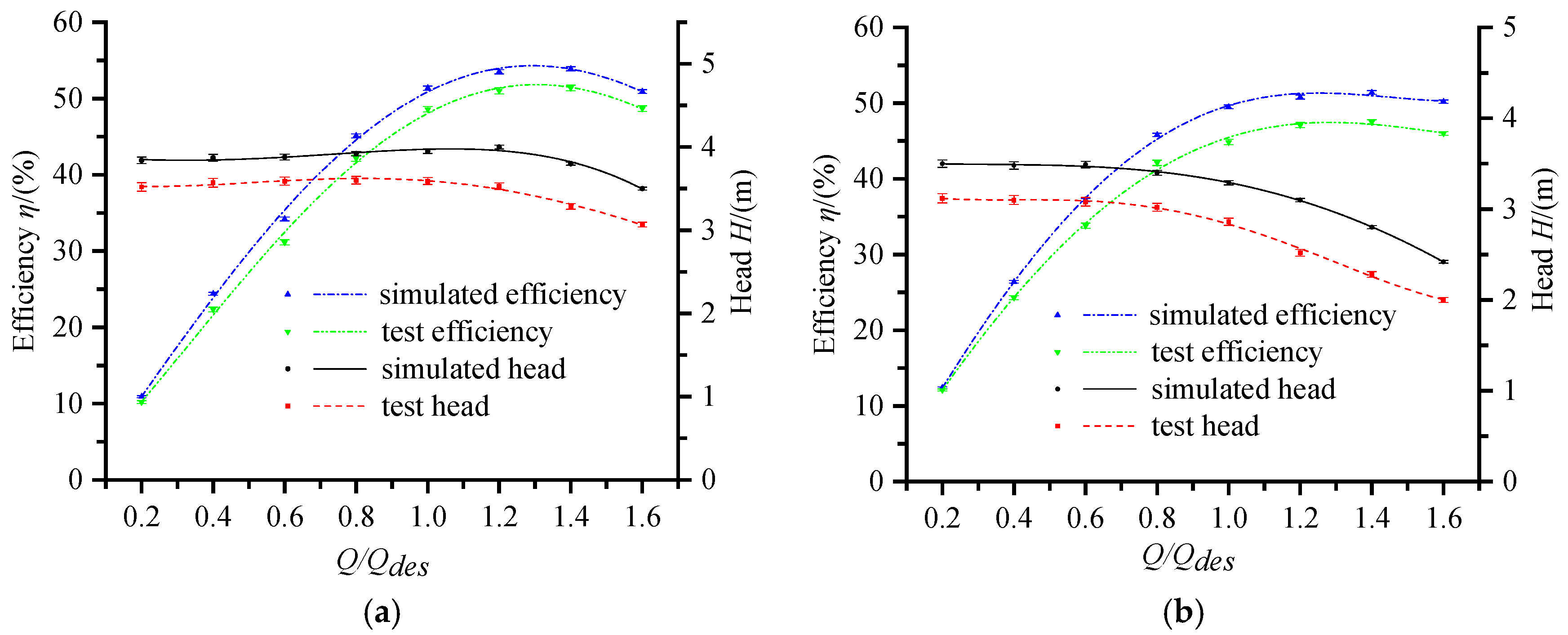
3.1. Pump Performance Test

In this paper, two impellers with different blade wrap angles are processed by polymethyl methacrylate, as shown in Figure 6. In order to continue the research later, the inlet pipeline is also processed into transparent polymethyl methacrylate. Test rig comprises two parts, namely, data acquisition system and water circulation system [28]. The open test bench is shown in Figure 7, which has the identification from the technology department in Jiangsu province of China. Test facilities and measurement methods abide by measurement requirements described [29]. It includes flow control device, data acquisition device, and data processing device. During the experiment, the flow and pressure were measured by LBBE-50S-M2X102-25 electromagnetic flowmeter (Wuxi Dihua Automation Equipment Co. Ltd., Wuxi, China) and WT2000 pressure sensor (Shanghai Welltech Automation Co., Ltd., Shanghai, China), and the shaft power was measured by JN338-20A shaft power tester (Wuxi Antok Automation Technology Co. Ltd., Wuxi, China). The range of LBBE-50S-M2X102-25 electromagnetic flowmeter is 30 L/min–850 L/min, the range of JN338-20A shaft power tester is 0–20 N m, the range of inlet pressure transmitter is −100 kpa–100 kpa; the range of outlet pressure transmitter is 0–100 kpa. Then, under the valve opening adjustment, we measure the inlet and outlet pressure and shaft power at different flow rates, and input all the signals into the computer software for calculation.
In the pump performance test, pump efficiency is defined as follows [30]:
η = ρ g Q H P S × 100 % ,
where η is pump efficiency, Q is flow rate (m3/s), H is pump head (m), and Ps is output power of motor (W).
H = p o u t p i n ρ g ,
where pin is inlet total pressure, and pout is outlet total pressure (pin and pout unit is Pa).
In this paper, experimental and numerical uncertainty analysis was performed [26,31,32]. The experimental total uncertainty is the combination of random uncertainty and systematic uncertainty, while the numerical uncertainty is caused by discretization in CFD applications. The numerical results compared to experimental results are shown in Figure 8. The performance tests under the wrap angle of the two types of impeller blades show that the efficiency and head of the impeller 1 are higher than that of the impeller 2. The numerical calculation results are in good agreement with the experimental results, and the experimental results are lower than the numerical calculation results, but the error is less than 5%. The change trend is the same under different flow. Therefore, this research method is credible. The reason for the decrease in the calculation result may be that in the numerical simulation in this paper, the fluid flow in the gap of the rear cover plate is simplified, neglecting the volume losses caused by gap flow. According to the references below, the experimental uncertainty in this study was estimated as 2.8%, the numerical uncertainty in this study was estimated as 2.1%.

3.2. Flow Field Analysis

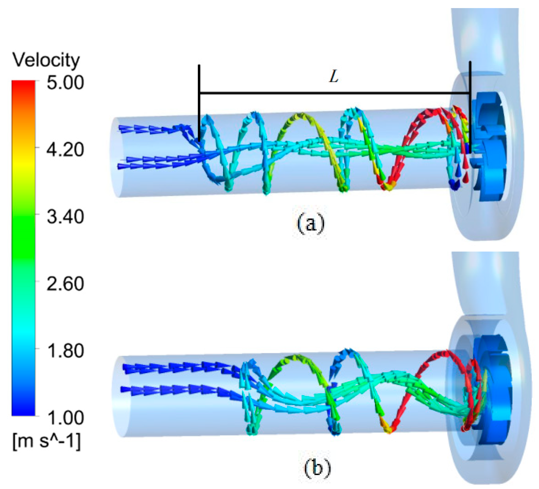
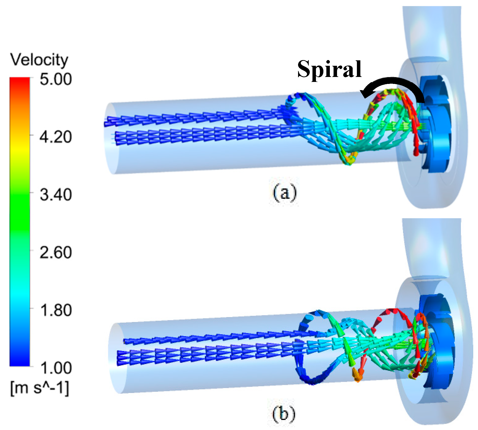
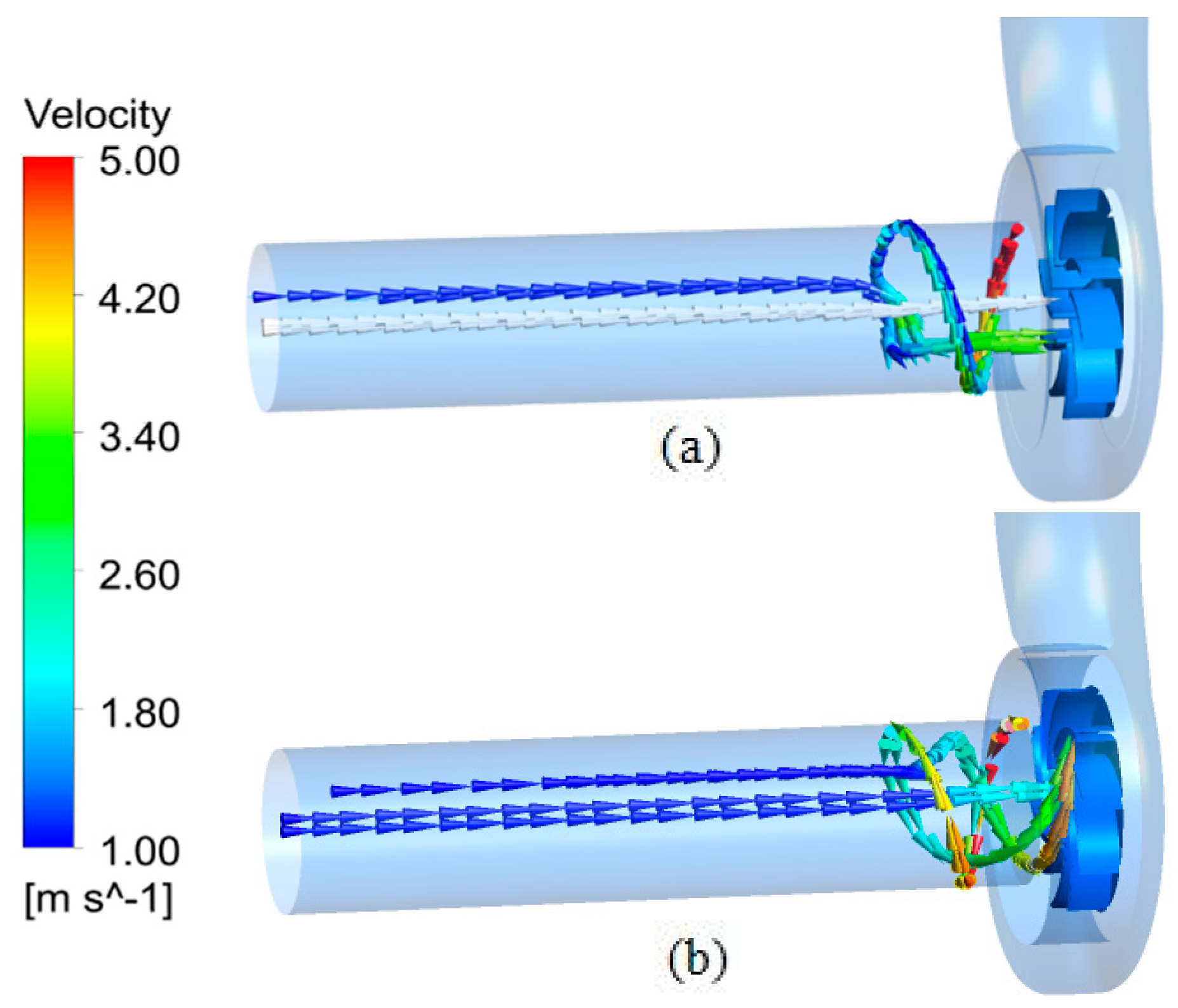
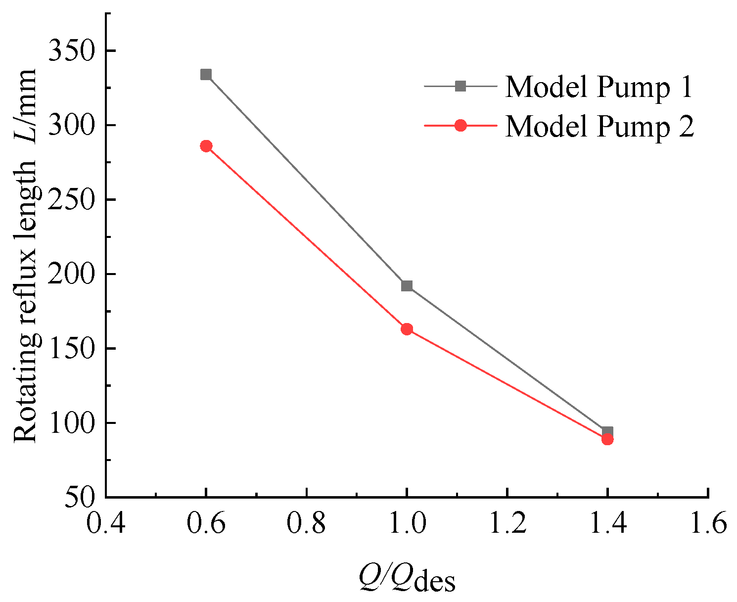
3.2.1. The Influence of Blade Wrap Angle on Inlet Backflow

At present, there are many studies on the covered design vortex pump. From the existing research conclusions, the vortex pump has both circulating flow and through flow inside. The structure of the open-design vortex pump is different from the impeller design of the covered design vortex pump. The impeller of the open-design vortex pump does not retract to the rear pump cavity, but is on one side of the pump cavity, and its internal flow mode shows different flow characteristics. In this paper, two types of vortex pump models with different impeller blade wrap angles are analyzed by numerical simulation of the full flow field.
Figure 9, Figure 10 and Figure 11 shows the flow field in inlet region of two model pumps at the flow rates of 0.6Q, 1.0Q, and 1.4Q. It can be seen from the figure that part of the medium flows backwards from the pump cavity to the inlet section along the inlet wall. The direction of rotation of the backflow is consistent with the direction of rotation of the impeller, and it enters the inlet section in a spiral form adjacent to the wall of the inlet pipe, and is constantly mixed with the incoming flow of the inlet, causing the return flow energy to gradually weaken, and finally the return flow and the incoming flow reach equilibrium and stop at a certain position. After analysis, it is found that this backflow into the inlet pipe is caused by the unique structure of the vortex pump. The unique lateral cavity of the vortex pump, and the inlet diameter of the vortex pump is larger than that of the ordinary centrifugal pump, driven by the rotation of the impeller, the lateral cavity produces a circulating flow, driven by the strength of the circulating flow, part of the backflow flows into the pump inlet segment. This part of the backflow causes a large energy loss in the vortex pump.
The values of inlet rotating reflux length under different flow rate conditions are shown in Figure 12. Through the comparison of 3 different working conditions, it can be clearly seen that the stop position of the spiral reflux moves toward the pump cavity under the large flow working condition, which is mainly caused by the increase of the flow speed and the increase of kinetic energy under the large flow working condition. At the same time, the interference degree of the flow characteristic in the middle area of the inlet pipe also decreases as the flow rate increases. Under the same flow condition, when the blade wrap angle is 35°, the value of L is longer than that of the value of blade wrap angle is 65°. Under large flow, the change of the wrap angle of the impeller blade has no obvious effect on the stop position of the inlet spiral reflux.

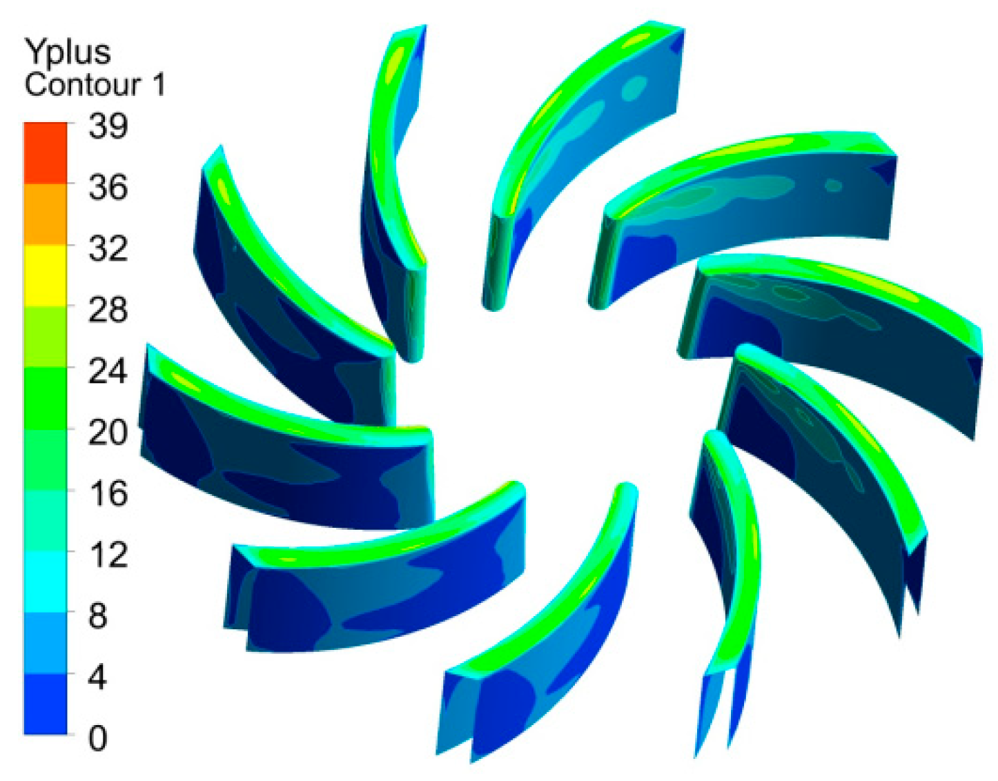
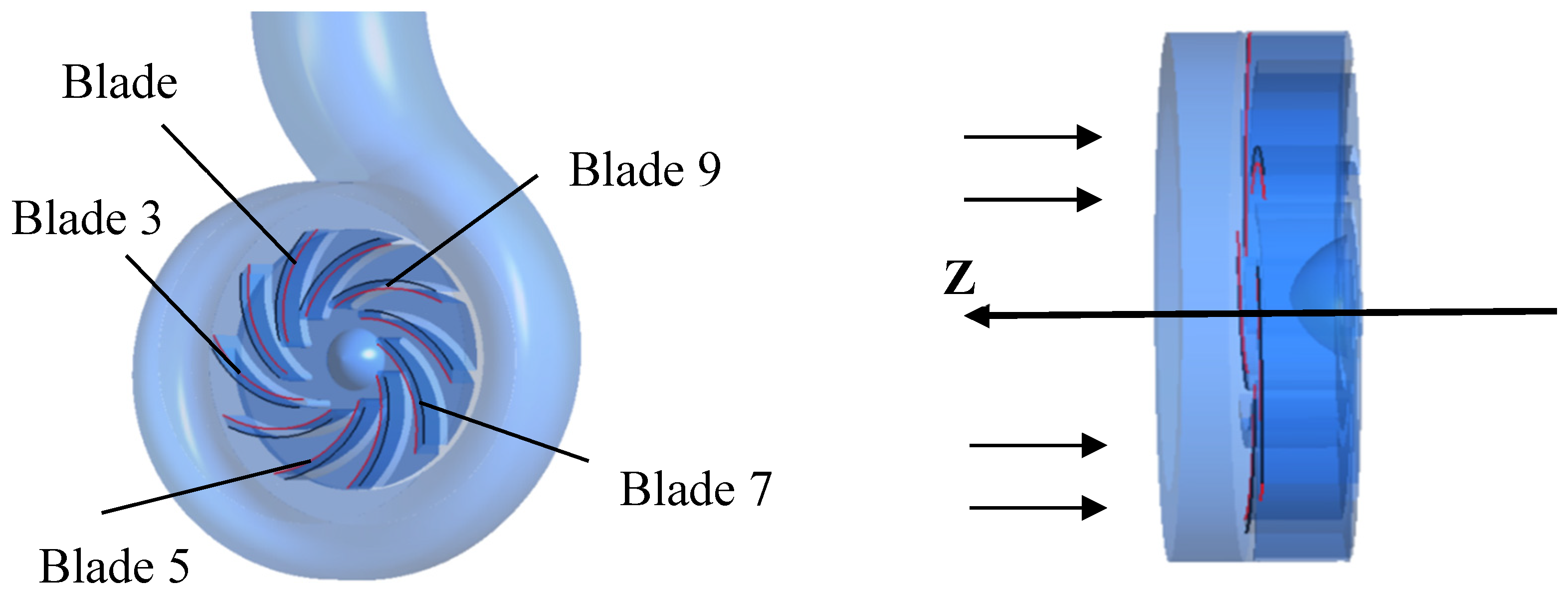
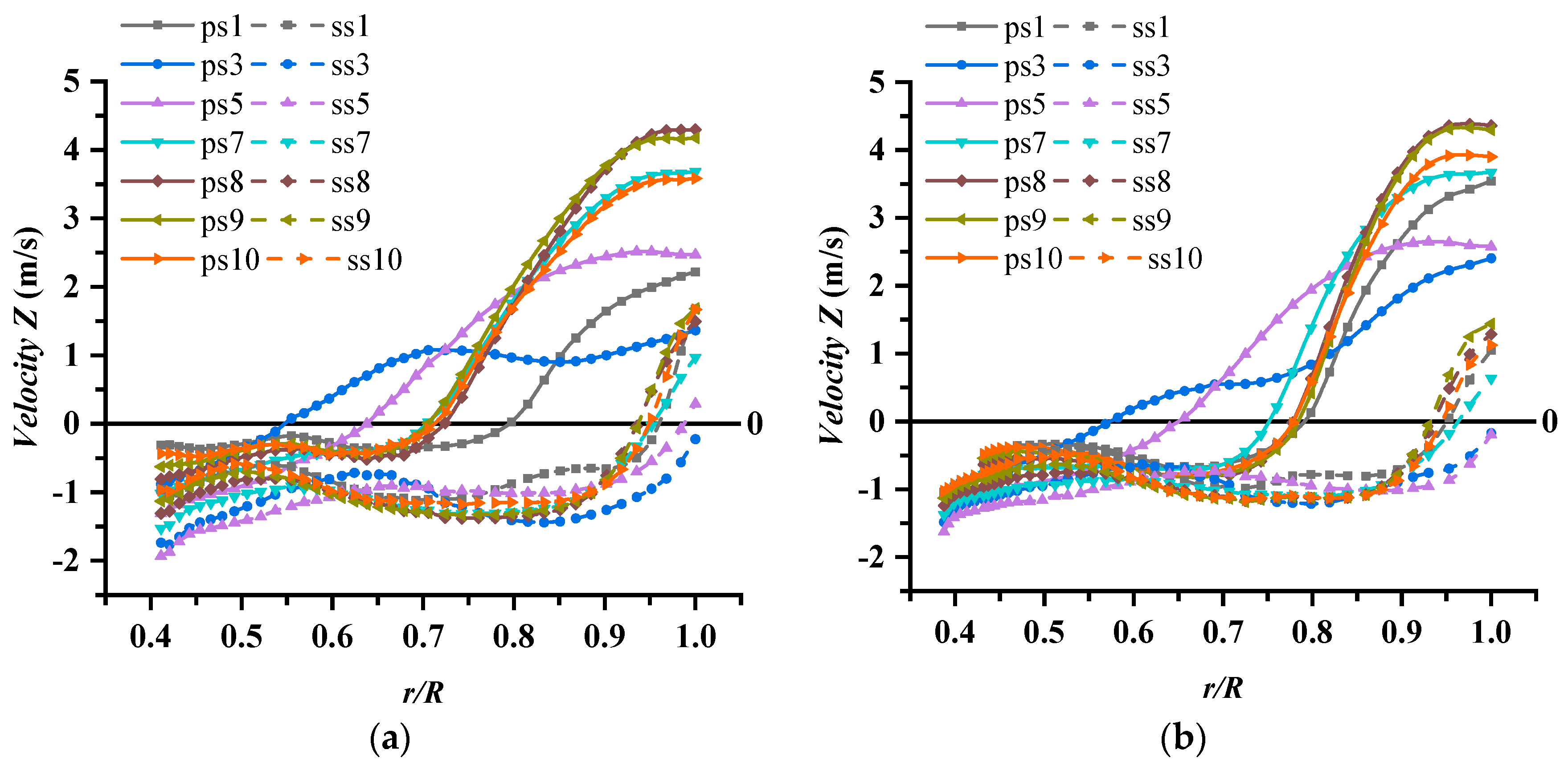
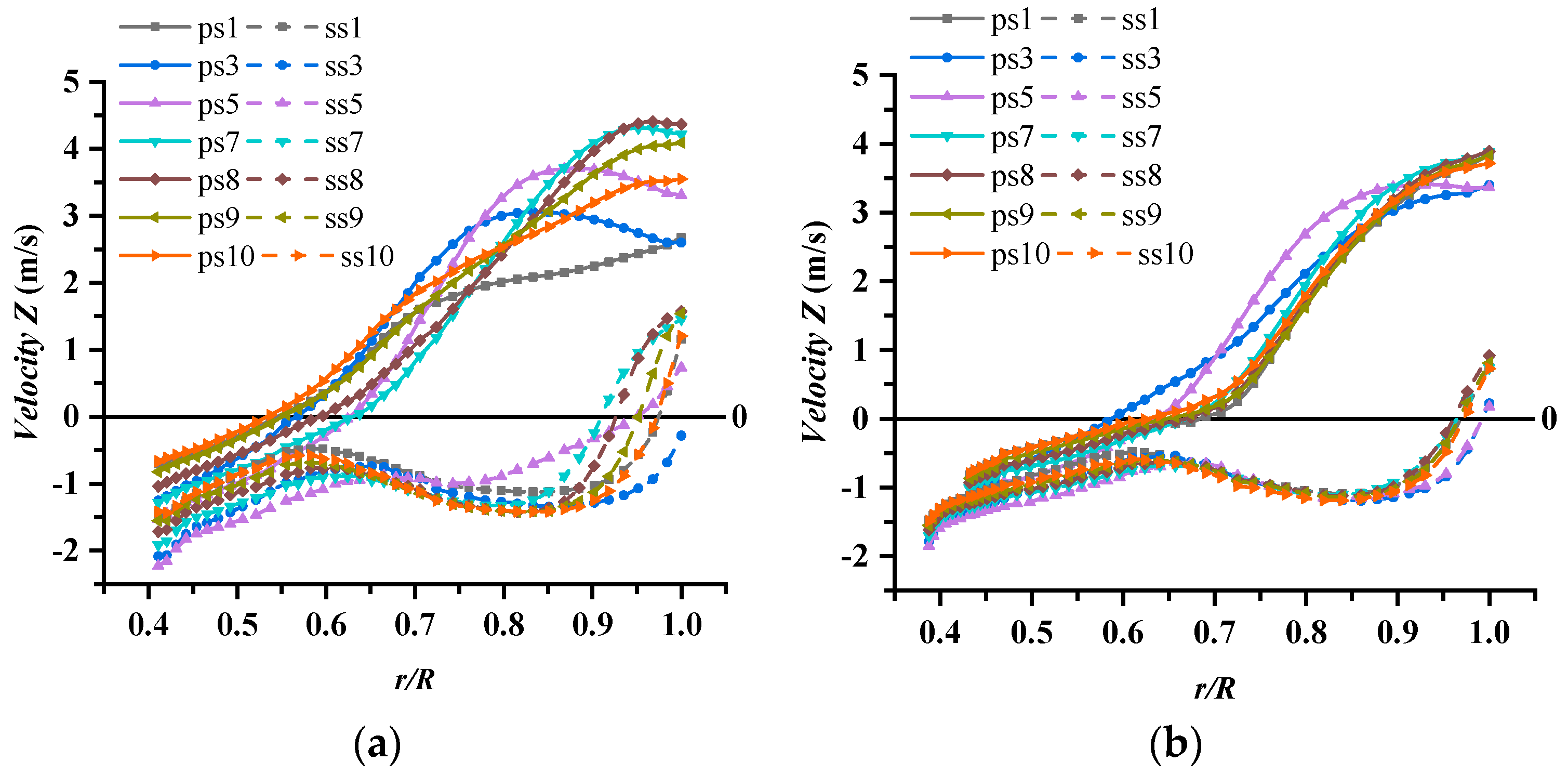
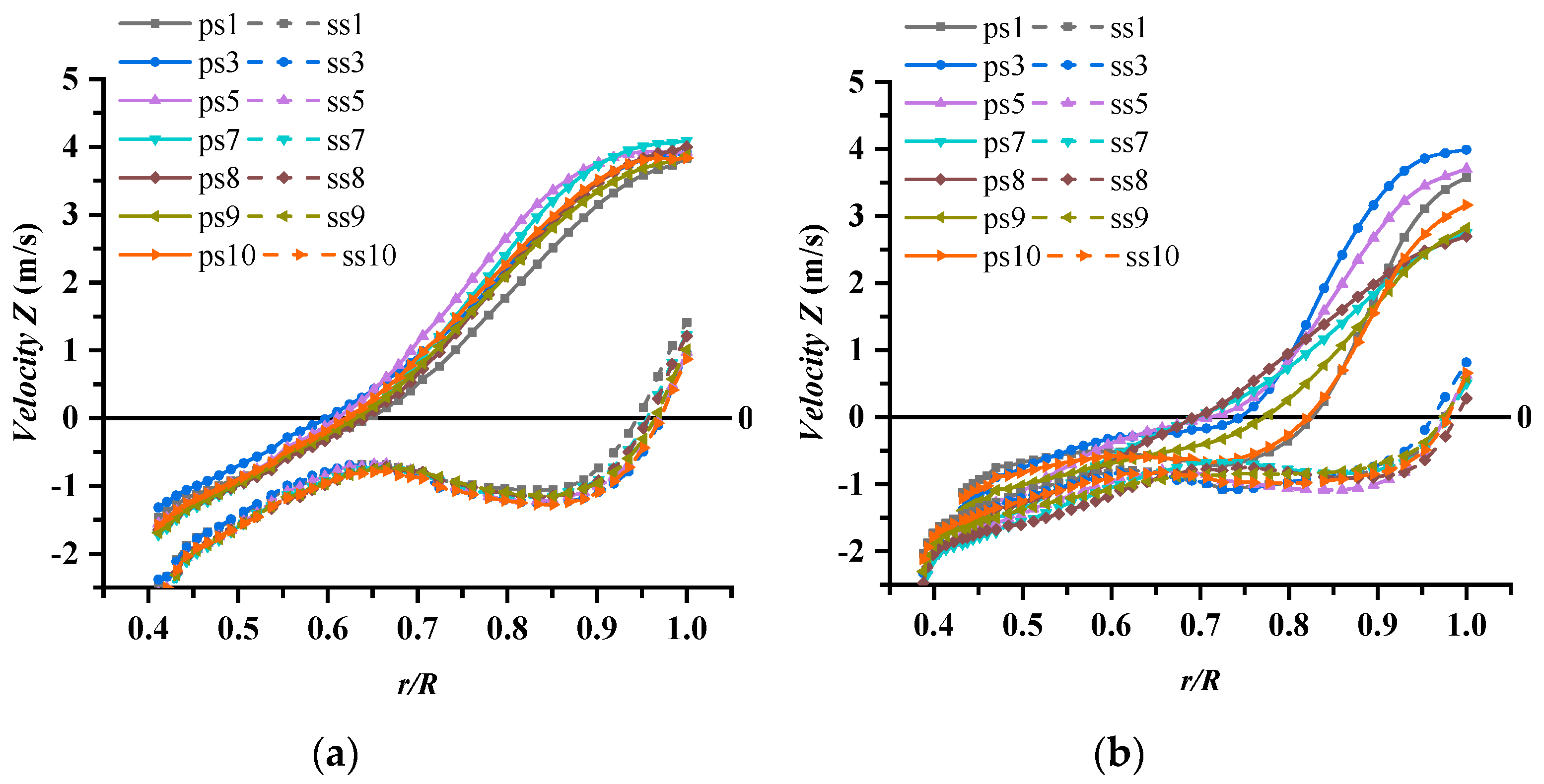
3.2.2. The Influence of the Blade Wrap Angle on the Flow Characteristic of the Impeller Front Face

In order to further explore the development process of the circulating flow in the pump cavity, focusing on the flow characteristics of the lateral cavity and the impeller, the axial velocity distribution at the impeller front face is analyzed under the two impeller blade wrap angles. The blade number is defined in Figure 13. Take the intersection line of the front face of the blade with the pressure side and the suction side respectively, and name them from blade 1 to blade 10 in turn according to the rotation direction of the impeller, and the blade 1 is located at the first section under the tongue. In Figure 14, Figure 15 and Figure 16, ps represents the intersection line of pressure side and the front face, ss represents the intersection line of the suction side and the front face. Since the positive direction of the Z-axis is set to be opposite to the inlet flow velocity during modeling, a negative axial velocity means fluid flows into the impeller, and a positive axial velocity means fluid flows from the impeller into the pump cavity. The ratio of the position of a point on the intersection line to the radius of the impeller are treated as dimensionless to indicate the relative position of the data point, that is the length–diameter ratio r/R (r represents the vertical distance from a point in the pump to the axis, R represents the radius of the impeller). The relative velocity of a point on the intersection line can be obtained by numerical simulation as shown in Figure 14, Figure 15 and Figure 16.
Due to the existence of lateral cavity, the flow characteristic in the pump cavity is more complicated than that of ordinary centrifugal pumps. The main reason is that the impeller is semi-open and has no front cover. The front face of the impeller is connected with the lateral cavity. This special structure makes the impeller area and the lateral cavity have fluid exchange flow, and the internal flow characteristic is very complicated.
A part of the fluid in the impeller passage enters the lateral cavity directly from the impeller front face. This part of the fluid contains large circumferential kinetic energy due to the rotation of the impeller, which can further drive the fluid in the pump cavity to do circumferential movement, and also affects the flow of the inlet section of pump.
It can be clearly seen from Figure 14, Figure 15 and Figure 16 that under 0.6Qdes, 1.0Qdes, and 1.4Qdes flow rate conditions, the axial velocity of the fluid at the pressure side of the impeller front face changes from negative to positive, which indicates that the fluid in the latter half of the blade begins to flow out into the lateral cavity. The flow characteristics are mainly concentrated in the middle and rear sections of the blade pressure side. Due to the large inlet pipe diameter of this type of vortex pump, the ratio of pump inlet radius to impeller radius r/R is 0.74, and the inlet flow has a greater impact on the front end of the impeller. Therefore, the value of r/R of the impeller front face is about 0.74, where the area becomes a boundary area for liquid in and out. For the suction side, except for the area after value of r/R 0.95, the values of axial velocity are negative, indicating that the liquid flow from the lateral cavity into the impeller at the entire suction side area. The axial velocity of the suction side of the blade tail turned from a negative value to a positive value, there is liquid entering the lateral cavity in this area. This phenomenon may be caused by the rotation of the impeller and the existence of circulating flow in the lateral cavity.
From the two model pumps, under small flow conditions, in the transition area between the impeller front face and the lateral cavity, the axial velocity values of the blade pressure sides show large differences, such as intersection lines of ps1, ps3 and ps5, indicating that in this area, axial velocity is disordered, while the axial velocity value of the intersection lines of suction side is relatively stable. With the increase of the flow rate, the circumferential velocity trends of the pressure side and suction side of each intersection line in the impeller front face are basically the same.
At 0.6Qdes condition, the r/R value of model pump 1 and model pump 2 is about 0.55, the liquid starts to flow out from the impeller pressure side to the lateral cavity. For model pump 2, when the value of r/R is about 0.6, the liquid starts to flow out of the impeller pressure side into lateral cavity. When the flow rate increases to 1.4Qdes, the r/R value of the model pump 1 and model pump 2 are 0.6 and 0.7, respectively, the liquid from the pressure side flow out to the lateral cavity. Thus, with the flow rate increases the r/R value, where liquid from the pressure side flow into the lateral cavity increases.

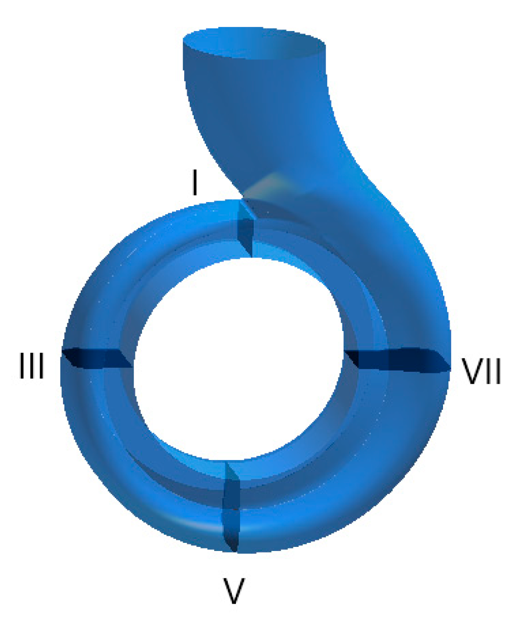
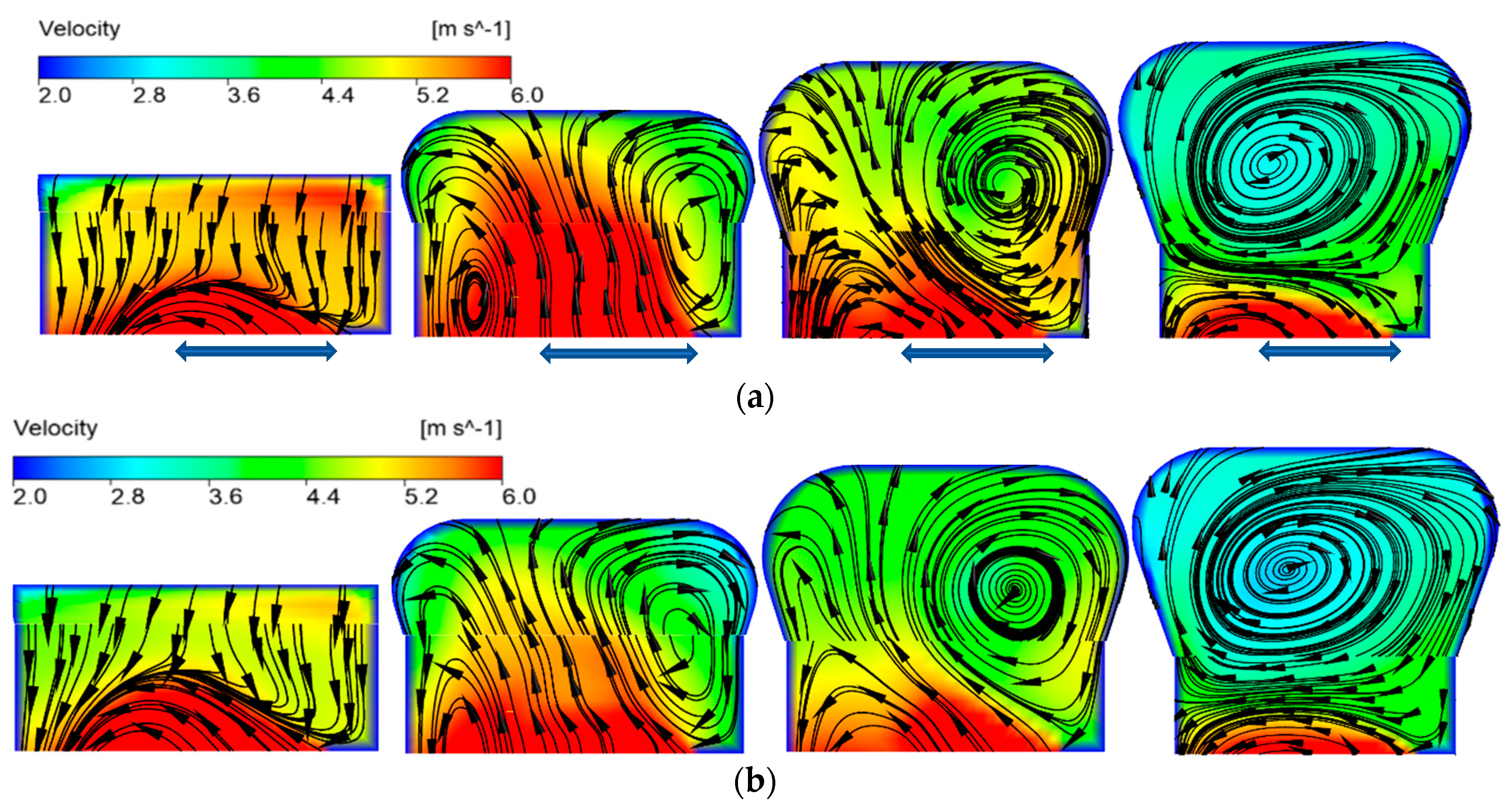
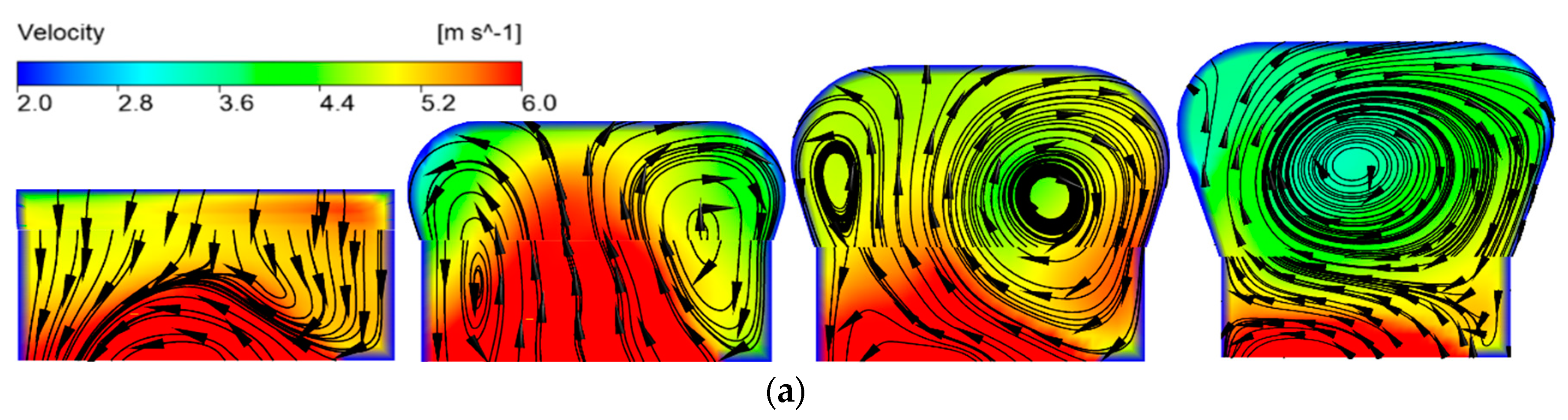
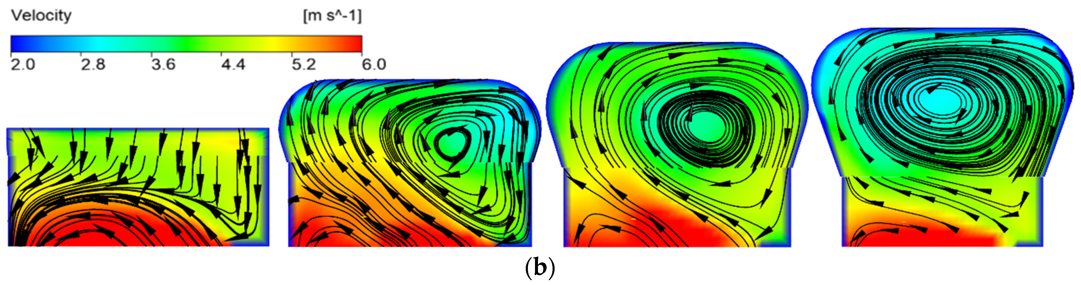
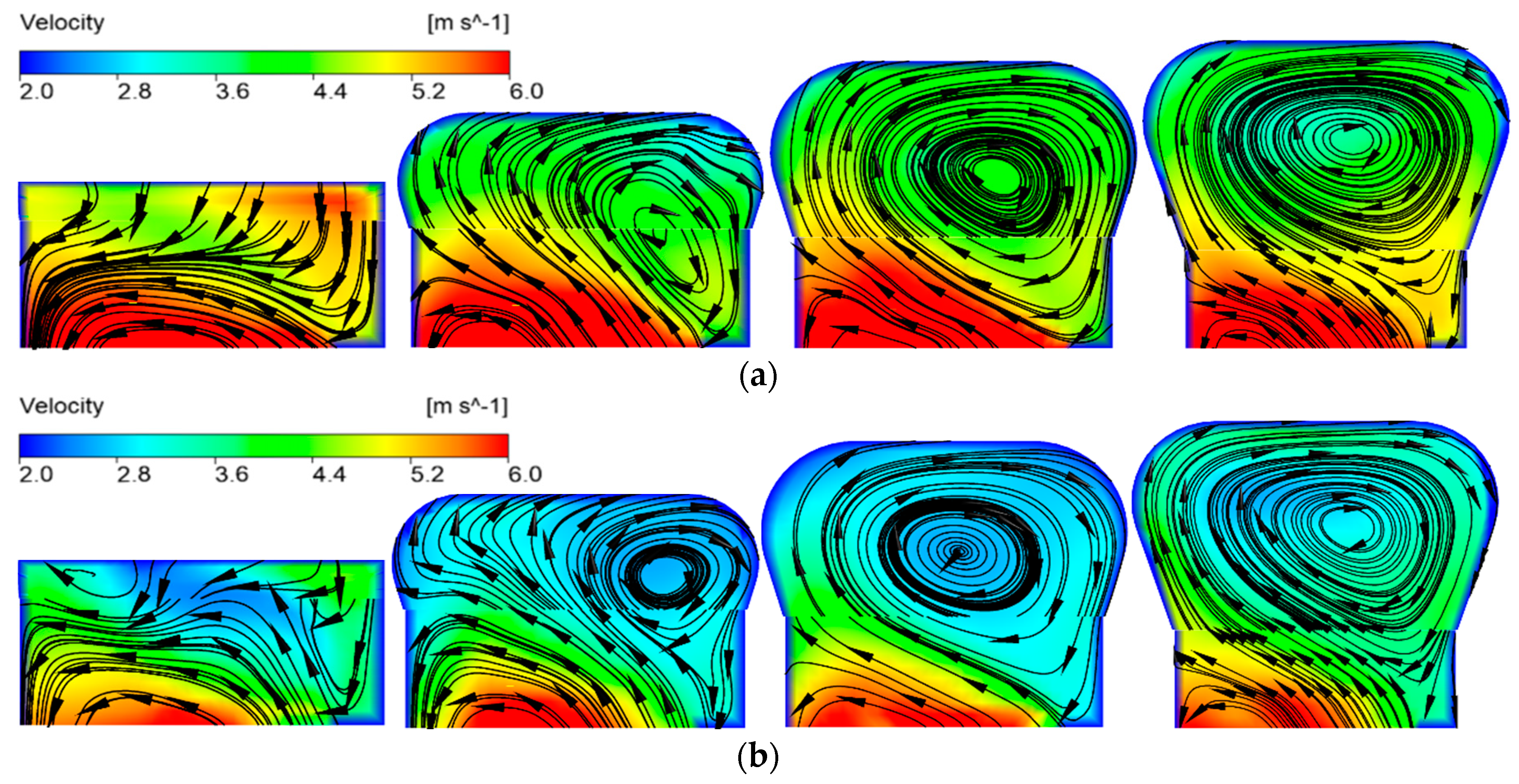
3.2.3. The Influence of Blade Wrap Angle on the Flow Characteristic inside the Volute

The vortex pump has lateral cavity and the volute is asymmetric, so it is very important to analyze the flow characteristic in the volute. In this paper, four sections of the volute were selected as shown in Figure 17, namely sections I, III, V, and VII, and analyzed for streamline velocity.
The velocity streamline contours of the four sections in volute are shown in Figure 18, Figure 19 and Figure 20. The relative velocity in the volute chamber presents non axisymmetric distribution, and the velocity in the volute decreases gradually from the first section of the volute to the outlet of the volute, which shows that the dynamic energy is gradually transformed into the pressure energy. From the first section of the volute to the outlet, the liquid entering from the impeller and the lateral cavity is discharged out of the volute outlet in a spiral flow state. Section I is at the volute tongue. Due to the blocking effect of the tongue, there is no spiral flow in the section, the spiral flow is gradually formed from the section I to the outlet of the volute. For the model pump 1, under small flow and rated flow conditions, it is found from the streamline velocity contour of section III that two spiral vortices of different sizes occur, the spiral vortex on the left is in a counterclockwise direction, the spiral vortex on the right flows in a clockwise direction. With the sectional area of the volute increases, these two spiral vortices increase. When the sectional position of the volute increases to VII, the spiral vortex on the left disappears, and the strength of the spiral vortex on the right increases to occupy the entire volute. Under the large flow rate condition, only the right side (The corresponding side of the impeller) of the volute forms a spiral vortex.
Under the same flow rate condition, the model pump 2 streamline velocity contour compares to model pump 1, it is found that at 0.6Qdes condition, there is a small spiral vortex near the wall in the left side of the III, V section, and the spiral vortex is smaller than that of model pump 1. Under the conditions of 1.0Qdes and 1.4Qdes, there is only a large spiral vortex generated on the right side of the volute. The spiral vortex on the right moves to the middle area of the volute with the increase of the volute section. When the volute section is larger than the seventh section, the spiral vortex occupies the whole volute space, and the liquid is flow to the pump outlet in a spiral shape.
Generally speaking, there is a large vortex area in the volute, which mainly occurs in the corresponding side of the impeller. Under the same flow rate condition, the velocity of the volute in model pump 2 is lower than that of model pump 1, this is consistent with the result that the head of model pump 1 is higher than that of model pump 2, which is consistent with the previous comparison and analysis of external characteristics, the previous performance curve also shows this.
As the blade wrap angle increases, the flow passage of impeller becomes narrower, and the binding force of the blade to the liquid in the passage increases, while the pump efficiency decreases. The reduced blade wrap angle can widen the flow passage and weaken the blade’s binding force to the liquid in the flow passage. It will also increase circulating flow in the lateral cavity and improve the efficiency. It is suggested that a smaller blade wrap angle should be considered.

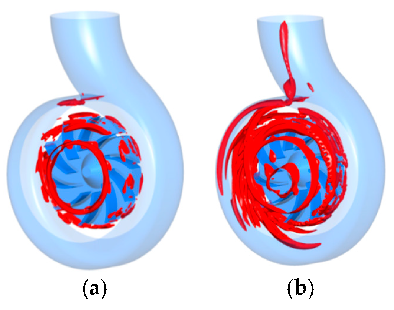
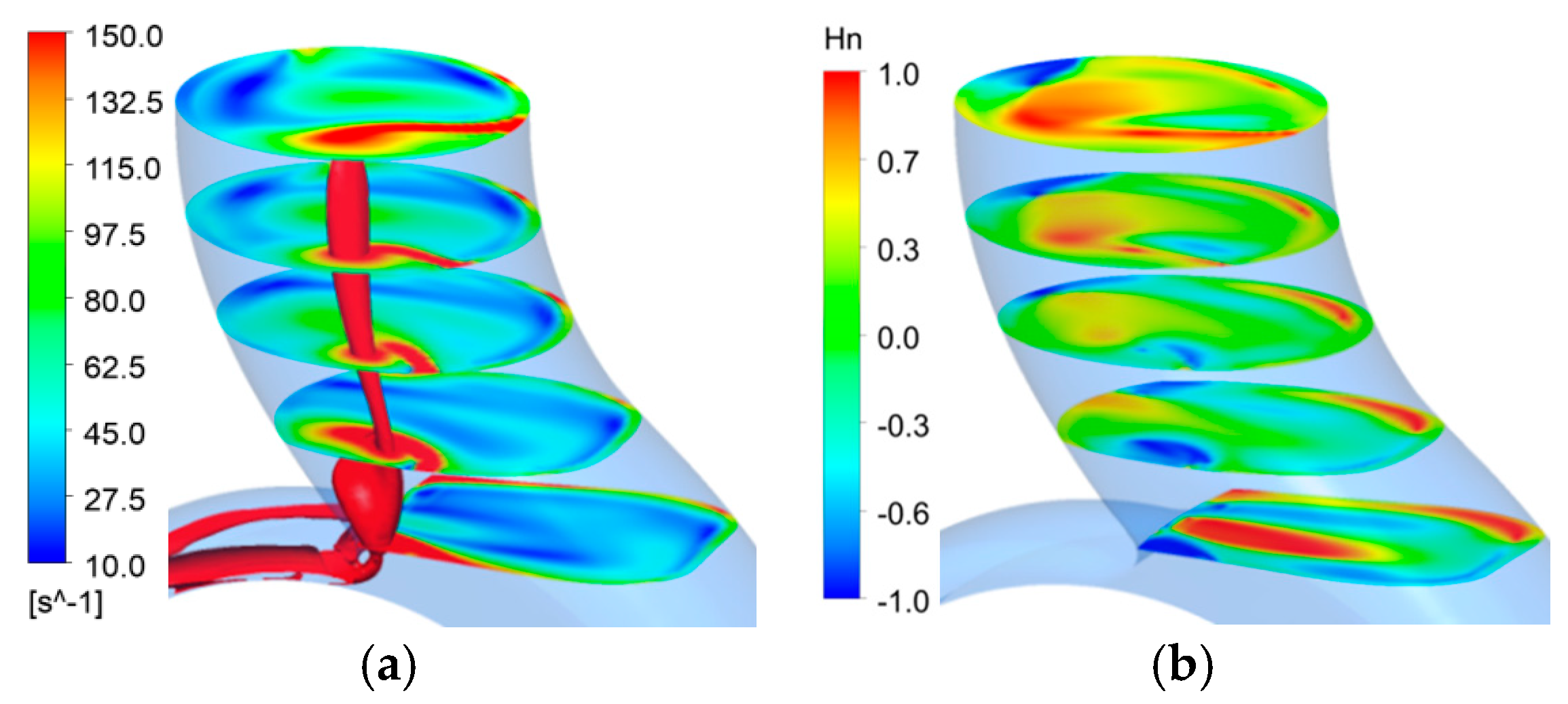
3.2.4. Vorticity Analysis in the Volute

In this paper, the regularized helicity Hn is used to determine the vortex core [33]. This method mainly captures the position of the vortex core according to the angle between the velocity vector and the vorticity. It is defined as the modeling of the point product of the velocity and the vorticity, which is used to judge the rotation direction of the vortex core. The value is [−1, 1], the vortex turns counterclockwise with positive Hn, while it turns clockwise with negative Hn [33].
H n = w · Ω | w | | Ω |
where w is relative velocity, Ω is absolute vorticity.
S i j = 1 2 ( u i x j u j x i )
  Ω i j = 1 2 ( u i x j + u j x i )
  Q = 1 2 ( Ω 2 S 2 )
where S is the strain rate tensor.
The Q criterion is selected to identify the vortex in this paper. The imaging vortex structure in the pump cavity is shown in Figure 21a,b. When Q = 54,288 s 2 , the strong vortex structure is observed in the areas of the impeller outlet volute tongue. The vortex structure of the impeller rim area is symmetrical, and there are obvious vortices in the lateral cavity near the pump inlet area. With the Q value increases to 5301 s 2 , strong vortices appear inside the volute, especially on the Sections I to V of the volute. The vortices are widely distrusted in the lateral cavity, and the vortex strength is greater near the pump inlet. The reason of the strong vortices occurring in the lateral cavity is mainly attributed to the rotation of the main flow in the cavity driven by the spinning impeller. There is a strong and wide vortex area in the entire pump cavity, mainly because the vortex pump has lateral cavity and there is circulating flow in the lateral cavity. The asymmetry of volute leads to the wide and complex vortex area in the whole pump cavity. In addition, a strong vortex appears in the tongue area and it flows to the exit of the volute due to the through flow.
Figure 22a show the vortex distribution in the volute diffuser region with Q = 5301 s 2 . Five section faces are made at an average interval of 22 mm in the volute diffuser region. It is found that there is a strong vortex flow in the diffusion region. The vortex flow occurs in the front of the volute diffuser region and moves vertically to the outlet of the volute. The formation of vortex flow may be caused by the existence of a tongue and lateral cavity. The Hn of the volute diffuser region is shown in Figure 22b, and the vortex core distribution in the volute diffuser region is relatively disordered. In particular, the vortex cores in the tongue region, and both clockwise and counterclockwise rotating vortices occurred, especially the counterclockwise rotating vortices were produced in lager area of volute diffuser region. The clockwise rotating vortices occurred in the front wall of the volute diffuser region, and the vortex cores move from the front side of the tongue to the middle side of the outlet. It was found that the liquid is discharged to the volute outlet in the form of a spiral by analyzing Figure 22.

4. Summary

In this paper, two types of vortex pumps with different impeller blade wrap angles have been numerically simulated and experimentally studied under different flow conditions. Through numerical simulation and experiments, performance curves and internal flow field results have been obtained. The conclusions include the following aspects.
(1)
Under small flow conditions, the rotating backflow at the inlet of the open-design vortex pump is more serious. With other structural parameters unchanged, when the blade wrap angle decreases, the stop position of the inlet spiral reflux increases from the pump cavity, and the hydraulic loss increases, but the efficiency and head of the vortex pump increase. The performance of the smaller impeller blade wrap angle is better than impeller performance with larger wrap angle.
(2)
In the area between the front end of the impeller and the lateral cavity of the pump, in the pressure side, the fluid flows into the impeller from the lateral cavity in the front half of impeller, and then flows out from the back half of impeller into the lateral cavity. In the suction side, the fluid in the lateral cavity flows back to the impeller. It shows that fluid flows in and out of the front face of the impeller, which leads to a decrease in hydraulic performance.
(3)
Since the impeller is installed on one side of the pump cavity, as the blade wrap angle increases, the flow passage of impeller becomes narrower, and the binding force of the blade to the liquid in the passage increases, while the pump efficiency decreases. The reduced blade wrap angle can widen the flow passage and weaken the blade’s binding force to the liquid in the flow passage. It will also increase circulating flow in the lateral cavity and improve the efficiency. It is suggested that a smaller blade wrap angle should be considered.

Author Contributions

Conceptualization, X.G. and W.S.; methodology, X.G. and W.S.; software, Y.S.; validation, H.C. and W.S.; formal analysis, X.G.; investigation, D.Z.; resources, X.G.; data curation, T.Z.; writing—original draft preparation, X.G.; writing—review and editing, W.S. and H.C.; visualization, L.Z.; supervision, W.S.; project administration, W.S.; funding acquisition, X.G. All authors have read and agreed to the published version of the manuscript.

Funding

This research was funded by the National Natural Science Foundation of China (Grant No. 51909108), National Natural Science Foundation of China (Grant No. 51979138).

Conflicts of Interest

The authors declare no conflict of interest.

Nomenclature

Qdesdesign flow rate
Qflow rate
D2impeller outer diameter
D1impeller inlet diameter
znumber of blade
ψblade wrap angle of impeller
β1impeller inlet blade angle
β2impeller outlet blade angle
Hhead
ηpump efficiency
nrated speed
nsspecific speed
ρliquid density
ggravity acceleration
Psoutput power of motor
pouttotal pressure at impeller outlet
pintotal pressure at impeller inlet
Lrotating reflux length
rvalue of the vertical distance from a point in the pump to the axis
Rimpeller radius
Hnregularize helicity
wrelative velocity
Ω absolute vorticity
Sthe strain rate tensor

References

  1. OHBA, H.; Nakashima, Y.; Shiramoto, K. A study on internal flow and performance of a vortex pump: Part 1, theoretical analysis. Trans. J. Soc. Mech. Eng. Ser. B 1983, 26, 999–1006. [Google Scholar] [CrossRef] [Green Version]
  2. Schivley, G.P.; Dussourd, J.L. An analytical and experimental study of a vortex pump. J. Basic Eng. Ser. D 1970, 92, 889–900. [Google Scholar] [CrossRef]
  3. Sha, Y.; Hou, Y. Effect of impeller position on performance and measurement of vaneless cavity flow field. J. Agric. Mach. 2010, 11, 57–62. [Google Scholar]
  4. Gerlach, A.; Thamsen, P.U.; Wulff, S.; Jacobsen, C.B. Design parameters of vortex pumps: A meta-analysis of experimental studies. Energies 2017, 1, 58. [Google Scholar] [CrossRef] [Green Version]
  5. Gao, X.; Shi, W.; Zhang, D.; Zhang, Q.; Fang, B. Optimum design and test of cyclone pump based on CFD orthogonal test. J. Agric. Mach. 2014, 5, 101–106. [Google Scholar]
  6. Zheng, M.; Yuan, S.; Chen, C. Influence of structural parameter of a vortex pump on its performance. Trans. Chin. Soc. Agric. Eng. 2000, 31, 46–49. [Google Scholar]
  7. Sha, Y.; Yang, M.; Kang, C.; Wang, J.; Chen, H. Design method and characteristic analysis of vortex pump. Trans. Chin. Soc. Agric. Eng. 2004, 36, 124–127. [Google Scholar]
  8. Liu, K.; Wang, C.; Feng, Y.; Hu, B. PIV measurements and CFD computations of internal flow characteristics of rotational flow self-priming pump. J. Drain. Irrig. Mach. Eng. 2019, 37, 1025–1030. [Google Scholar]
  9. Alexander, S.; Hendrik, W.; Alfred, O. Numerical and experimental investigations of the unsteady cavitating flow in a vortex pump. J. Hydrodyn. 2010, 22, 324–329. [Google Scholar]
  10. Sha, Y.; Hou, Y. Effect of Impeller Location and Flow Measurement in Volute of a vortex pump. Trans. Chin. Soc. Agric. Eng. 2010, 41, 57–62. [Google Scholar]
  11. Sha, Y. Experiments on performance and internal flow of a vortex pump. Trans. Chin. Soc. Agric. Eng. 2011, 27, 141–146. [Google Scholar]
  12. Zhou, L.; Wang, W.; Hang, J.; Shi, W.; Yan, H.; Zhu, Y. Numerical Investigation of a High-Speed Electrical Submersible Pump with Different End Clearances. Water 2020, 12, 1116. [Google Scholar] [CrossRef] [Green Version]
  13. Peng, G.; Zhou, G.; Hu, Z.; Zhou, H. Influence of back blade on wear of heavy slurry pump under low flow condition. J. Drain. Irrig. Mach. Eng. 2020, 38, 332–338. [Google Scholar]
  14. Chen, H. Measurement of rotating flow field with in the impeller of vortex pump. Trans. Chin. Soc. Agric. Eng. 1996, 27, 49–54. [Google Scholar]
  15. Gao, X.; Shi, W.; Shi, Y.; Chang, H.; Zhao, T. DEM-CFD Simulation and Experiment on Flow Characteristics of Particles in Vortex Pump. Water 2020, 12, 2444. [Google Scholar] [CrossRef]
  16. Li, J.; Zhang, R.; Guo, R.; Li, R. Influence of blade camber profile on hydraulic performance of slurry pump and impeller wear characteristic. J. Drain. Irrig. Mach. Eng. 2020, 38, 21–27. [Google Scholar]
  17. Zhao, W.; Zheng, Y.; Liu, Y.; Han, X. The numerical analysis of the influence of sand volume fraction on the wear characteristics of centrifugal pumps. J. Drain. Irrig. Mach. Eng. 2018, 2, 98–103. [Google Scholar]
  18. Gopalakrishnan, S. Pump Research and Development: Past, Present, and Future—An American Perspective. J. Fluids Eng. 1999, 121, 237–247. [Google Scholar] [CrossRef]
  19. Hergt, P.H. Pump Research and Development: Past, Present, and Future. J. Fluids Eng. 1999, 121, 248–253. [Google Scholar] [CrossRef]
  20. Shi, W.; Hou, Y.; Zhou, L.; Li, Y.; Xue, S. Numerical simulation and test of performance of deep-well centrifugal pumps with different stages. J. Drain. Irrig. Mach. Eng. 2019, 37, 562–567. [Google Scholar]
  21. Zhou, L.; Shi, W.; Lu, W.; Hu, B.; Wu, S. Numerical Investigations and Performance Experiments of a Deep-Well Centrifugal Pump with Different Diffusers. J. Fluids Eng. 2012, 134, 071102. [Google Scholar] [CrossRef]
  22. Fluent User’s Guide; Fluent Inc.: New York, NY, USA, 2003.
  23. Wang, F. Application of Boundary Conditions. In Computational Fluid Dynamics Analysis-CFD Principles and Application; Ying, Q., Sang, R., Eds.; Tsinghua University Press: Bejing, China, 2004; pp. 144–158. [Google Scholar]
  24. Gonzalez, J.; Parrondo, J.; Stantolaria, C.; Blanco, E. Steady and Unsteady Radial Forces for a Centrifugal Pump with Impeller to Tongue Gap Variation. J. Fluids Eng. 2006, 128, 454–462. [Google Scholar] [CrossRef]
  25. Gulich, J.F. Numerical Flow Calculations. In Centrifugal Pumps; Springer: New York, NY, USA, 2007; pp. 439–506. [Google Scholar]
  26. Celik, I.B.; Ghia, U.; Roache, P.J.; Freitas, C.J.; Coleman, H.; Raad, P.E. Procedure for Estimation and Reporting of Uncertainty Due to Discretization in CFD Applications. J. Fluids Eng. 2008, 130, 078001. [Google Scholar]
  27. Lewis, F.; Richardson, F.R.S.; Gaunt, J.A. VIII. The deferred approach to the limit. Philos. Trans. R. Soc. Lond. 1927, 226, 299–361. [Google Scholar]
  28. Benigni, H.; Jaberg, H.; Yeung, H.; Salisbury, T.; Berry, O.; Collins, T. Numerical simulation of low specific speed American petroleum institute pumps in part-load operation and comparison with test rig results. J. Fluids Eng. 2012, 134, 024501. [Google Scholar] [CrossRef]
  29. ISO 9906 Rotodynamic Pump-Hydraulic Performance Acceptance Tests-Grades 1 and 2; International Standardization Organization: Geneva, Switzerland, 1999.
  30. Guan, X. Design of Vortex Pump. In Modern Pumps Theory and Design; China Astronautic Publishing House: Beijing, China, 2010; pp. 412–420. [Google Scholar]
  31. ASME. Test Uncertainty, Standard No. PTC 19.1; The American Society of Mechanical Engineers: New York, NY, USA, 2005. [Google Scholar]
  32. Coleman, H.W.; Steele, W.G. Experimentation and Uncertainty Analysis for Engineers; Wiley: New York, NY, USA, 1989. [Google Scholar]
  33. Furukawa, M.; Inoue, M.; Saiki, K.; Yamada, K. The role of tip leakage vortex breakdown in compressor rotor aerodynamics. J. Turbomach. 1999, 3, 469–480. [Google Scholar] [CrossRef]
Figure 1. Simple diagram of pump section model.
Processes 08 01601 g001
Figure 2. Blade wrap angle of impeller. (a) Impeller 1, (b) impeller 2.
Processes 08 01601 g002aProcesses 08 01601 g002b
Figure 3. Calculation domains.
Processes 08 01601 g003
Figure 4. Sketch of the structured mesh: (a) impeller; (b) close-up view of near the trailing edge; (c) volute.
Processes 08 01601 g004
Figure 5. y+ contour of the impeller.
Processes 08 01601 g005
Figure 6. Impeller of open-design vortex pump. (a) Impeller 1; (b) Impeller 2.
Processes 08 01601 g006
Figure 7. Testing system. 1. Motor; 2. rotational speed meter; 3. test pump; 4. inlet pressure sensor; 5. inlet valve; 6. turbine flowmeter; 7. outlet valve; 8. outlet pressure sensor.
Processes 08 01601 g007
Figure 8. Comparison of pump performance between numerical and experimental results. (a) Model pump 1; (b) model pump 2.
Processes 08 01601 g008
Figure 9. 0.6Qdes condition. (a) Impeller 1; (b) Impeller 2.
Processes 08 01601 g009
Figure 10. 1.0Qdes condition. (a) Impeller 1; (b) Impeller 2.
Processes 08 01601 g010
Figure 11. 1.4Qdes condition. (a) Impeller 1; (b) Impeller 2.
Processes 08 01601 g011
Figure 12. The values of inlet rotating reflux length under different flow rate conditions.
Processes 08 01601 g012
Figure 13. Schematic of blade number.
Processes 08 01601 g013
Figure 14. 0.6Qdes condition. (a) Model pump 1; (b) model pump 2.
Processes 08 01601 g014
Figure 15. 1.0Qdes condition. (a) Model pump 1; (b) model pump 2.
Processes 08 01601 g015
Figure 16. 1.4Qdes condition. (a) Model pump 1; (b) model pump 2.
Processes 08 01601 g016
Figure 17. Volute sections.
Processes 08 01601 g017
Figure 18. 0.6Qdes streamline diagram of volute section. (a) Model pump 1; (b) model pump 2.
Processes 08 01601 g018
Figure 19. 1.0Qdes streamline diagram of volute section. (a) Model pump 1; (b) model pump 2.
Processes 08 01601 g019aProcesses 08 01601 g019b
Figure 20. 1.4Qdes Streamline diagram of volute section. (a) Model pump 1; (b) model pump 2.
Processes 08 01601 g020
Figure 21. Vortex structures of pump cavity: (a) Q = 54,288 s−2; (b) Q = 5301 s−2.
Processes 08 01601 g021
Figure 22. Vortex structure of volute diffusion section: (a) Module distribution of vorticity; (b) Hn.
Processes 08 01601 g022
Table 1. Parameters of impellers.
ParametersModel Pump 1Model Pump 2
Blade wrap angle of impeller (ψ)35°65°
Inlet setting angle of impeller (β1)60°40°
Outlet setting angle of impeller (β2)50°35°
Impeller inlet diameter (D1)50 mm
Impeller outlet diameter (D2)128 mm
Blade number of impeller (z)10
Table 2. Grid independence analysis.
Scheme No.Grid NumberEfficiency (%)Head (m)
Scheme 1 83366249.833.78
Scheme 2109657550.583.95
Scheme 3148379050.954.03
Scheme 4 175642150.914.04
Table 3. Mesh quality.
Mesh quality>0.4>0.5>0.67
Percentage of grids (%)>99.9%>99%>90%
Table 4. Numerical results with different turbulence models at Qdes.
Turbulence ModelStandard k-εRNG k-εRealizable k-εStandard k-ωSST k-ωTest Data
Efficiency η (%)50.9552.7452.1351.1353.1846.66
H (m)4.034.284.184.114.323.62
Publisher’s Note: MDPI stays neutral with regard to jurisdictional claims in published maps and institutional affiliations.

