1. Introduction
The principle of idealized Brayton cycle states that gas turbine efficiency can be improved by increasing the inlet temperature of the turbine [
1]. Here, to avoid the excessive thermal stress build-up on the turbine blades, the surface temperature of the blades must remain below a tolerable limit. Various cooling methods can be employed, among which the film-cooling technique has been widely used. In this technique, the cooling air which is bled from the compressor is injected through holes on the turbine blade surface—this reduces the surface temperature and protects the surface from the main flow. For the holes, a cylindrical shape is often appropriate because of its simplicity and ease of manufacture.
However, substantial investigations of the physics of film cooling in such a cylindrical hole system have revealed that a single cylindrical hole can be relatively vulnerable to the generation of the jet liftoff [
2] and that a specific hole arrangement could produce film cooling that provides better thermal protection than single cylindrical holes do. Practically, specific hole arrangements make the intended vortex interactions between film cooling jets to increase film-cooling effectiveness.
Film cooling in turbine engines can be effectively studied at a reasonable cost using computational fluid dynamics (CFD). High turbulence is generated in the film-cooling flow field, after which a model is constructed for the turbulence. Another option is the well-known large eddy simulation (LES), which can predict the mixing between the main flow and coolant jet better than Reynolds-averaged Navier–Stokes Simulation (RANS) [
3,
4,
5], although such requires much higher computational costs. Comparatively speaking, RANS cannot accurately predict the complex flow structures induced in film-cooling flow fields as all of the turbulent fluctuations are ensemble-averaged, whereas LES resolves large-scale eddies directly in the turbulent flow, resulting in more accurate predictions of the complex flow [
6,
7].
Heidmann et al. [
8] showed in a numerical investigation that relative to a one-hole system, three holes (consisting of the main hole and two side holes) can increase film-cooling effectiveness, as well as decrease the heat transfer coefficients at a blowing ratio of unity, using RANS. They also reported that the fabrication of cylindrical triple holes is economically more viable than that of other shapes. Meanwhile, Javadi et al. [
9] constructed square sister holes to control vortex interactions between the jet and crossflow at M = 0.5 by employing RANS. They found that two sister holes with a square cross-section reduce the mixing between the coolant and crossflow, thus improving film-cooling effectiveness. Ely et al. [
10] also used RANS to investigate an increase in film-cooling effectiveness with two cylindrical sister holes. Using blowing ratios of 0.2, 0.5, 1.0, and 1.5, they demonstrated that definite improvements in film-cooling effectiveness occur at high blowing ratios.
Furthermore, Wu et al. [
11] conducted both experimental and numerical studies of film cooling given three sister-hole configurations and confirmed an improvement in the performance as above. Here, they compared the experimental and numerical data only in terms of spatially averaged film-cooling effectiveness, which showed a difference of more than 30% under blowing ratios of unity and 1.5.
Farhadi-Azar et al. [
12] introduced LES to study the effects of the triple jets on film cooling. On the basis of their demonstration, triple jets from the main hole along with two small sister holes increased film-cooling effectiveness because of weaker counter-rotating vortex pairs in the jet from the main hole, which led to less mixing between the coolant jets and main flow. However, several limitations could be found in their study. For instance, they employed an injection angle (α) of 90° on their hole, which is very uncommon for a gas turbine design because of the strong jet liftoff. Aside from this, the plenum was not included in the simulation, and a flow with a uniform velocity was applied to the hole inlet, which is unrealistic in gas turbine scenarios.
Considering the above, this paper aims to investigate the effect of a triple-hole system on film-cooling performance on a flat plate at blowing ratios of 0.5 and 1.0. The simulation was conducted using LES under a more realistic flow condition and at an injection angle (α) of 35° for the hole. The plenum is included, and the velocity in the hole is nonuniform with both the high-momentum region generated by the jetting effect and low-momentum region.
The LES results are used to understand the effect of the flow generated in the triple hole on the trajectory of the film-cooling jet and mixing with the mainstream flow. Vortex structures that affect the mixing are identified through time-averaged velocity fields and instantaneous flow fields, whereas the contribution of these vortices is determined through a proper orthogonal decomposition (POD) analysis. The film-cooling performance, degree of mixing with the main flow, and trajectory of the film-cooling jet are also observed through the time-averaged temperature fields. On the basis of the analysis results, the effect and mechanism of the triple hole on the film-cooling performance are identified.
2. Geometry and Boundary Conditions
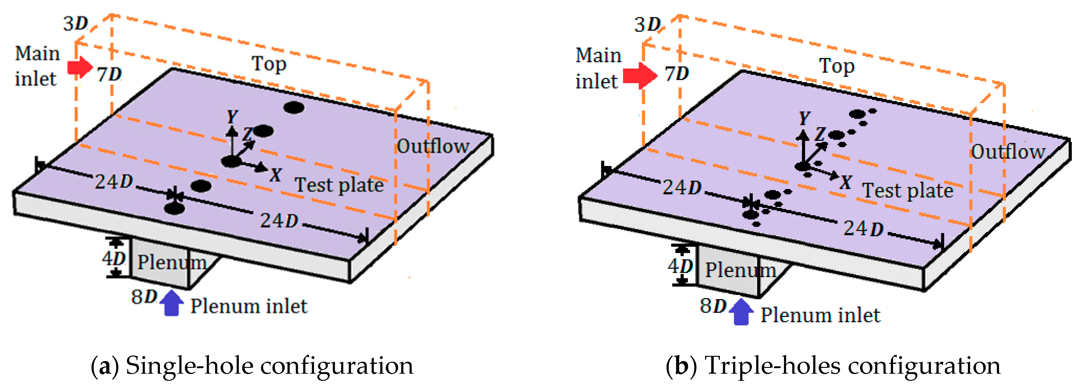
The geometry of the single-hole system in the test case was taken from Seo et al. [
13], whose experimental apparatus consisted of a row of five cooling holes. Herein, a single-hole configuration was adopted to simplify the computational domain, and a periodic boundary condition was applied on the mesh sides to reduce the computational cost. The computational domains of the single- and triple-hole systems are delineated by the orange dashed lines in
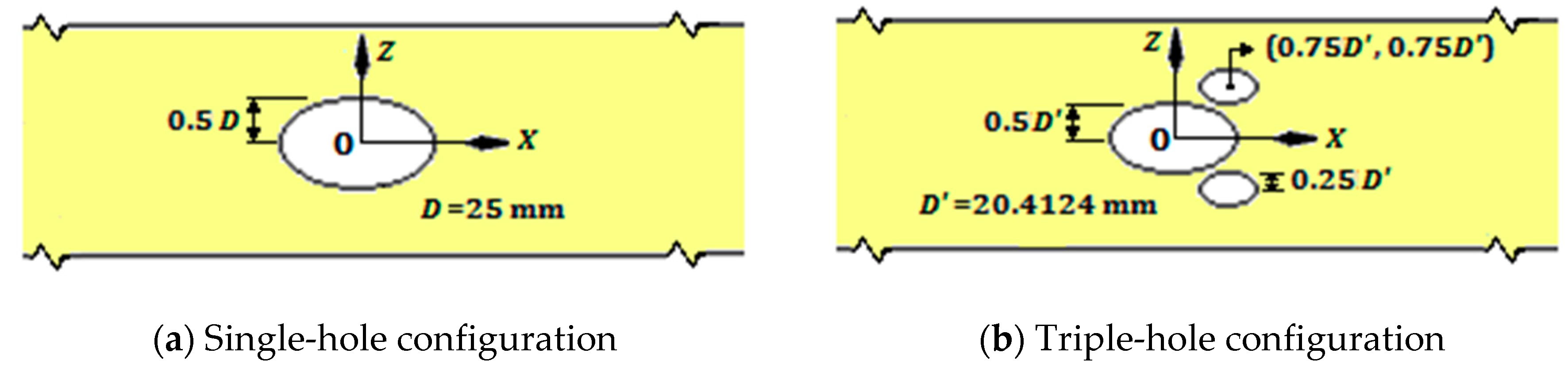
Figure 1, whereas a schematic of the cooling holes in each case is shown in
Figure 2. In the single-hole geometry (
Figure 2a), the hole diameter
D was 25 mm. The triple holes comprised two sister holes which are placed slightly downstream of the primary hole (
Figure 2b) as described in Ely et al. [
10]. In the triple-hole geometry, the hole diameters were calculated to match their total cross-sectional areas to the cross-sectional area of the single-hole. Thus, the primary hole diameter
D′ was 20.4124 mm, and the diameter of each sister hole was
D′/2 = 10.2062 mm. The hole length-to-diameter ratio (
L/D), injection angle (α), and pitch-to-hole diameter
(P/D) were set to 1.6, 35°, and 3.0, respectively. In addition, the holes were cylindrical, with no compound angles.
The boundary conditions in each computational domain are specified in
Table 1. The turbulence intensity of the mainstream flow was 0.2% at the main inlet (as reported experimentally [
13]), and the main flow velocity was 10 m/s. The temperatures of the main flow and coolant at the inlets were 313 and 293 K, respectively. Moreover, the boundary layer thickness at the cooling hole center is about
D.
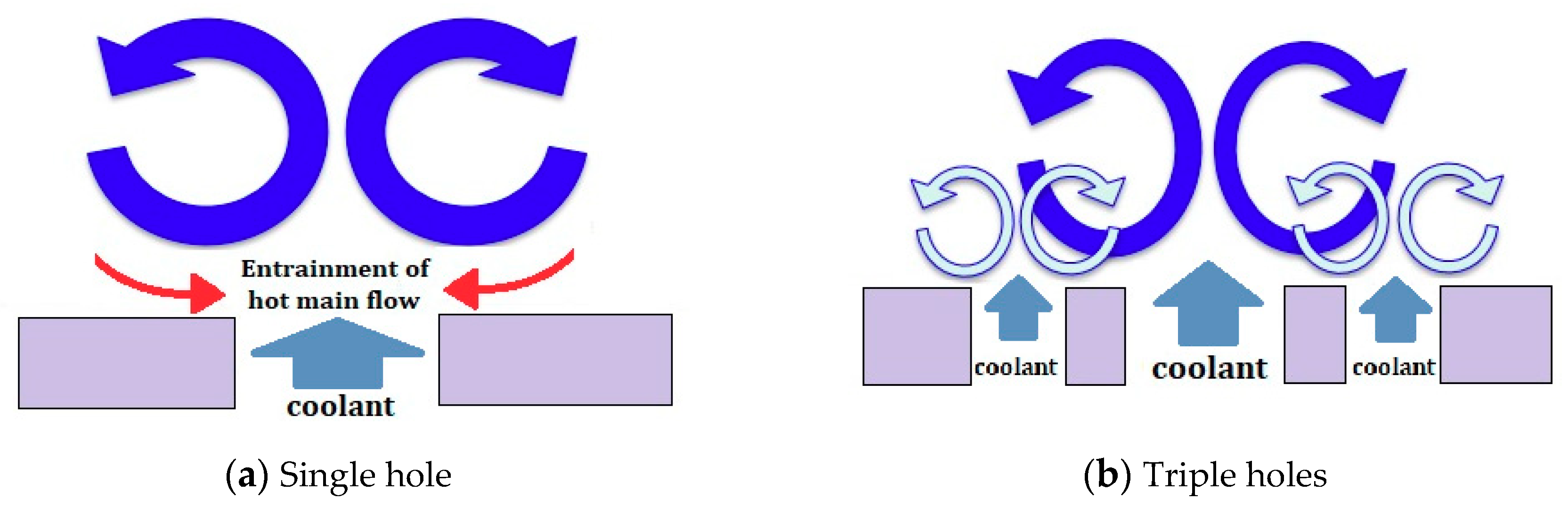
As is well-known, injecting the film-cooling jet induces a counter-rotating vortex pair (CRVP) in the system (see
Figure 3a). This vortex pair is sourced from the vortices generated in the boundary layer of the coolant tube wall and around the leading edge of the hole [
12,
14,
15]. Interactions between the jet and main flow cause the injected coolant to split into two directions, whereas the vortices generated in the coolant are stretched and turned. As the CRVP vortices draw closer together, their mutual induction increases, promoting coolant jet liftoff. The consequent strong entrainment of the hot main flow under the jet increases the adiabatic temperature on the test plate and decreases film-cooling effectiveness. Moreover, when two sister holes are placed slightly downstream of the primary hole (
Figure 2b), their jets generate an anti-CRVP, as illustrated in
Figure 3b. Therefore, film-cooling effectiveness is increased by establishing vortex interactions between the jets and by reducing the intensity of the main CRVP [
9,
10,
11,
12].
3. Validation of Numerical Methods
The CFD calculations were performed in ANSYS Fluent v.19.1 [
16], and the meshes were generated in Pointwise v.18.1 [
17]. The numerical simulations were executed in the LES using the Smagorinsky–Lilly model as the subgrid-scale model. The time step was set to 6.25 × 10
−6 s. Assuming the mainstream convected the hole diameter after 400 time steps, the simulations were carried out with the computational time step
[
18,
19]. Once the system had reached a statistical steady state, the statistics of the solution was collected in multiples of the period. In each time step, approximately 10 subiterations were executed to obtain well-resolved data [
20]. The LES runtime using 18 cores of an Intel Xeon Gold 6148 processor was 1–2 months in each case.
The fluid was assumed as Newtonian and incompressible and had temperature-dependent variable properties. The compressibility effect was negligible because the main flow velocity was 10 m/s (Mach 0.029) and the jet injection velocities were 5 and 10 m/s at
M = 0.5 and
M = 1.0, respectively; that is, both velocities were far below Mach 0.3 [
21]. The governing equations of the CFD simulations are the continuity and momentum equations. The filtered Navier–Stokes equations in the LES approach are given by [
22]
and
where
τij, the subgrid-scale turbulent stress, needs modeling using the Boussinesq hypothesis like RANS models as
where
μt is the turbulent viscosity on the subgrid scale. In the Smagorinsky–Lilly model, the turbulent viscosity is modeled as [
18]
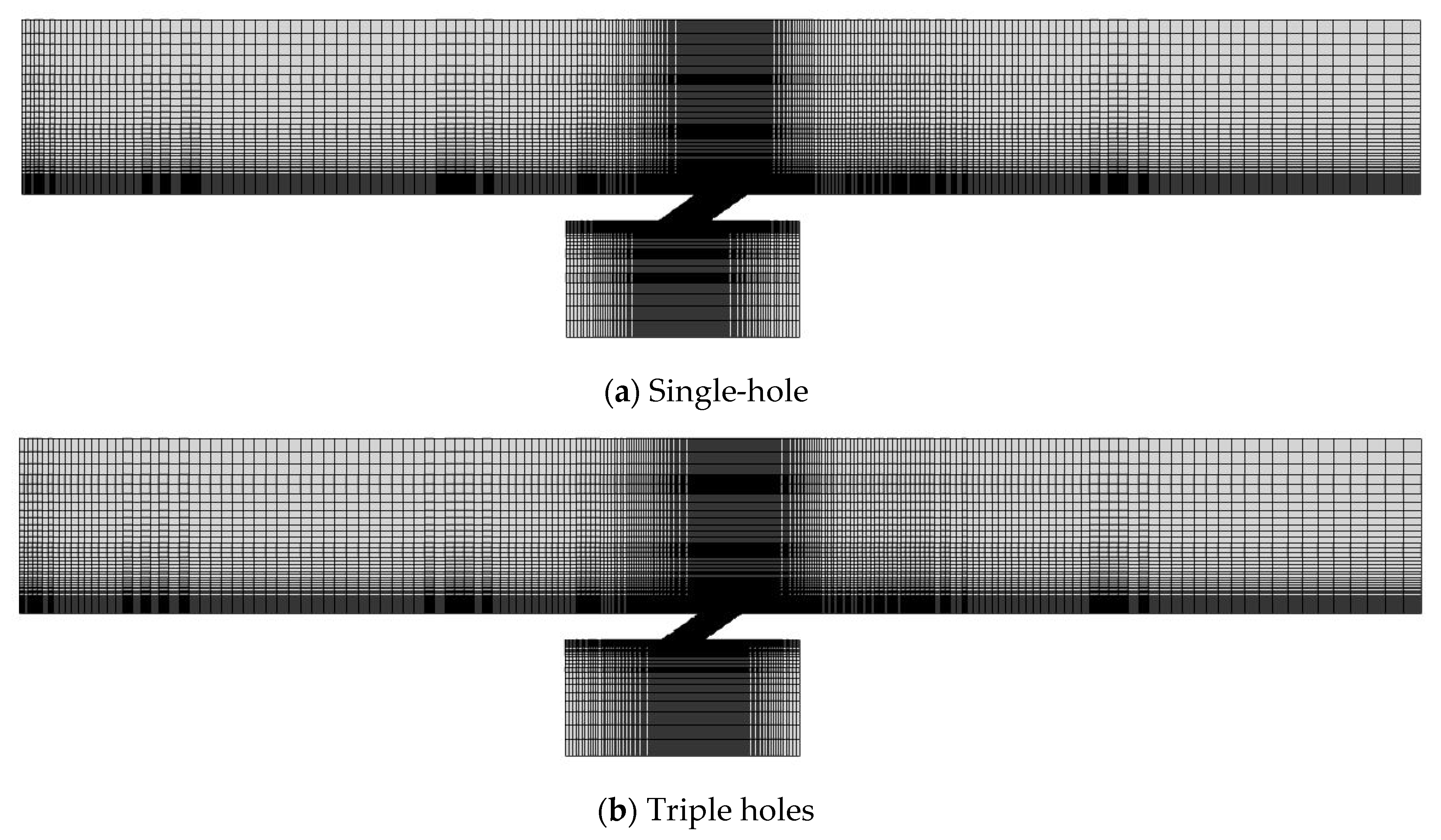
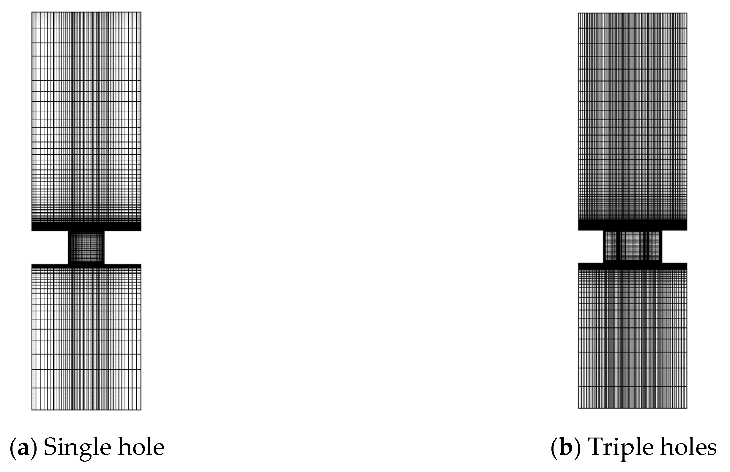
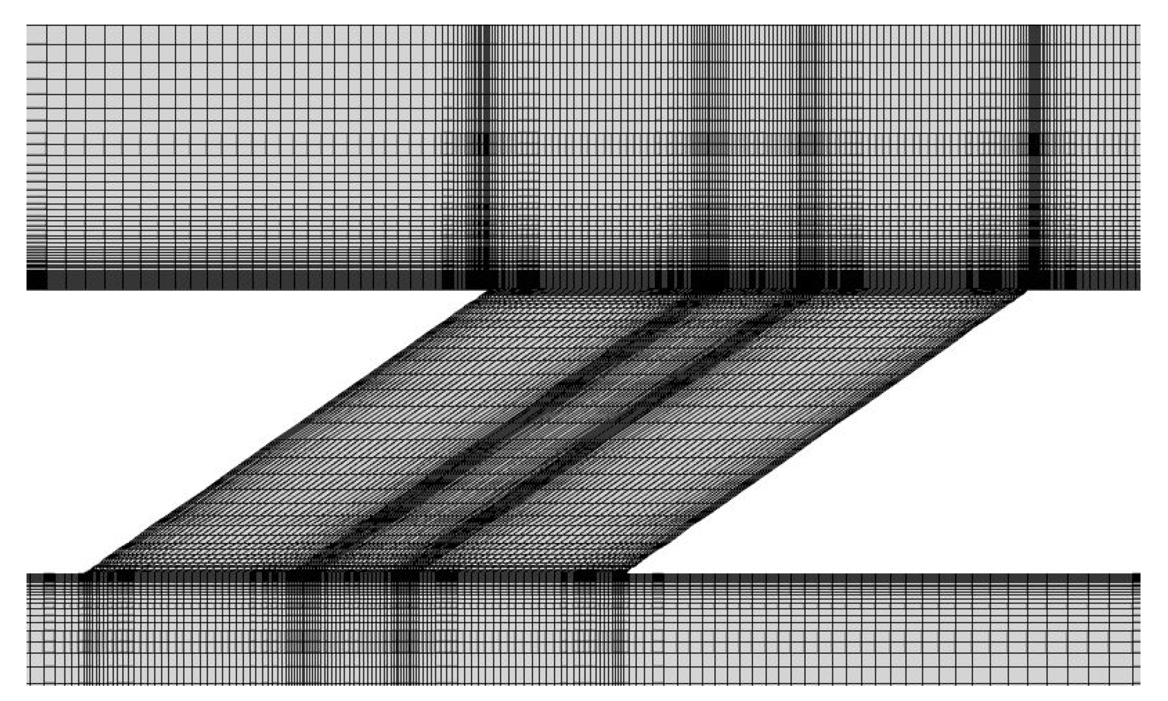
Figure 4 and
Figure 5 show the meshes of the single- and triple-hole systems in the
xy and
yz planes, respectively. The computational domains of the systems were composed of 2.04 (single-hole) and 2.69 (triple-hole) million hexahedron cells.
Figure 6 shows a close-up of the mesh near the hole, where P2 and P1 are the static pressures at the inlet and outlet of the hole, respectively, as mentioned earlier.
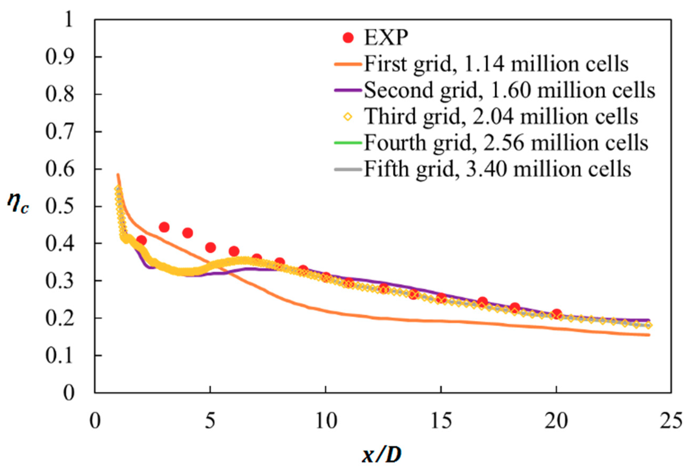
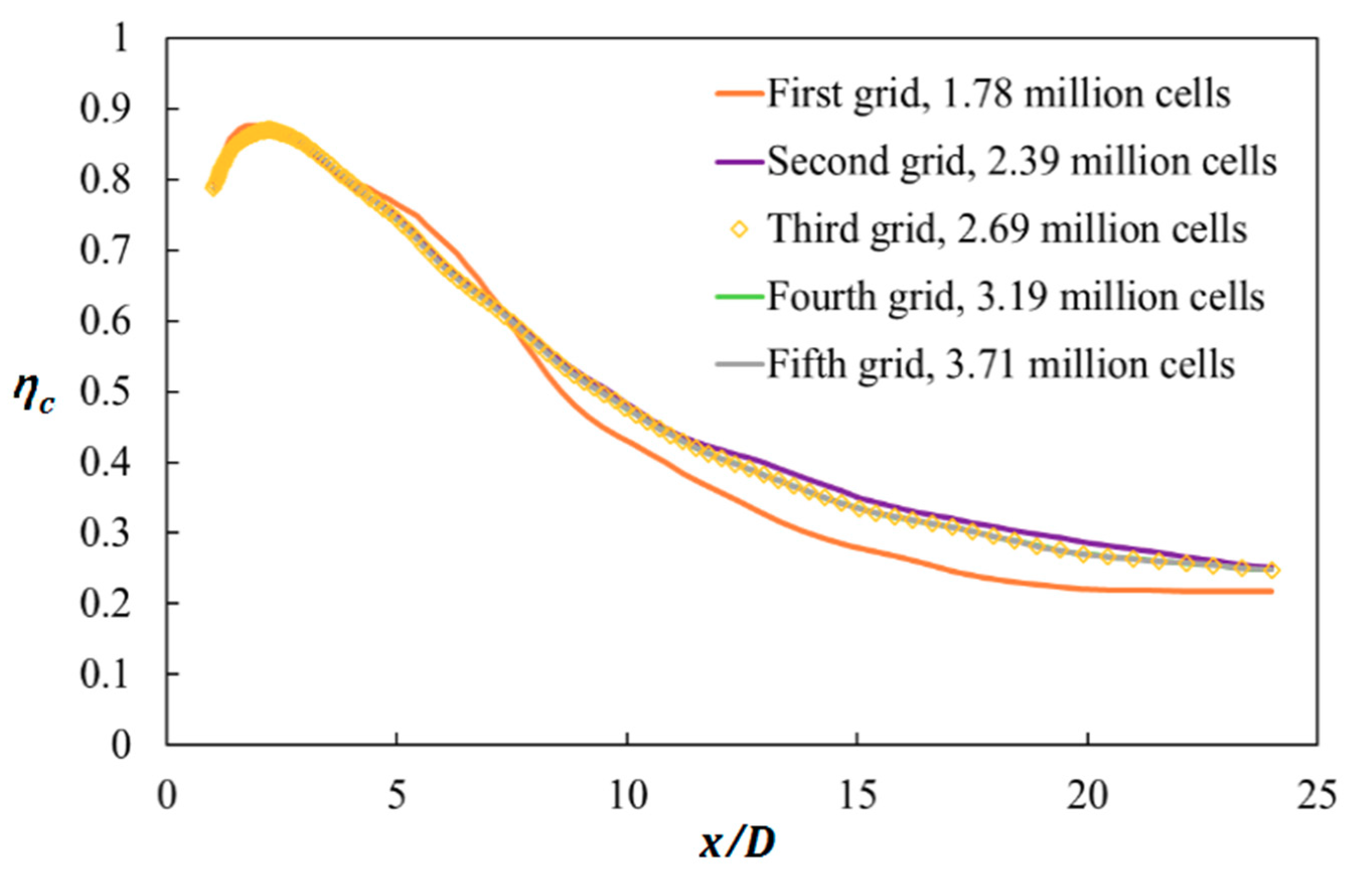
Figure 7 and
Figure 8 show the results of the grid sensitivity tests in each system at a blowing ratio of 0.5, with the grid descriptions given in
Table 2 and
Table 3. The results were obtained using the Smagorinsky–Lilly model in LES, and the tests were performed on five different grids. In the single-hole system, the effectiveness value along the centerline (
z = 0,
y = 0) on the third grid almost matched those of the finer fourth and fifth grids.
Therefore, the adiabatic film-cooling effectiveness in the single-hole system was evaluated on the 2.04 million-cell grid. In the triple-hole system, the third grid with 2.69 million cells again showed almost the same centerline effectiveness as the fourth and fifth grids. Therefore, the 2.69 million-cell grid was selected for modeling the film-cooling effectiveness in the triple-hole system.
4. Results and Discussion
4.1. Centerline and Spanwise-Averaged Film Cooling Effectiveness
Figure 9 shows the centerline and spanwise-averaged effectiveness values in the single- and triple-hole systems at
M = 0.5 and 1.0. The centerline effectiveness decreased as the main flow traveled downstream. This degradation is attributable to the turbulence generation and rapid mixing between the main flow and jet, which increases the test plate temperature. For the same total cross-sectional hole area and same amount of total cooling air, the triple holes improved the centerline and spanwise-averaged effectiveness values, respectively, by approximately 36% and 45% over the single-hole configuration at
M = 0.5 and approximately 250% and 345% at
M = 1.0. In
Figure 9a–d, the LES-predicted centerline film-cooling effectiveness in the single-hole system showed a good match to the experimental data by Seo et al. [
13], whereas the LES model under-predicted the triple-hole, spanwise-averaged effectiveness experimental data by Cao et al. [
22] because the data were measured for
L/D = 10. Thus, compared to lower
L/D cases, higher
L/D values of the hole increase the adiabatic film-cooling effectiveness under the same operating condition as the coolant velocity at the hole exit becomes more uniform [
13].
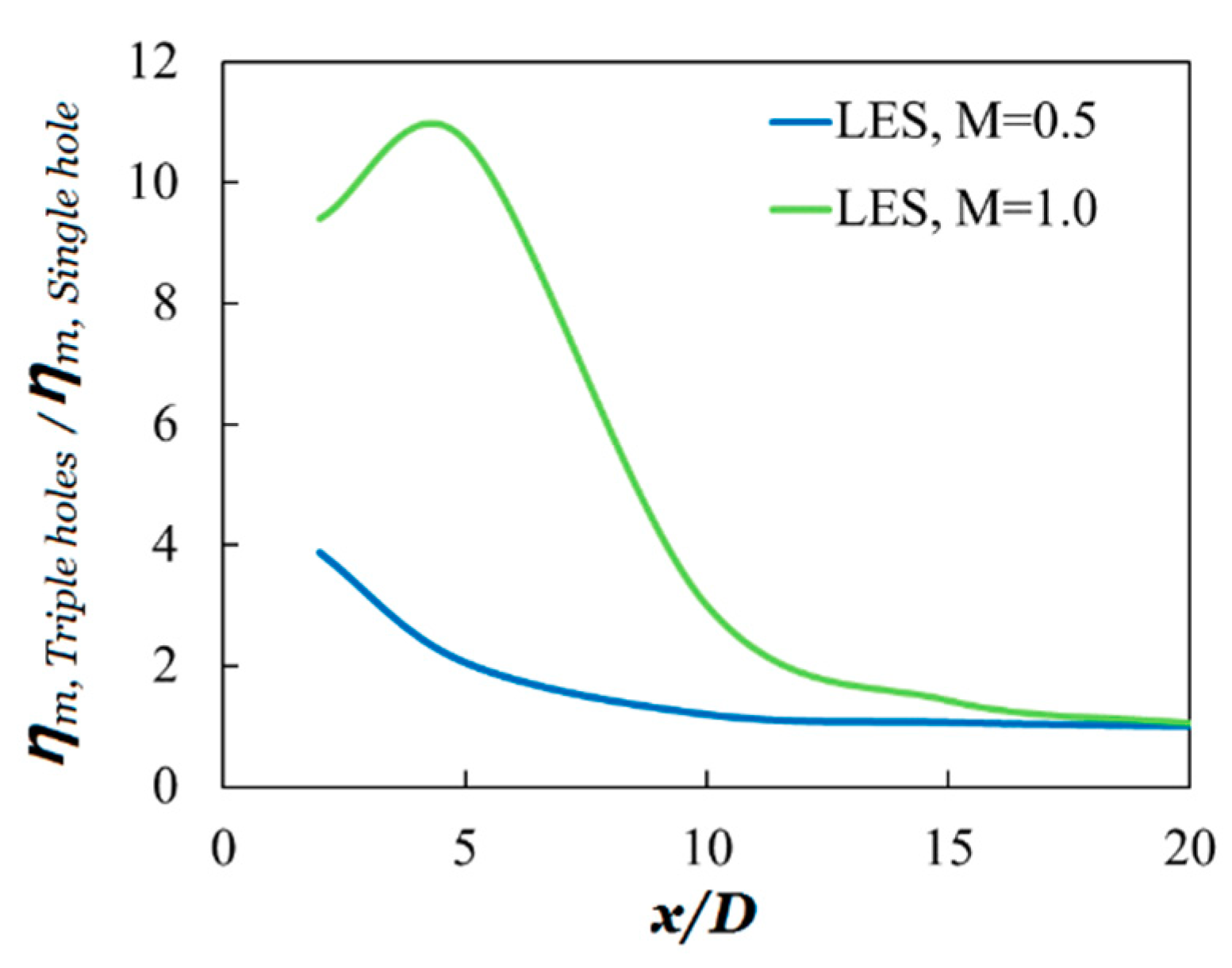
The ratios of the spanwise-averaged effectiveness values in the triple-hole system to those in the single-hole system as functions of
x/D for
M = 0.5 and 1.0 are plotted in
Figure 10. Note that increasing the blowing ratio improves the ratio of the spanwise-averaged effectiveness. This indicates that under high blowing ratios, configuring the main hole and two sister holes is more effective for film cooling than using an ordinary single hole mainly because the jet trajectory in the single-hole system is mostly governed by the jet liftoff at a high blowing ratio of
M = 1.0. The result is very low adiabatic film-cooling effectiveness, as indicated in
Figure 9c,d, and very high ratios of the spanwise-averaged effectiveness values, as shown in
Figure 10. The maximum value of the ratio at
M = 1.0 is observed around at
x/D = 4 since the minimum value of the spanwise-averaged effectiveness in the single-hole system is shown around at
x/D = 4 due to the jet lift off, as shown in
Figure 9d.
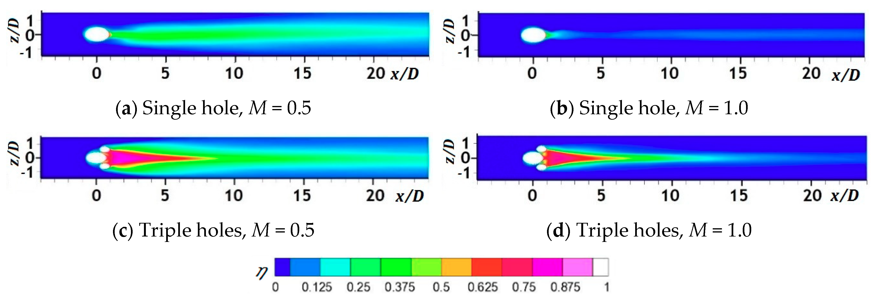
4.2. Contours of Film Cooling Effectiveness and Dimensionless Temperature
Figure 11 presents top views of the time-averaged film-cooling effectiveness contours on the test plate in each hole system. The additional sister holes largely increased the amount of coolant in contact with the test plate, which boosts film-cooling effectiveness. Moreover, the spread of the coolant in the spanwise direction in the triple-hole system was much larger than that in the single-hole configuration as the main CRVP weakens. Furthermore, lower film-cooling effectiveness was predicted at
M of unity than at
M = 0.5 because of strong jet liftoff.
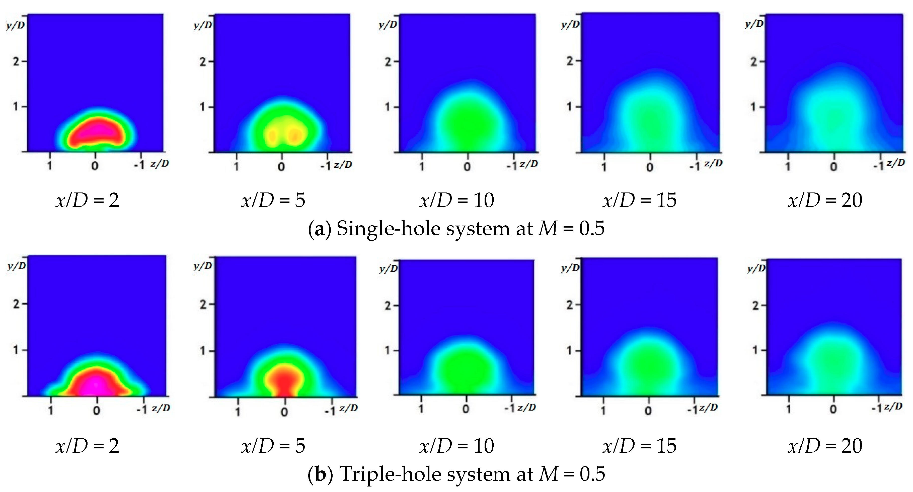
The cross-sectional views of the dimensionless mean temperature contours at
x/D = 2, 5, 10, 15, and 20 in the two systems are illustrated in
Figure 12. Initially, the dimensionless temperature near the test plate was higher in the triple-hole system than in the single-hole configuration, which increased film-cooling effectiveness on the test plate. As the main flow went downstream, the dimensionless temperatures near the test plate in the triple-hole system became similar to those in the single-hole system, leading to almost identical film-cooling effectiveness in the range of
x/D > 15 (
Figure 8 and
Figure 9) because of intensive mixing between the mainstream flow and coolant jet.
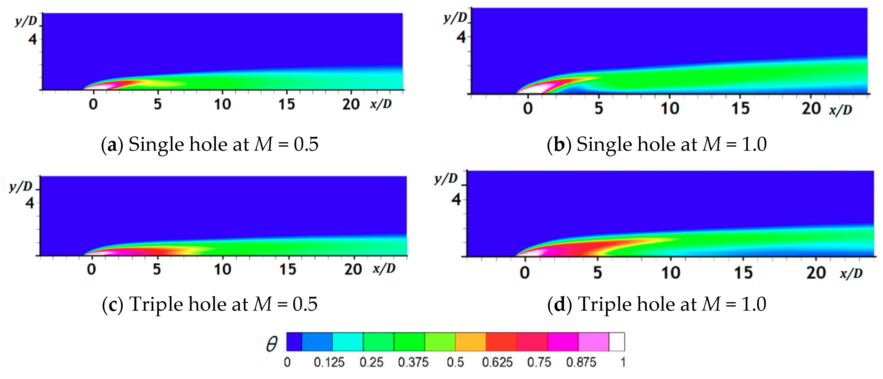
Figure 13 shows the central cross-sectional contours of the dimensionless mean temperatures in the
z = 0 plane for both hole systems. The entrainment of the main flow under the cooling jet in the triple-hole system was noticeably weaker than that in the single-hole system. Many researchers have argued that the jet lifted off because of the high momentum of the coolant and reattached downstream to the plate at a high blowing ratio [
2,
22,
23]. However, as illustrated in
Figure 13b, the dispersion of the coolant jet increases without reattachment with the test plate as the flow goes downstream after the jet liftoff, followed by the entrainment of the main flow under the jet. In addition, the dimensionless temperature near the test plate in the near-hole region in the triple-hole system was much higher than that in the single-hole configuration as vortex interactions between the jets were established, thereby reducing the intensity of the main CRVP at
M = 0.5 and 1.0 and increasing film-cooling effectiveness on the test plate.
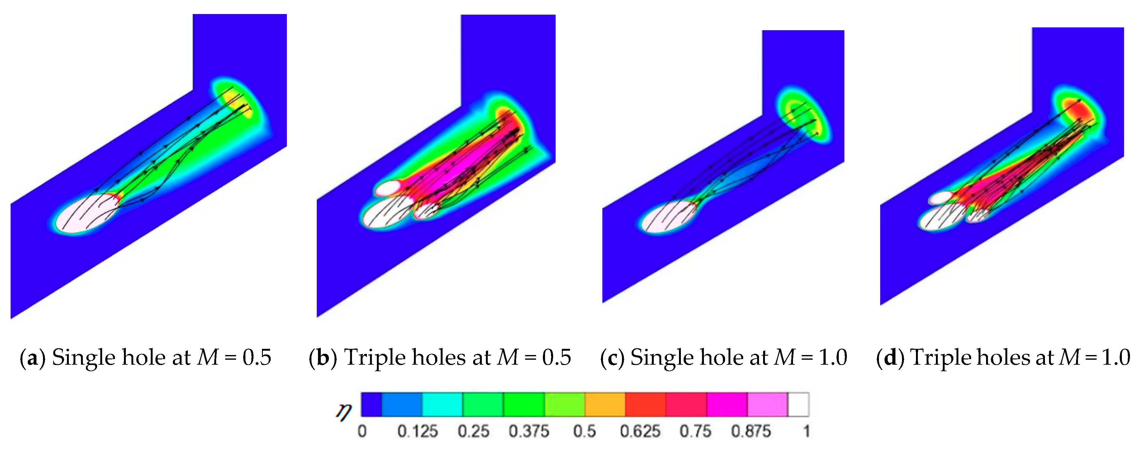
Figure 14 illustrates the streamlines of cooling jets to a cross-sectional plane at
x/D = 5 and film-cooling effectiveness on the test plate in the single- and triple-hole systems at
M = 0.5 and unity. Unlike in a single hole, more streamlines of the coolant head to the region near the test plate in the
x/D = 5 plane appeared in the triple-hole system, with these streamlines more dispersed, which resulted in higher adiabatic film-cooling effectiveness on the plate given that most streamlines from the sister holes have converged to the centerline. At
M = 1.0, the strong jet liftoff caused the streamlines to cover smaller regions laterally in the
x/D = 5 plane even in the triple-hole system.
4.3. Contours of x-Vorticity and Mean Velocity Vectors
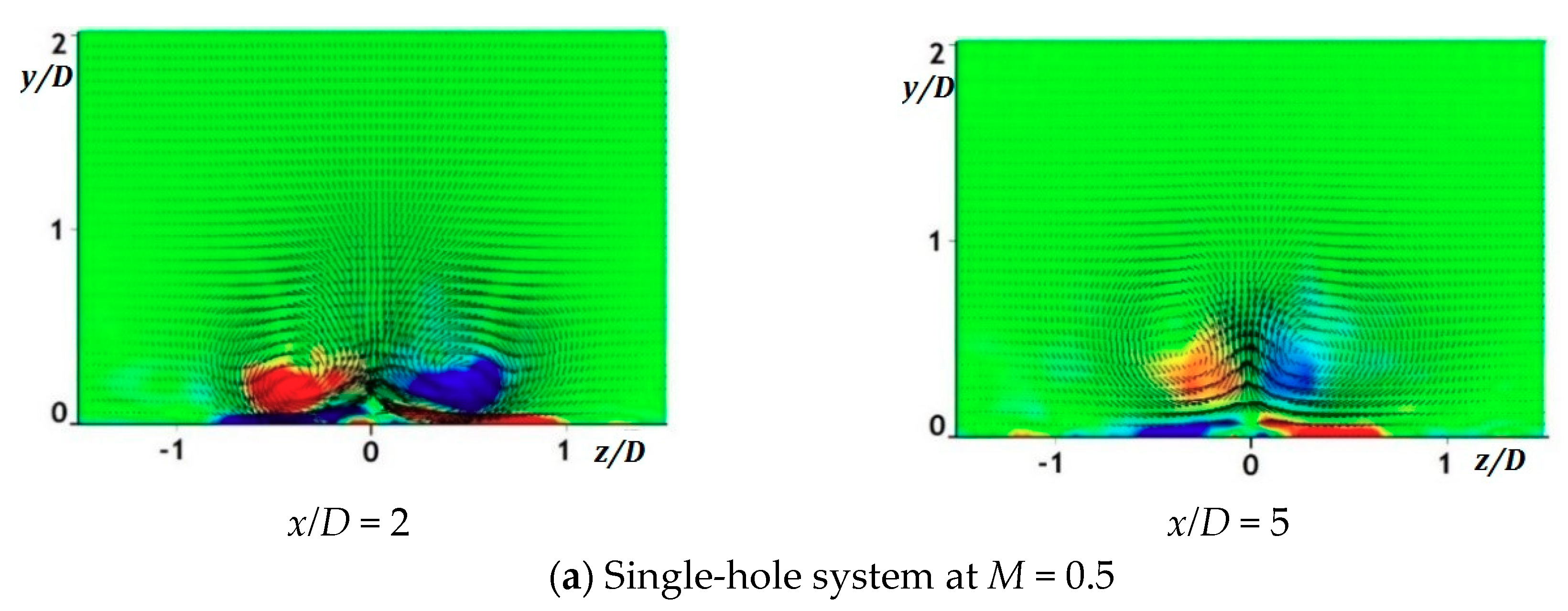
Figure 15 shows the cross-sectional contours of the mean
x-vorticity at the
x/D = 2 and
x/D = 5 planes in the single- and triple-hole systems at
M = 0.5 and unity. The mean velocity vectors are superimposed on the contours. As shown in
Figure 15b,d of the triple-hole system, distinct anti-CRVPs were found from the sister holes around the
x/D = ±0.5 and
y/D = 0.2 regions in the
x/D = 2 plane. The anti-CRVPs weakened the main CRVP and reduced the main jet liftoff, thereby reducing the entrainment of the hot mainstream gas under the coolant and increasing the dimensionless mean temperature and film-cooling effectiveness, as illustrated in
Figure 11 and
Figure 13. However, the intensity of the anti-CRVPs became very small in the
x/D = 5 plane because the anti-CRVP from the sister holes was not as strong as the main CRVP. In the triple-hole system, the upward velocity vectors around the line of
z/D = 0 were less concentrated than those in the single-hole system. Thus, coolant liftoff was weakened by the generated anti-CRVPs. At
M = 1.0, the positions of the core for the CRVPs were higher than those at
M = 0.5 because of the strong jet liftoff generated.
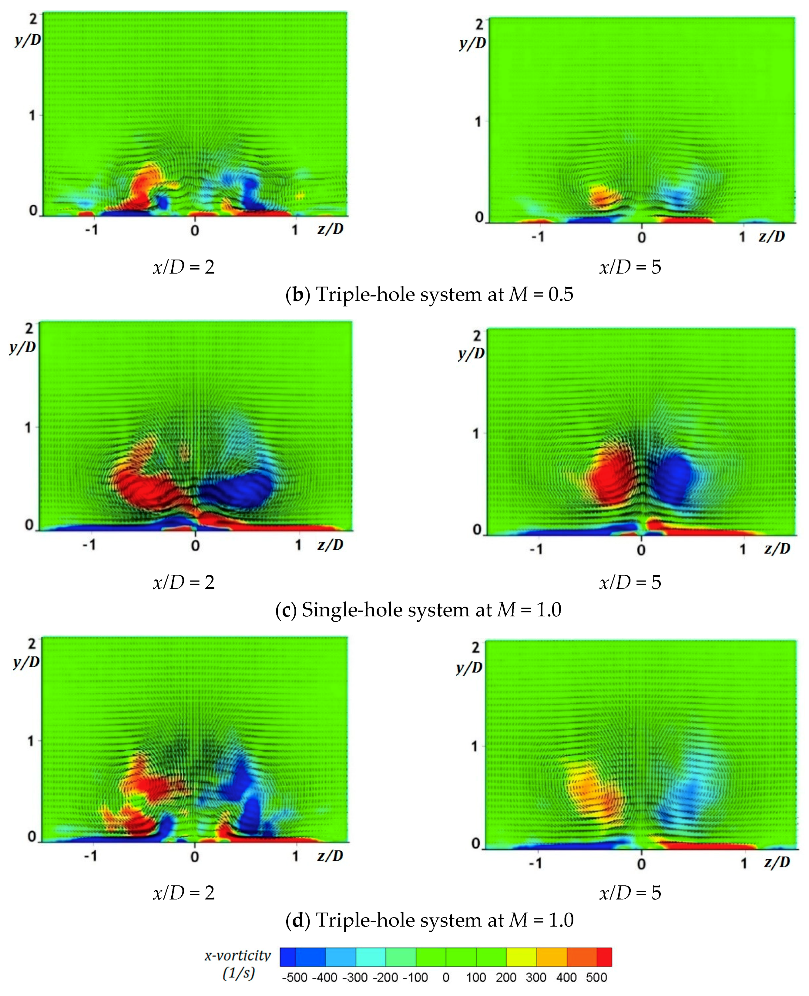
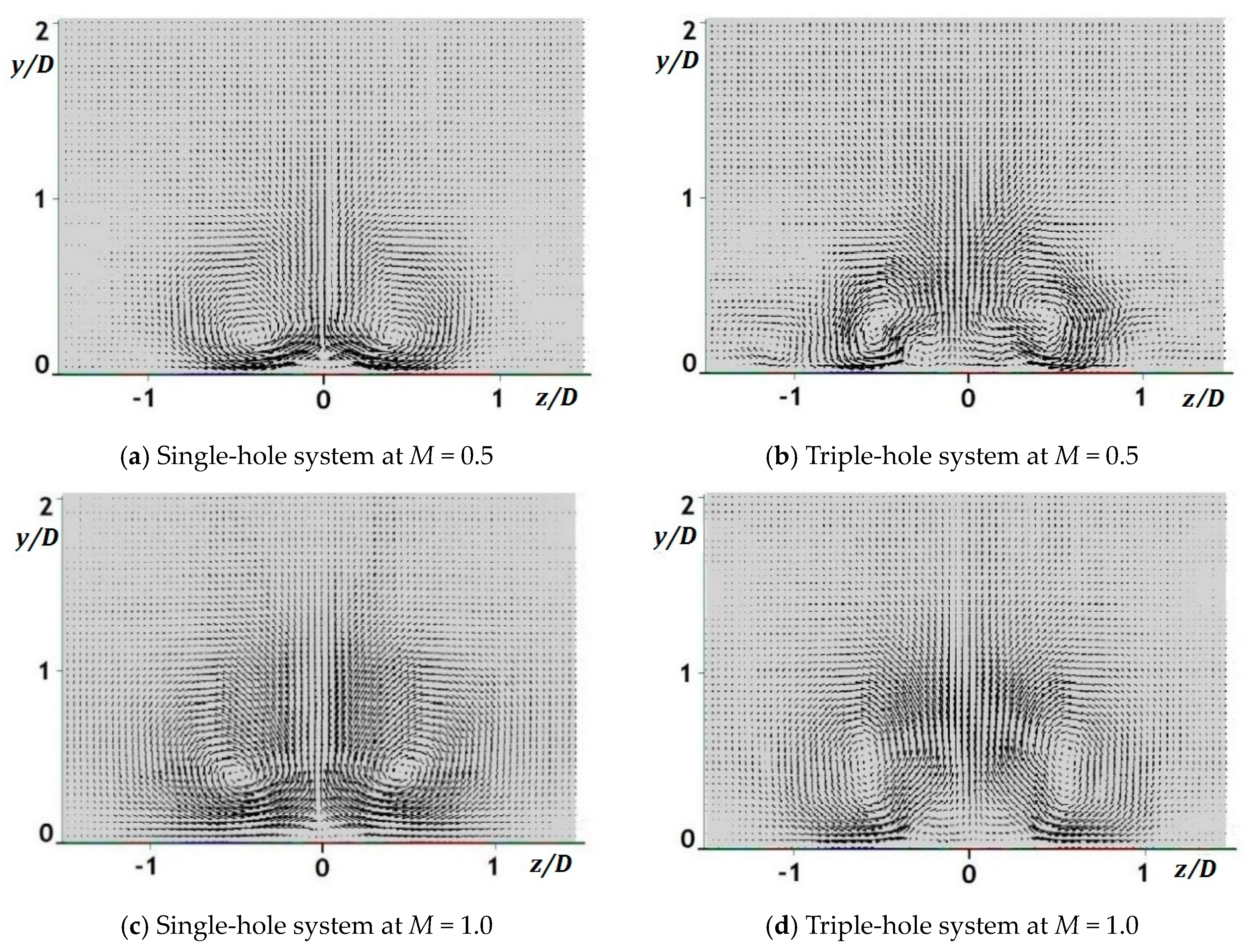
Figure 16 shows the cross-sectional velocity vectors of POD Mode 1 at
x/
D = 2 in the two-hole systems at M = 0.5 and unity. The POD was introduced by Dr. John Lumley in 1967 in order to decompose a random velocity vector field of turbulence into a set of portions of the total kinetic energy [
24,
25]. On the basis of the figure, CRVP was most distinct in the velocity vector field at
x/D = 2.
Figure 17 illustrates the portion of the total kinetic energy at
x/D = 2 for Modes 1, 2, 3, and 4 in the single- and triple-hole systems at
M = 0.5 and
M = 1.0, which showed Mode 1 as the most dominant. At
M = 0.5, POD Mode 1 contributed to about 60% and 36% of the total kinetic energy in the single- and triple-hole systems, respectively, which means that CRVP was dominant for both, although relative to the former, the portion of the kinetic energy in the latter system was largely decreased by about 40% because of a weakened main CRVP by anti-CRVPs from the two sister holes. Similarly, at
M = 1.0, POD Mode 1 contributed to about 71% and 49% of the total kinetic energy in the single- and triple-hole systems, respectively, indicating that the portion of the kinetic energy was decreased by nearly 30%. Indeed, it could be inferred that compared to that in the single-hole system, the kinetic energy of the CRVP in the triple-hole system was reduced by about 30–40%.
4.4. Root-Mean-Square Temperature Contours
Figure 18 illustrates the cross-sectional views of the root-mean-square (RMS) temperature contours at
x/D = 2, 5, 10, 15, and 20 for the mixing region between the mainstream flow and coolant in the single- and triple-hole systems. The mixing area was more expanded in the triple-hole system in the spanwise direction, especially in the near-hole region as
x/D = 2, because the weakened main CRVP allowed wider spreading and closer contact of the coolant jet with the test plate. Although no significant difference in the mixing intensity was observed in both hole systems, the
Trms in the
x/D = 2 plane reached maximum values of 6.25, 6.24, 6.08, and 5.19, as shown in
Figure 18a–d, respectively, which indicates a similar but slightly decreased mixing intensity in the triple-hole system relative to the single-hole system. This reduced mixing intensity is beneficial to film cooling because increased mixing between the coolant and mainstream flow consequently decreases film-cooling effectiveness [
22]. Nevertheless, it could be stated that in the triple-hole system, the effect of the sister holes on the jet trajectory contributes greatly to improve film-cooling effectiveness as compared to the effect of less mixing between the main flow and coolant.
4.5. Q-Criterion Iso-Surfaces
In the Q-criterion, Q is defined as the difference between the magnitudes of the rotation rate and strain rate, representing the dominance of the former over the latter [
26,
27,
28]. The instantaneous contours of a Q-criterion with iso-surfaces of level 80,000 at
M = 0.5 and unity are displayed in
Figure 19. Q-criterion contours in the single-hole system clearly showed various vortex structures, such as the CRVP, hairpin and jet shear layer vortices, and horseshoe vortex, whereas those in the triple-hole configuration had smaller hairpin and jet shear layer vortices and were not very distinguishable. These smaller and indistinct hairpin vortices represent the weakened CRVP as the hairpin vortex is closely related to the generation of the CRVP [
22]. A weakened CRVP positively affects the cooling performance on the plate because it increases film-cooling effectiveness on the test plate.
4.6. Cross-Sectional Contours of the Mean Velocity Magnitude in the Hole
Figure 20 shows the cross-sectional contours of the mean velocity magnitude in the hole measured around the hole exit (
y/D = −0.2). As mentioned earlier, the ratio of the delivery tube length to the hole diameter in the single-hole system was 1.6, whereas it was 1.8 and 3.6 for the main hole and sister holes in the triple-hole system, respectively, because the triple holes had the same total cross-sectional hole area as the single hole. Therefore, the mean velocity magnitude in the main hole is not uniform but has high- and low-momentum regions, whereas that in the sister holes shows more developed coolant flow. The cooling jet having a uniform velocity profile is advantageous to film-cooling performance because of less jet liftoff. Thus, it could be stated that relative to the single-hole system, the sister holes improve film-cooling effectiveness by the generation of the anti-CRVP, as well as higher
L/D ratios.
5. Conclusions
Film-cooling simulations of the single- and triple-hole systems on a flat plate were carried out in this paper at blowing ratios of M = 0.5 and unity by employing LES. On the basis of these simulations, when two sister holes which were placed slightly downstream the main hole, the coolant jets from the former generated an anti-CRVP, which increased film-cooling effectiveness. Thus, for the same total cross-sectional hole area and same amount of total cooling air, the triple-hole system increased the centerline and spanwise-averaged effectiveness values by approximately 36% and 45% at M = 0.5 and by approximately 250% and 345% at M = 1.0 as compared to that done by the single-hole configuration. Moreover, the ratios of the spanwise-averaged effectiveness values in the triple-hole system indicate that it is the more effective system for film cooling under a high blowing ratio.
Meanwhile, the time-averaged film-cooling effectiveness contours on the test plate and the cross-sectional views of the dimensionless mean temperature contours in the two hole systems showed that additional sister holes can increase the amount of coolant contacting with the test plate and boost film-cooling effectiveness. Specifically, the mean dimensionless temperature contours in the z/D = 0 plane showed that in the single-hole system at M of unity, as the cooling jet goes downstream, the jet gets dispersed without reattachment with the test plate, and the entrainment of the main flow under the jet is generated.
Furthermore, the cross-sectional mean x-vorticity contours in the triple-hole system showed that the generated anti-CRVPs weaken the main CRVP. The results of the POD analysis confirmed that the kinetic energy of the CRVP in the triple-hole system was reduced by about 30–40% relative to that in the single-hole system. Streamlines of the cooling jets to the cross-sectional plane at x/D = 5 also showed that most streamlines from the sister holes converge to the centerline. As with the Q-criterion contours in the triple-hole system, the hairpin and jet shear layer vortices were smaller and indistinguishable, unlike in the single-hole system.
Lastly, on the basis of the cross-sectional views of the RMS temperature contours, the effect of the sister holes on the cooling jet trajectory contributes significantly to the increase in film-cooling effectiveness, as compared to the effect of less mixing. Accordingly, the sister holes improve film-cooling effectiveness using higher L/D ratios.


