Article

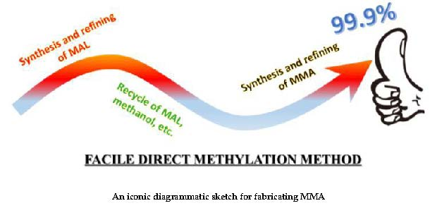
Design and Optimization of a Process for the Production of Methyl Methacrylate via Direct Methylation

1
Green Intelligence Environmental School, Yangtze Normal University, Chongqing 408003, China
2
Faculty of Materials and Energy, Southwest University, Chongqing 400715, China
3
College of Chemistry and Chemical Engineering, Yangtze Normal University, Chongqing 408003, China
4
State Key Joint Laboratory of Environment Simulation and Pollution Control, School of Environment, Tsinghua University, Beijing 100084, China
5
College of chemistry and bioengineering, Guilin University of Technology, Guilin 541004, China
*
Author to whom correspondence should be addressed.
Processes 2019, 7(6), 377; https://doi.org/10.3390/pr7060377
Submission received: 25 April 2019 / Revised: 31 May 2019 / Accepted: 6 June 2019 / Published: 18 June 2019
(This article belongs to the Section Chemical Processes and Systems)

Abstract

:
Methyl methacrylate (MMA) plays a vital role in national productions with broad application. Herein, the production of MMA is realized by the improved eco-friendly direct methylation method using Aspen Plus software. Three novel kinds of energy-saving measures were proposed in this study, including the recycle streams of an aqueous solution, methacrolein (MAL), and methanol, the deployment of double-effect distillation instead of a normal one, and the design of a promising heat-exchange network. Moreover, MMA with a purity of 99.9% is obtained via the design of a MAL absorber column with an optimal stage number of 11 and a facile chloroform recovery process by using the RadFrac model. Thus, the proposed green process with energy-conservation superiority is the vital clue for developing MMA, and provides a reference for the production of MMA-ramifications with excellent prospects.

Graphical Abstract

1. Introduction

Methyl methacrylate (MMA), an essential chemical raw material, has drawn growing interest in the fields of poly(methyl methacrylate) (PMMA), functional coatings, lubricant additives, ion exchange resins, construction materials, lighting equipment, etc., due to excellent transparency and weather resistance [1,2,3,4,5,6]. It is worth mentioning that the production of MMA needs to grow quickly and steadily due to the increasing demand for MMA in the world [7,8,9,10]. Thus, it is necessary to develop a green process for preparing MMA efficiently.
In fact, several processes for obtaining MMA have been developed up to now, including the C2-method (ethylene carbonylation, etc.) [11], C3-method (acetone cyanohydrin (ACH), etc.) [12], and C4-method (isobutylene direct methylation method (IDMM), methacrylonitrile process, etc.) [13,14], which are clearly seen in Figure 1. Based on the mentioned methods, lots of researchers have devoted efforts to exploring MMA production processes, notably including a separate process of a mixture of methyl methacrylate, methanol and water. For example, Wu et al. studied the optimization design and dynamic control of the simplified separation process for MMA by using a one-column flowsheet with a middle decanter, which can cut operating costs by 35.9% compared to the industrial three-column design. Large disturbances of the feed composition can be effectively controlled [15]. Chang et al. studied an alternative design for separating mixtures (including methyl methacrylate, methanol, and water) using a distillation column, a stripper and a decanter. Compared with the traditional design process, the operating cost of during this improved design significantly reduced to 25.9%. In addition, based on open/closed-loop sensitivity testing, the overall design turns out to ensures the product of MMA with a high degree of purification [16]. The azeotropic distillation and ionic liquid eco-environmental separation of methacrolein (MAL) was investigated by Yan et al. to obtain MMA, and results indicated that used green process had significant economic and green-degree advantages [14]. Compared with related reports, C4-IDMM has gradually been regarded as a promising green technique, due to the low-cost equipment, short reaction path, and sufficient raw materials, and so on [12,13,17], though there are no large-scale uses in industry. However, it is still a challenge to develop the production process of MMA based on C4-IDMM economically. The method used in our study is based on the improved direct methylation of isobutylene method proposed by the Asahi Kasei Corporation. There is no MAA step during this process, which effectively avoids side reactions such as MAA polymerization, simplifies the process flow, and reduces energy consumption, thereby greatly reducing operating costs and investment costs and making it more competitive.
Thus, the focus of this report is on the facile design of an MMA synthesis route by using a direct isobutylene methylation method to reduce the energy consumption. Moreover, ASPEN simulation software, an effective and common tool, is used for process simulation and data analysis at the same time.

2. Simulation and Experimental Methods

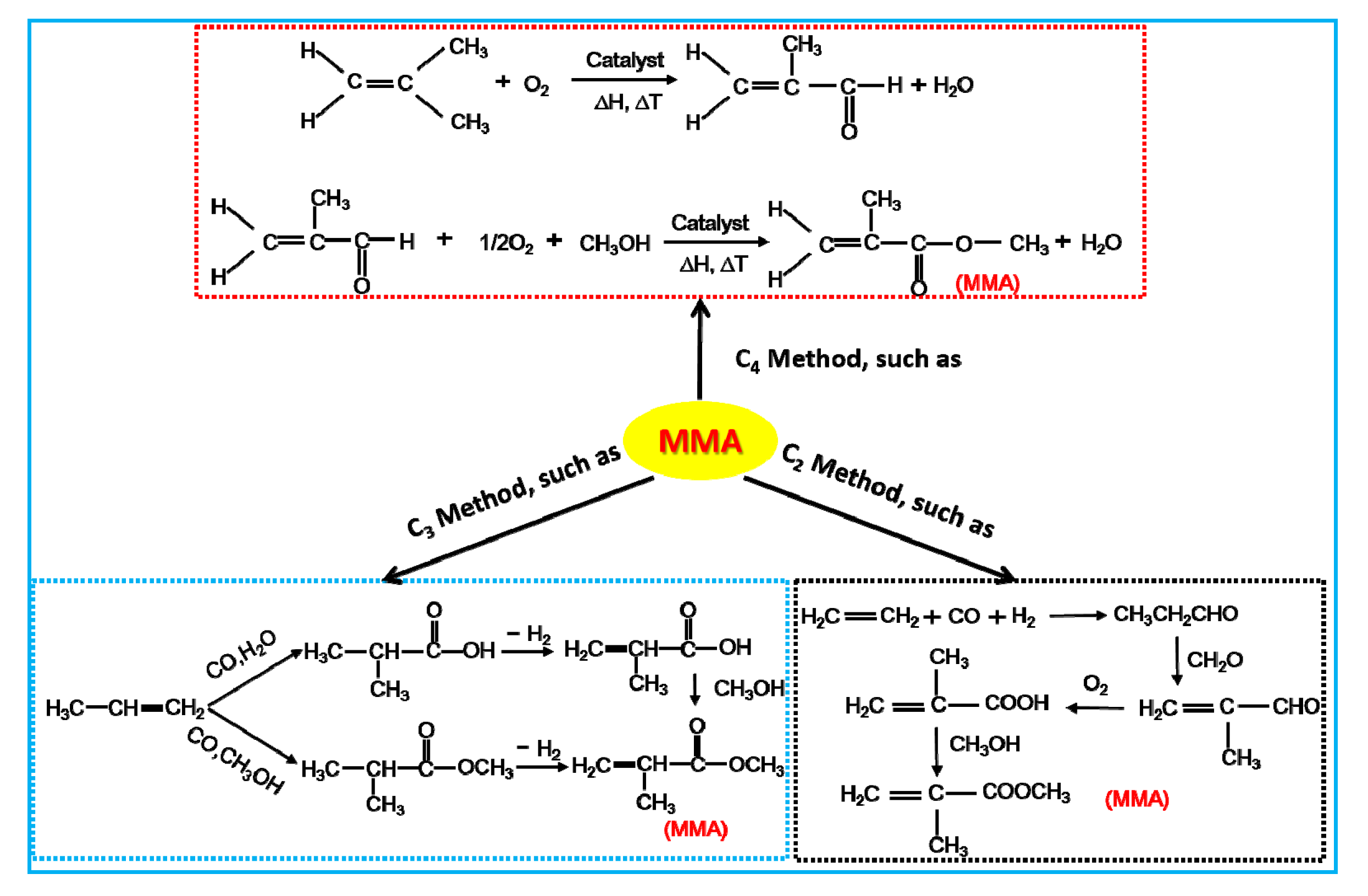
2.1. Main Reaction Equation

The production process-C4-IDMM of MMA in this study is based on the Asahi direct method, also called direct methylation as follows. Firstly, the oxidation of isobutylene (Aladdin Industrial Corporation, Shanghai, China) produces methylacrolein, which acts with air in the liquid phase. Then, the product of the previous step undergoes the one-step esterification oxidation reaction with excess methanol (Aladdin Industrial Corporation, Shanghai, China) to obtain MMA, where the catalyst is Pd (Aladdin Industrial Corporation, Shanghai, China), and the carrier is CaCO3 (Aladdin Industrial Corporation, Shanghai, China) or ZnO (Aladdin Industrial Corporation, Shanghai, China), and the activity and stability of the whole reaction is improved by adding metal elements of Pb, Bi or Zn, etc. [18,19]. The synthetic route is shown clearly in the following Equation (1):
Processes 07 00377 i001

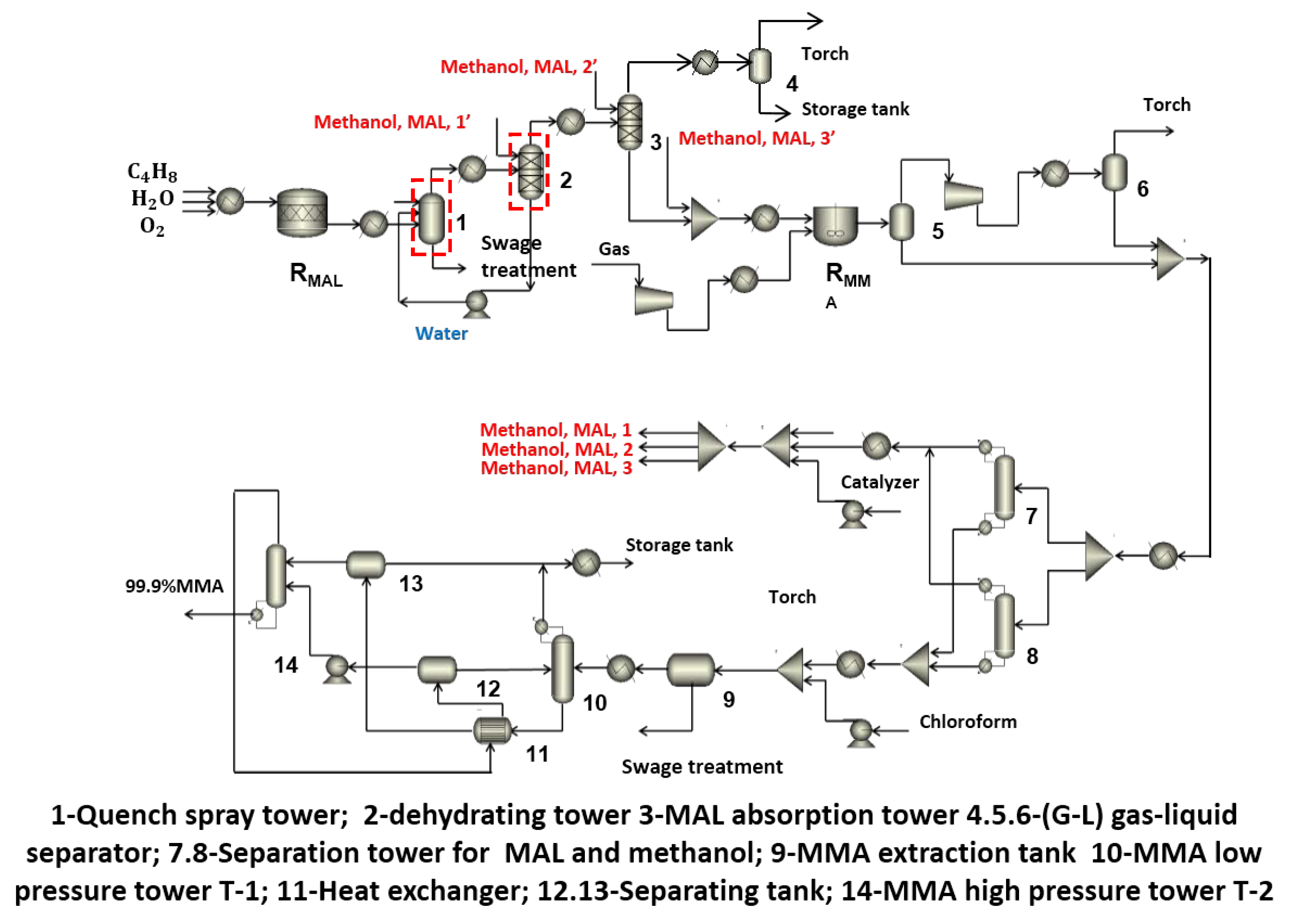
2.2. Whole Process Design

The process route for MMA based on direct methylation mainly includes an isobutylene oxidation unit, MMA synthesis and refining unit, and methanol recycling unit. The main process is shown in Figure 2. Practically speaking, using isobutylene as raw material, MAL is produced through a MAL synthesis reactor (RMAL) with H2O and O2. Mixed gases pass through the quenching spray tower (1), the dehydration tower (2), and the MAL absorption tower (3) to obtain MAL with high purity. Then, gas phases from the top of tower (3) undergo tail-gas treatment in separator (4) after methanol recovery, and a degasification process in separators (5) and (6). The liquid phases from the bottom top of tower (3) go into RMMA to produce an MMA solution with relative low purity. The methanol and MAL recovered from obtained MMA solution in separation towers (7) and (8) are recirculated to towers (1), (2), and (3). Then, after separation of MMA and water in the MMA extraction tank (9), the MMA organic phase goes into a double-effect rectification process with an MMA low pressure tower T-1 (10), heat-exchanger (11), separating tanks (12) and (13), and MMA high pressure tower T-2 (14) in the scrubbing towers, and then the MMA with high purity is finally obtained.

2.3. Process Simulation

2.3.1. Thermodynamic Method Determination

Aspen Plus software (Version 8.4, Aspen Technology, Inc., Bedford, MA, USA) contains lots of different physical methods selectively applied to various conditions and materials with diverse characteristics [20,21,22,23,24,25]. In this report, the raw materials are mainly isobutylene, methanol, and air, where the gas phase conforms to Henry’s Law of the ideal gas and the gas law, and the liquid phase belongs to a non-ideal system. Therefore, the universal functional activity coefficient (UNIFAC) thermodynamic calculation model is selected for the MAL refined synthesis process, which is used for tower (1) and (2) (with the dashed red boxes, in Figure 2). The non-random two-liquid Redlich-Kwong (NRTL-RK) thermodynamic calculation model is used for other processes, such as the double-effect rectification process. It is worth mentioning that the application of the two models for accurately simulating and analyzing the vapor-liquid equilibria (VLE) and liquid-liquid equilibria (LLE) properties of non-ideal solutions is feasible.

2.3.2. Process Design

The whole process of obtaining MMA includes two steps of MAL and MMA production and a synthetic refining section. During the oxidation reaction of isobutylene, the gas phase components in the reaction system mainly contain isobutylene and oxygen. The reaction temperature and operating pressure are 380 °C and 1 bar (1 bar = 0.1 MPa), respectively. Due to the oxidation reaction of isobutylene with Mo-Bi as the catalyst, which is an exothermic reaction, the volume ratio of water vapor:isobutylene:air = 6:6:88 [26], and the reactor is selected as a stoichiometry reactor (RStoic) with an isobutylene conversion and MAL selectivity of 97.31% and 92.34%, respectively [26]. In the MAL oxidative esterification reaction, the system contains MAL, methanol, air, and other components. The reaction temperature and operating pressure are controlled at 50 °C and 1 bar, respectively, and the reactor is an RStoic with MAL conversion and MMA selectivity of 98.8% and 85.9%, respectively [27]. A strict-distillation module can calculate the rectification, gas-liquid separation, absorption, extraction, and countercurrent double-effect rectification for all separation units.

2.3.3. Data Acquisition

During the simulation process, the substances contained in the physical property system are ordinary and can be directly retrieved from the Aspen Plus database. The relevant operating parameters in the chemical engineering process and the actual operating conditions data play important roles in determining the initial value of the simulation process.

3. Results and Discussion

3.1. Process Recycle Design

Based on the need to save energy-saving, three kinds of recycle streams are used in the production process of MMA. Specifically, one is the water stream, as shown in Figure 2, where the water used in the quench spray tower goes into the dehydrating tower, and the extruded water goes back to the quench spray tower by a centrifugal pump, realizing water recycling. In addition, the energy-saving of one specific process largely depends on the full use of raw materials or a key intermediate product in this study. We focus on MAL and methanol. Clearly, the two streams from two separation towers for MAL and methanol (7 and 8, in Figure 2) are re-used back in the dehydrating tower (methanol, MAL, 1’), MAL absorption tower (methanol, MAL, 2’), and following mixer (methanol, MAL, 3’), contributing to increasing their utilization and reducing the consumption and the loss of intermediate products, further increasing the yield.

3.2. Design of a Highly Efficient MAL Absorption Column

How to absorb the MAL obtained from isobutylene is a key to preparing the MMA. Methanol regarded as an excellent absorbent for MMA, not only realizes the separate effect, but also does not introduce novel impurities, due to methanol being a reactant and absorbent, respectively. Thus, there is no need for subsequent steps such as rectification and purification for MAL, shortening the process and reducing the energy and economic investment simultaneously. Additionally, the desired MAL can be separated from a liquid by countercurrent contact with methanol in a MAL absorber column with a pressure of 0.2 MPa and an operating temperature of 34.2 °C. The absorption rate of MAL by the MAL absorption tower is 99.32% in this study.

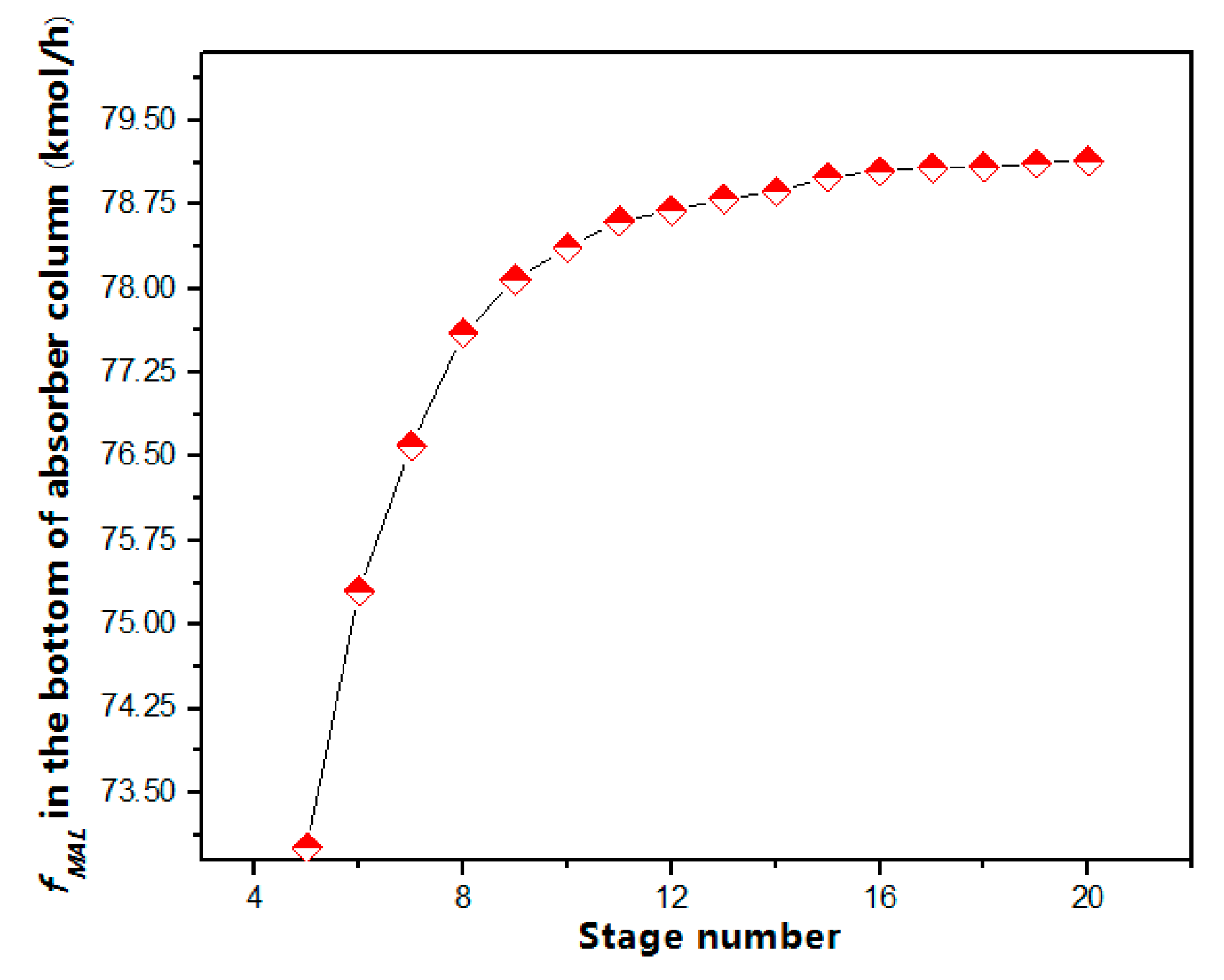
3.2.1. MAL Absorber Column Stage

The MAL absorber column stage largely depends on the absorptive amount of MAL. The sensitivity of the absorption is analyzed using Aspen Plus’ RadFrac model. The stage of the absorber column ranged from 5 to 20. Figure 3 shows the flow rate of MAL (fMAL) at the bottom of the column as a function of stage number. Clearly, the “fMAL” increases sharply as the stage increasing from 5 to 11, where it is close to the peak value. But, the “fMAL” almost remains stable as the stage number continues to rise. As is well known, the higher the stage number, the higher the column height, indicating the higher pressure drop [14]. Therefore, the column stage number of 11 should be preferred after considering the equipment fee and high “fMAL” comprehensively.

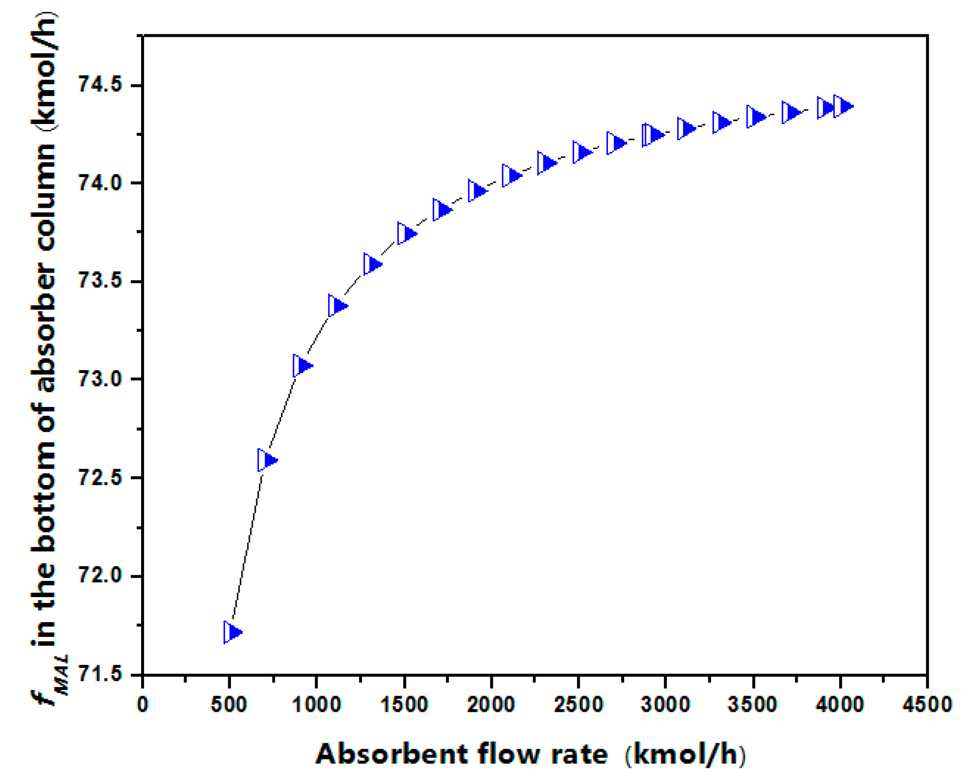
3.2.2. Methanol Absorbent Flow Rate

The Aspen Plus’s RadFrac model is also used to determine the methanol flow rate. The relationship between of the “fMAL” and methanol flow rate is shown in Figure 4. Clearly, “fMAL” increases with the flow rate of the methanol solvent. However, the growth rate of “fMAL” decreases gradually and nearly reaches to 0 when the methanol flow rate is larger than 3000 kmol/h, which indicates that excess absorbents are not necessary, in addition to reasons of higher cost and energy consumption. Thus, the preferred methanol flow rate is ca. 3000 kmol/h for the MAL absorption process.

3.3. Controllable Design for MMA with High Purity

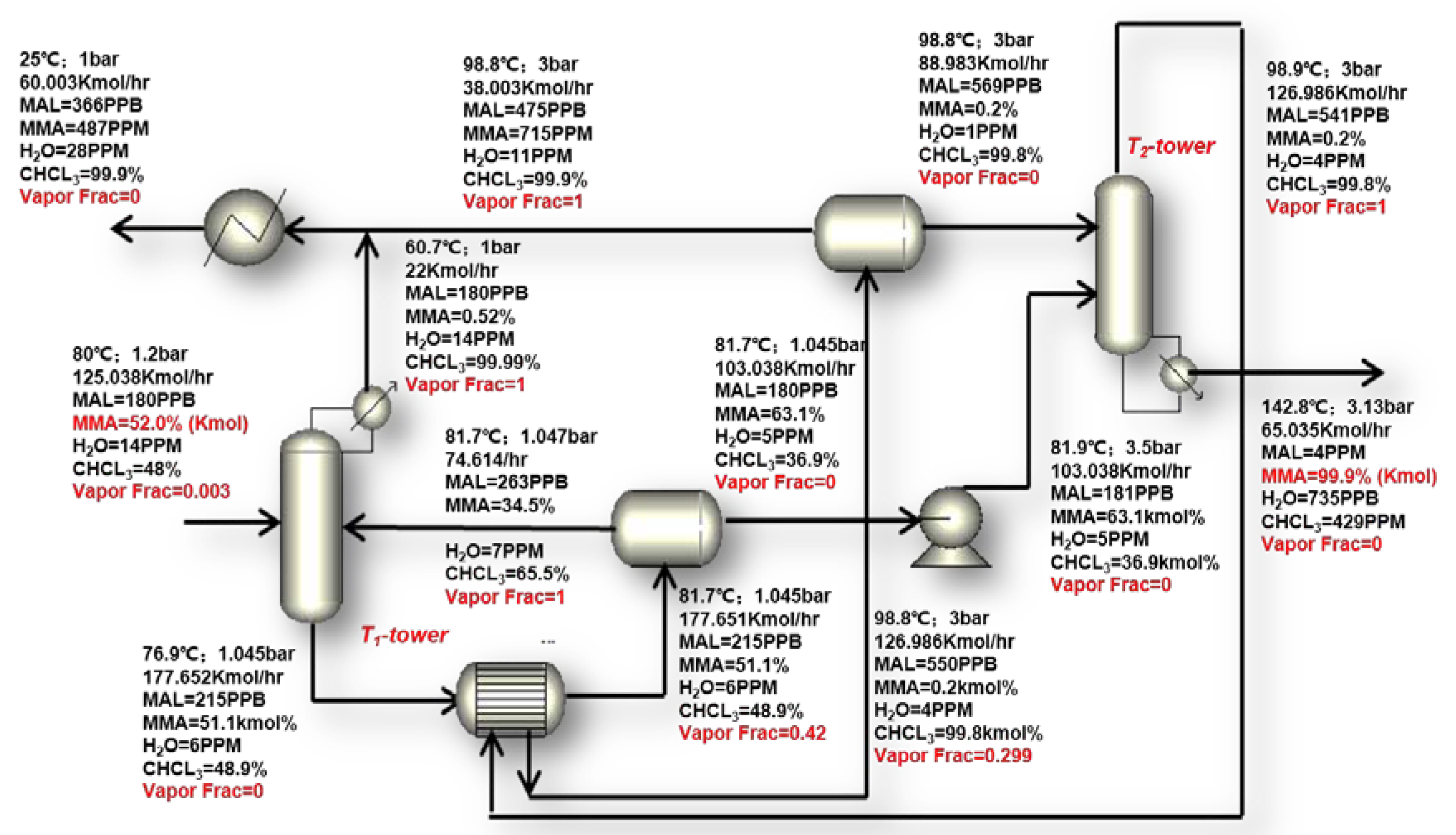
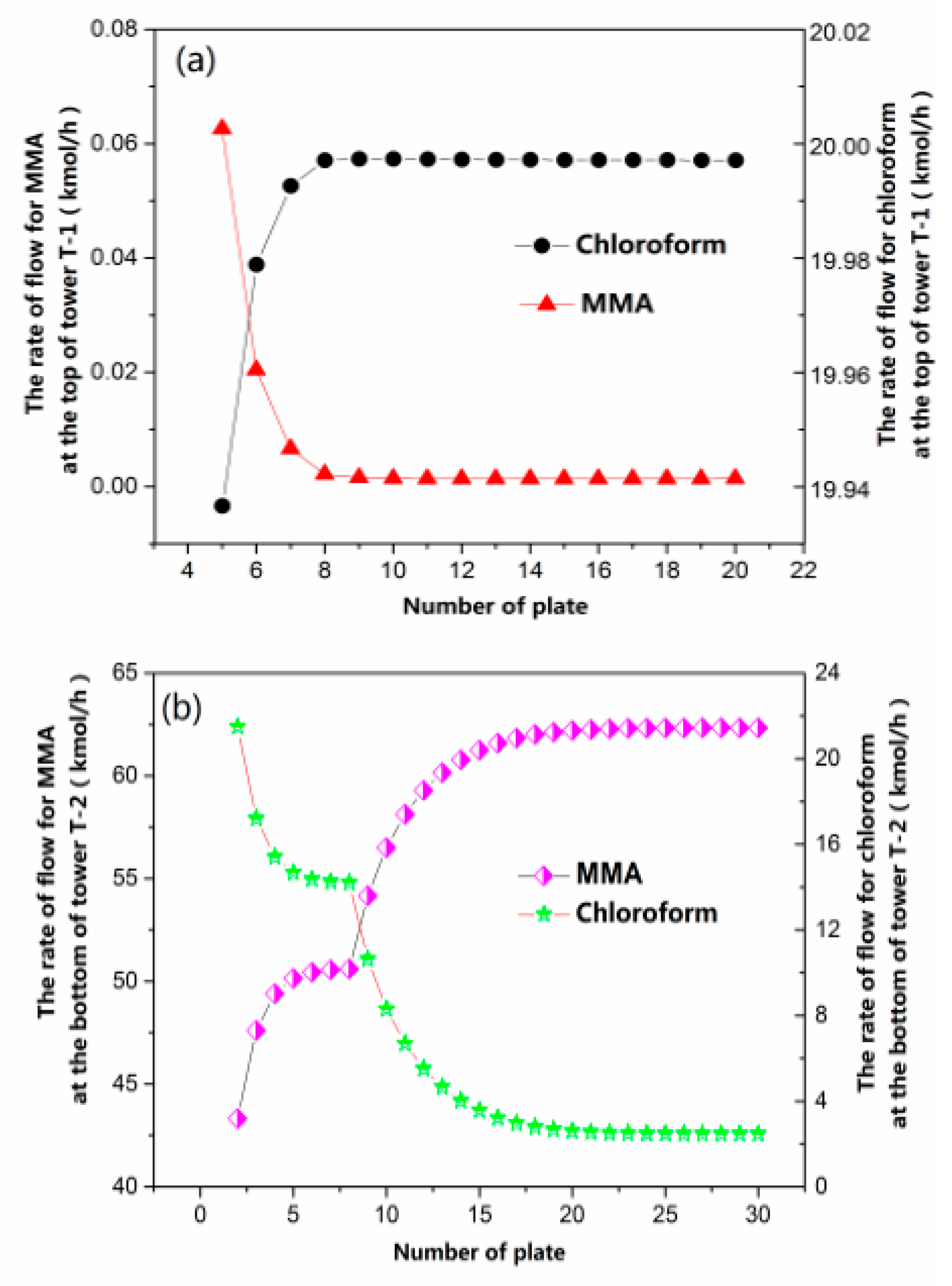
3.3.1. Double-Effect Distillation Design

The purity of MMA is the key factor for evaluating the practicability of the product and efficiency of the process. Here, MMA with a purity of 99.9% is produced by distilling the chloroform in the mixed liquid of MMA and chloroform in the extraction tank (that is, a chloroform recovery tower) for purifying MMA. The computational model used is a RadFrac model. Normal and double-effect distillations are used in this study. Clearly seen in Figure 5, though the product (99.9%) is also obtained by normal distillation (Figure S1 in the Supporting Information) the energy consumption of normal rectification is much higher than that of double-effect distillation, which realizes great energy saving efficiency of 39% and 74% for the heat-exchange equipment namely the reboiler and condenser, respectively, showing a great advantage of double-effect distillation for saving energy.
Figure 6 displays the process-sheet simulation of the chloroform recovery tower. Clearly, the specific detailed parameters are marked for each stream. It is worth mentioning that the purity of MMA increases to 99.9% (Kmol) from 52.2% (Kmol) in the double-effect distillation process, indicating the high purity of the product and superiority of the designed chloroform recovery tower based on the double-effect distillation design.

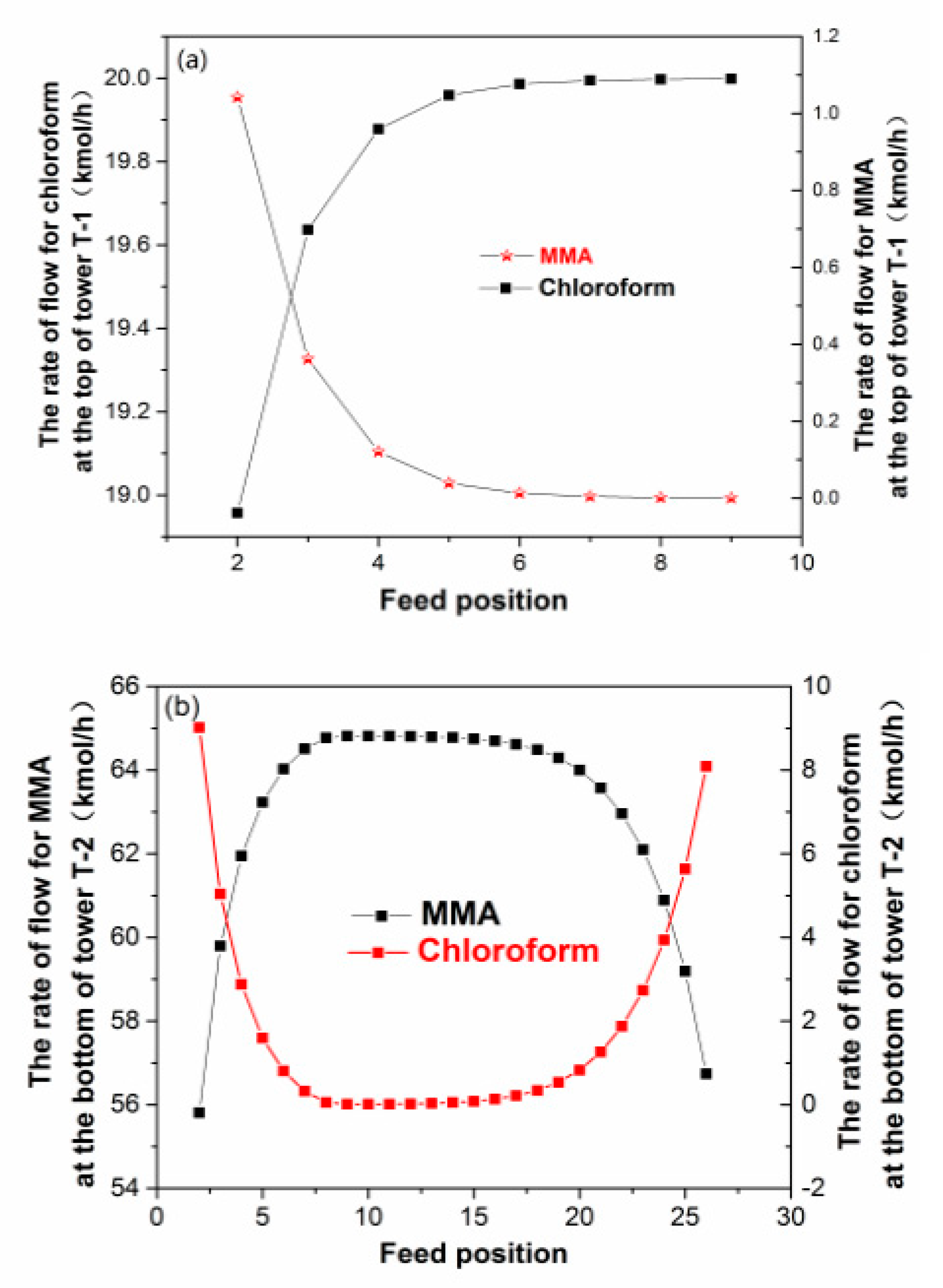
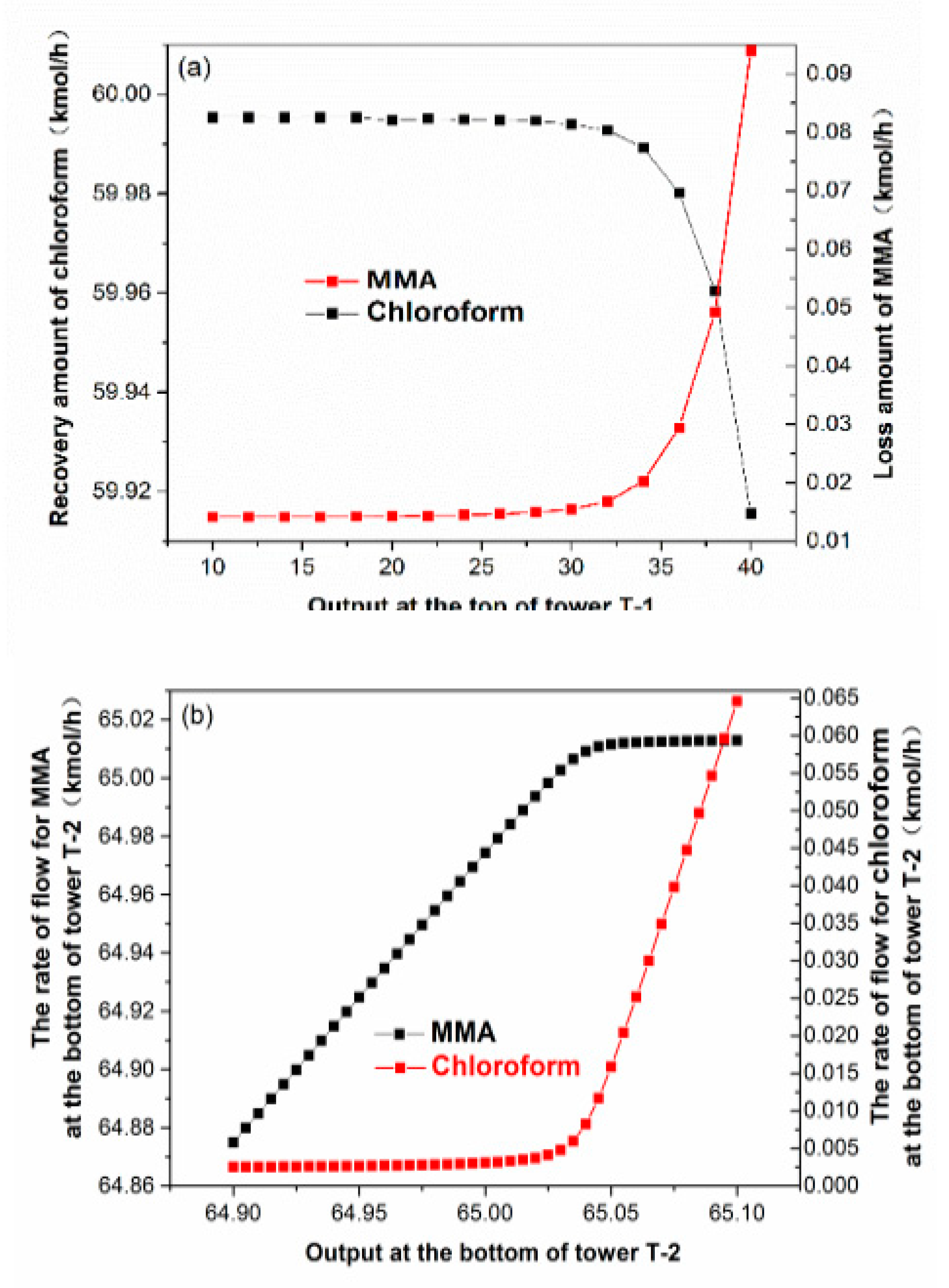
3.3.2. Design of a Promising Chloroform Recovery Process

The proposed chloroform recovery process includes two kinds of chloroform recovery towers with low and high pressure, respectively. The operating pressure in the high-pressure column T-2 is 3 bar, three times larger than that in the low-pressure column T-1 tower. The operating temperature is 60.7 and 98.9 °C for T-1 and T-2, respectively (seen in Figure 6). For the T-1 tower, the condensed-gas phase materials are discharged continuously at the top of tower, and there is no reboiler at the bottom of the tower, while a kettle-type reboiler is used in tower T-2, with no condenser at the top of T-2 for accurate simulation and calculation.
The next analysis focuses on the determination of essential parameters for towers T-1 and T-2, such as the feed position, the number of the plate, and the top output, using the RadFrac model in Aspen Plus.
Figure 7 shows the flow rate for MMA and chloroform as a function of the number of the plate. As for tower T-1 in Figure 7a, the flux of MMA at the top of the tower decreases rapidly, being the exact opposite of that of chloroform, when the number of the plate is relatively low (<10). Both the flux of MMA and chloroform remain approximately stable as the number of plates continues to increase. Similarly, as shown in Figure 7b, the flow rate of MMA at the bottom of the tower T-2 at first increases quickly as the number of plates increases from 2 to 15, and rises more slowly as the number of plates changes from 15 to 27. It is almost unchanged when the number of plates is greater than 27, resulting into optimal numbers of plates of 10 and 27 for towers T-1 and T-2, after the consideration of the maximal flux of chloroform and the minimal flux of MMA, respectively. Moreover, the relationship between the feed position and component is studied in Figure 8. For tower T-1 in Figure 8a, the constituent content of chloroform in the top of the tower increases sharply with the number of plates growing up, and the corresponding transformation law for MMA is the opposite. However, they all reach their stable value at the same time when the number of the plates is ca. 8. Interestingly, the variation tendency of the constituent content of MMA is like a parabolic curve as the number of plates increases (as clearly seen in Figure 8b), and the flux of MMA is the maximum as the number of plates is ca. 9, where the constituent content of chloroform is the minimum simultaneously, which provides theoretical evidence for determining the optimal position of the towers T-1 and T-2.
The influence of output in towers T-1 and T-2 on the separation effect is investigated by sensitivity analysis in Figure 9. The initial value is 20 Kmol/h. For tower T-1 in Figure 9a, there is no significant change in the amount of loss of MMA with the top output smaller than 28 Kmol/h and then increasing at a high rate of speed. The recovery amount of chloroform decreases slowly at the first stage (top output from 10 to 30 Kmol/h), and reduces sharply with a top output greater than 30 Kmol/h. The top output in tower T-1 is controlled at ca. 22 Kmol/h. Clearly, the optimal bottom output in tower T-2 is ca. 65 Kmol/h because of the lower flow of chloroform and the higher flower of MMA (seen in Figure 9b).

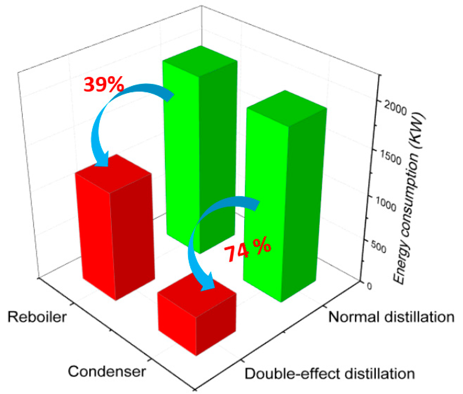
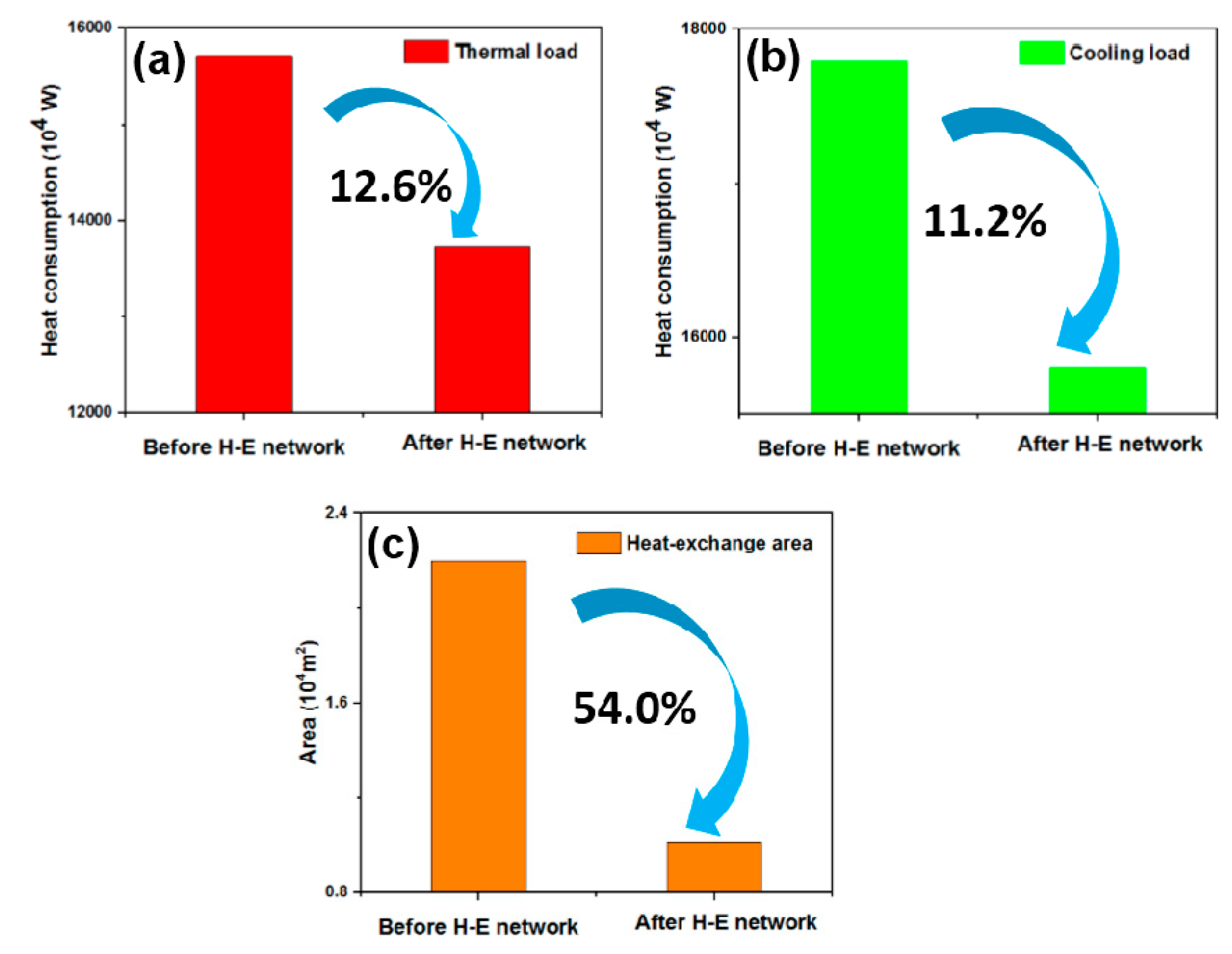
3.4. Energy-Saving Optimization

Energy-saving or cost-saving is essential for material-preparation, process design, etc. in almost all areas [28,29,30,31], an especially in the including industrial production of MMA. The heat exchanger network design is used to reduce energy consumption in this working by using the software-Aspen Energy Analyzer (Version 8.4, Aspen Technology, Inc., MA, USA), based on loop and pinch-point design principles, which includes several conditions of no utility cooler above the pinch-point, no utility heater under the pinch-point, and no heat exchange across the pinch-point, etc. Figure 10 shows the energy consumption change before and after optimizing the heat-exchange network, with the corresponding fitting diagram, displayed in Figure S2 and Table S1 in the Supporting Information. It is worth mentioning that before the heat-exchange (H-E) network, there is no heat exchange between one process hot stream and a process cold stream (i.e., without using utilities). Clearly, through the integrated heat exchange network design, heating steam consumption is reduced by 12.6%, and the cooling utility is reduced by 11.2% that is, the thermal and cooling loads after heat-exchange network design are much lower than before energy-saving optimization, with the heat-exchange area falling by 54 percent, indicating the great advantage of heat-exchange network research.

4. Conclusions

In summary, a novel preparation process of MMA with extensive applications has been successfully designed via an improved green direct methylation method using Aspen Plus simulation software. Methanol is used to efficiently adsorb MAL, and a double-effect distillation design with T-1 and T-2 towers helps to separate MAL from the mixture of MAL and chloroform, which is a critical step for the production of MMA. The purity of the MMA product can reach 99.9% following recycle streams, double-effect distillation process controllability, and heat-exchange network optimization. Thus, this purposed green process for producing MMA exhibits productivity and energy-saving superiority, providing valuable theoretical guidance for the practical production of MMA or its derivatives in many domains.

Supplementary Materials

The following are available online at https://www.mdpi.com/2227-9717/7/6/377/s1. Figure S1. The purification process of MMA using a normal distillation design. Figure S2. The fitting result diagram of processes for MMA before and after optimizing the heat-exchange network. The red and blue lines represent the heat increase and heat decrease of united facilities (such as condenser, reboiler, etc.). Table S1. The cool and hot stream information after the heat-exchange process, based on Figure S2.

Author Contributions

T.L. and X.G. designed the MMA production process, wrote the first draft of the manuscript and conducted the research. Y.W., J.S., X.C., Y.L., X.T. and J.D. completed the optimization of the process using Aspen Plus. A.S.G. and X.W. revised and polished the manuscript. All authors contributed to rechecking the manuscript and approved the final version.

Funding

This research was funded by the National Natural Science Foundation of China (21805014), the scientific and technological research program of the Chongqing Municipal Education Commission (KJQN201801424), the Young Scientist Growth Support Project of Yangtze Normal University (No. 2018QNRC10), the Research Project of Yangzte Normal University (No. 2015XJXM02), and the Guangxi Natural Science Foundation (No. 2016GXNSFBA380216).

Acknowledgments

The authors acknowledge the financial support from the National Natural Science Foundation of China (research core funding No. 21805014), Chongqing Municipal Education Commission (research core funding No. KJQN201801424), Yangtze Normal University (No. 2018QNRC10 and No. 2015XJXM02), and the Guangxi Natural Science Foundation (research core funding No. 2016GXNSFBA380216).

Conflicts of Interest

The authors declare no conflict of interest.

References

  1. Bai, H.; Walsh, F.; Gludovatz, B.; Delettre, B.; Huang, C.L.; Chen, Y.; Tomsic, A.P.; Ritchie, R.O. Bioinspired hydroxyapatite/poly(methyl methacrylate) composite with nacre-mimetic architecture by a bidirectional freezing method. Adv. Mater. 2016, 28, 50–56. [Google Scholar] [CrossRef] [PubMed]
  2. Engelis, N.G.; Anastasaki, A.; Nurumbetov, G.; Truong, N.P.; Nikolaou, V.; Shegiwal, A.; Whittaker, M.R.; Davis, D.P.; Haddleton, D.M. Sequence-controlled methacrylic multiblock copolymers via sulfur-free raft emulsion polymerization. Nat. Chem. 2016, 9, 171–178. [Google Scholar] [CrossRef] [PubMed]
  3. Ogura, Y.; Terashima, T.; Sawamoto, M. Terminal-selective transesterification of chlorine-capped poly(methyl methacrylate)s: A modular approach to telechelic and pinpoint-functionalized polymers. J. Am. Chem. Soc. 2016, 138, 5012–5015. [Google Scholar] [CrossRef] [PubMed]
  4. Bendic, V.; Dobrotă, D.; Dobrescu, T.; Enciu, G.; Pascu, N.E. Rheological issues of phase change materials obtained by the complex coacervation of butyl stearate in poly methyl methacrylate membranes. Energies 2019, 12, 917. [Google Scholar] [CrossRef]
  5. Wang, X.Y.; Sun, X.L.; Wang, F.; Tang, Y. SaBOX/copper catalysts for highly syndio-specific atom transfer radical polymerization of methyl methacrylate. ACS Catal. 2017, 7, 4692–4696. [Google Scholar] [CrossRef]
  6. Singh, M.K.; Shokuhfar, T.; Gracio, J.J.A.; Sousa, A.C.M.; Fereira, J.M.D.F.; Garmestani, H.; Ahzi, S. Hydroxyapatite modified with carbon-nanotube-reinforced poly(methyl methacrylate): A nanocomposite material for biomedical applications. Adv. Funct. Mater. 2008, 18, 694–700. [Google Scholar] [CrossRef]
  7. Kikuchi, Y.; Hirao, M.; Ookubo, T.; Sasaki, A. Design of recycling system for poly (methyl methacrylate) (PMMA). Part 1: Recycling scenario analysis. Int. J. Life Cycle Assess. 2014, 19, 120–129. [Google Scholar] [CrossRef]
  8. Yannicelli, S. Nutrition therapy of organic acidaemias with amino acid-based formulas: Emphasis on methylmalonic and propionic acidaemia. J. Inherit. Met. Dis. 2006, 29, 281–287. [Google Scholar] [CrossRef]
  9. Luda, M.P.; Zanetti, M. Cyclodextrins and cyclodextrin derivatives as green char promoters in flame retardants formulations for polymeric materials. A review. Ploymers 2019, 11, 664. [Google Scholar] [CrossRef]
  10. Patil, R.R.; Turgman-Cohen, S.; Šrogl, J.; Kiserow, D.; Genzer, J. On-demand degrafting and the study of molecular weight and grafting density of poly(methyl methacrylate) brushes on flat silica substrates. Langmuir 2015, 31, 2372–2381. [Google Scholar] [CrossRef]
  11. Spivey, J.J.; Gogate, M.R.; Zoeller, J.R.; Colberg, R.D. Novel catalysts for the environmentally friendly synthesis of methyl methacrylate. Ind. Eng. Chem. Res. 1997, 36, 4600–4608. [Google Scholar] [CrossRef]
  12. Nagai, K. New developments in the production of methyl methacrylate. Appl. Catal. A Gen. 2001, 221, 367–377. [Google Scholar] [CrossRef]
  13. Lei, L.; Tao, R.; Shi, J.; Jing, X.; Ma, H.H. Rapid and continuous synthesis of methacrolein with high selectivity by condensation of propanal with formaldehyde in laboratory. Can. J. Chem. Eng. 2017, 95, 1985–1992. [Google Scholar] [CrossRef]
  14. Yan, R.Y.; Li, Z.X.; Diao, Y.Y.; Fu, C.; Wang, H.; Li, C.S.; Chen, Q.; Zhang, X.P.; Zhang, S.J. Green process for methacrolein separation with ionic liquids in the production of methyl methacrylate. AIChE J. 2011, 9, 2388–2396. [Google Scholar] [CrossRef]
  15. Wu, Y.C.; Hsu, C.S.; Huang, H.P.; Chien, I.L. Design and control of a methyl methacrylate separation process with a middle decanter. Ind. Eng. Chem. Res. 2011, 50, 4595–4607. [Google Scholar] [CrossRef]
  16. Chang, W.L.; Chien, I.L. Energy-saving design and control of a methyl methacrylate separation process. Ind. Eng. Chem. Res. 2016, 55, 3064–3074. [Google Scholar] [CrossRef]
  17. Mizuno, N.; Han, W.; Kudo, T.; Iwamoto, M. Direct oxidation of isobutane into methacrylic acid over Cs, Ni, and v-substituted H3PMo12O40 heteropoly compounds. Stud. Surf. Sci. Catal. 1996, 101, 1001–1010. [Google Scholar]
  18. Yamamatsu, S.; Yamaguchi, T.; Yokota, K.; Nagano, O.; Chono, M.; Aoshima, A. Development of catalyst technology for producing methyl methacrylate (MMA) by direct methyl esterification. Catal. Surv. Asia 2010, 14, 124–131. [Google Scholar] [CrossRef]
  19. Diao, Y.Y.; He, H.Y.; Yang, P.; Wang, L.; Zhang, S.J. Optimizing the structure of supported Pd catalyst for direct oxidative esterification of methacrolein with methanol. Chem. Eng. Sci. 2015, 135, 128–136. [Google Scholar] [CrossRef]
  20. Delikonstantis, E.; Scapinello, M.; Stefanidis, G.D. Process modeling and evaluation of Plasma-assisted ethylene production from methane. Processes 2019, 7, 68. [Google Scholar] [CrossRef]
  21. Yu, N.; Li, L.M.; Chen, M.Q.; Wang, J.X.; Liu, D.; Sun, L.Y. Novel reactive distillation process with two side streams for dimethyl adipate production. Chem. Eng. Process. 2017, 118, 9–18. [Google Scholar] [CrossRef]
  22. Delikonstantis, E.; Scapinello, M.; Stefanidis, G.D. Investigating the plasma-assisted and thermal catalytic dry methane reforming for syngas production: Process design, simulation and evaluation. Energies 2017, 10, 1429. [Google Scholar] [CrossRef]
  23. Vikse, M.; Watson, H.A.J.; Gundersen, T.; Barton, P.I. Simulation of dual mixed refrigerant natural gas liquefaction processes using a nonsmooth framework. Processes 2018, 6, 193. [Google Scholar] [CrossRef]
  24. Zhai, R.R.; Liu, H.T.; Wu, H.; Yu, H.; Yang, Y.P. Analysis of Integration of mea-based CO2 capture and solar energy system for coal-based power plants based on thermo-economic structural theory. Energies 2018, 11, 1284. [Google Scholar] [CrossRef]
  25. Sarda, P.; Hedrick, E.; Reynolds, K.; Bhattacharyya, D.; Zitney, S.E.; Omell, B. Development of a dynamic model and control system for load-following studies of supercritical pulverized coal power plants. Processes 2018, 6, 226. [Google Scholar] [CrossRef]
  26. Tian, W. Study on Catalysts for Selective Oxidation of Isobutylene to Methacrolein; Jiangnan University: Wuxi, China, 2008. [Google Scholar]
  27. Li, G.H.; Zhang, S.J.; Li, Z.X.; Li, M.X.; Zhao, W. Preparation of methyl methacrylate by one-step oxidative esterification of methacrolein. Chin. J. Process Eng. 2004, 4, 508–512. [Google Scholar]
  28. Jin, L.L.; Zhang, C.Y.; Fei, X.J. Realizing energy savings in integrated process planning and scheduling. Processes 2019, 7, 120. [Google Scholar] [CrossRef]
  29. Guo, X.G.; Li, X.M.; Lai, C.; Jiang, X.; Li, X.L.; Shu, Y.J. Facile approach to the green synthesis of novel ternary composites with excellent superhydrophobic and thermal stability property: An expanding horizon. Chem. Eng. J. 2017, 309, 240–248. [Google Scholar] [CrossRef]
  30. Yang, H.C.; Xie, Y.S.; Hou, J.W.; Cheetham, A.K.; Chen, V.; Darling, S.B. Janus membranes: Creating asymmetry for energy efficiency. Adv. Mater. 2018, 30, 1801495–1801506. [Google Scholar] [CrossRef]
  31. Guo, X.G.; Lai, C.; Jiang, X.; Mi, W.H.; Yin, Y.J.; Li, X.M.; Shu, Y.J. Remarkably facile fabrication of extremely superhydrophobic high-energy binary composite with ultralong lifespan. Chem. Eng. J. 2018, 335, 843–854. [Google Scholar] [CrossRef]
Figure 1. Comparison diagram of different production processes of methyl methacrylate (MMA).
Processes 07 00377 g001
Figure 2. The process design sketch of synthetic process of MMA by isobutylene direct methylation method.
Processes 07 00377 g002
Figure 3. Effect of stage number on the flow rate of MAL (fMAL) in the bottom of the absorber column.
Processes 07 00377 g003
Figure 4. The flow rate of MAL (fMAL) in the bottom of the absorber column as a function of absorbent flow rate.
Processes 07 00377 g004
Figure 5. Energy consumption comparison of normal and double-effect distillation.
Processes 07 00377 g005
Figure 6. Chloroform recovery process simulation based on double-effect distillation by the Aspen Plus software.
Processes 07 00377 g006
Figure 7. The flow rate for MMA and chloroform at the top of tower T-1 (a) and at the bottom of tower T-2 (b) as a function of the number of plates in the respective towers.
Processes 07 00377 g007
Figure 8. The relationship between the feed position and the rate of flow for MMA and chloroform at the top of tower T-1 (a) and the rate of flow for MMA and chloroform at the bottom of tower T-2 as a function of feed position (b).
Processes 07 00377 g008
Figure 9. (a) The recovery amount of chloroform and loss amount of MMA as a function of the output at the top of tower T-1, and (b) the rate of flow for MMA and chloroform at the bottom of tower T-1 versus the output at the bottom of tower T-2.
Processes 07 00377 g009
Figure 10. The change in heat consumption for thermal load (a) and cooling load (b), and the heat-exchange area (c) before and after heat-exchange (H-E) network optimal design.
Processes 07 00377 g010

