Article

Analysis of Overlying Strata Movement and Disaster-Causing Effects of Coal Mining Face under the Action of Hard Thick Magmatic Rock

1
Department of Chemistry and Chemical Engineering, Jining University, Qufu 273100, China
2
State Key Laboratory of Mining Disaster Prevention and Control Co-Founded by Shandong Province and the Ministry of Science and Technology, Shandong University of Science and Technology, Qingdao 266590, China
3
Graduate School of Engineering, Nagasaki University, Nagasaki 852-8521, Japan
*
Authors to whom correspondence should be addressed.
These authors contributed equally to this work.
Processes 2018, 6(9), 150; https://doi.org/10.3390/pr6090150
Submission received: 9 August 2018 / Revised: 24 August 2018 / Accepted: 24 August 2018 / Published: 1 September 2018
(This article belongs to the Special Issue Fluid Flow in Fractured Porous Media)

Abstract

:
When the hard and thick key strata are located above the working face, the bed separation structure is easy to be formed after mining because of the high strength and integrity of the hard and thick key strata and the initial breaking step is large. After the hard, thick strata are broken, the overburden will be largely collapsed and unstable in a large area and the dynamic disaster is easily induced. In this study, considering the fundamental deformation and failure effect of coal seam, the development law of the bed separation and the fractures under hard and thick magmatic rocks and the mechanism of breaking induced disaster of hard and thick magmatic rocks are studied by similar simulation tests. The results of the study are as follows: (1) The similar material ratio of coal seam is obtained by low-strength orthogonal ratio test of similar materials of coal seam, that is, cement:sand:water:activated carbon:coal = 6:6:7:1.1:79.9. (2) The magmatic rocks play a role in shielding the development of the bed separation, which makes the bed separation beneath the magmatic rock in an unclosed state for a long time, providing space for the accumulation of gas and water. (3) The distribution pattern of the fracture zone shows different shapes as the advancing of working face and the fracture zone width of the rear of working face coal wall is larger than that of the front of the open-off. (4) The breaking of magmatic rocks will press the gas and water accumulated in the bed separation space below to rush towards the working face along the fracture zone at both ends of the goaf. The above results are verified through the drainage borehole gas jet accident in the Yangliu coal mine. The research results are of great significance for revealing the occurrence process of dynamic disasters and adopting scientific and reasonable preventive measures.

Graphical Abstract

1. Introduction

There are often magmatic rock intrusions in coal measures strata and the variation process and occurrence state have great influence on mining safety [1,2,3]. When the overburden of the working face contains tens of meters or even hundreds of meters of magmatic rock, due to the large thickness, high strength, good integrity and large initial breaking step of the magmatic rock, the hard and thick strata are suspended in the large area after the working face is mined and the lower bed separation space is large, which is easy to cause the stress of the stope to be concentrated and its breaking and movement easily induces strong dynamic phenomena and even leads to dynamic disasters such as mine shock, large surface subsidence, bed separation water, gas outburst, rock burst and so on, which poses a serious threat to mine safety production, causing casualties and economic losses [4,5,6,7]. Magmatic rocks are prevalent in most of Chinese mining areas, such as the Huaibei, Yanzhou and Datong coal fields [8,9,10]. During the mining process, the hard and thick strata break down, resulting in the occurrence of dynamic disasters. For example, in China, Huafeng coal mine is covered with 400–800 m thick magmatic rocks and the abutment pressure during the mining process is abnormal [11]. Since 1992, rockbursts have occurred tens of thousands of times and the maximum magnitude is up to 2.9. The number of damage to the working face is 108 times, forcing the working face to stop production 12 times, resulting in a total of 43 serious injuries and countless number of roadway maintenance, adversely affecting social and economic benefits. During the mining process of Huafeng mine, the surface subsidence has a jump growth after the breaking of the thick magmatic rock. The collapse and cracks on the ground have severely damaged farmland and buildings. On 17 July 2011, a gas jet occurred at the ground #2 drainage borehole from the 10,414 working face of the Yangliu mine in China. During the gas jet period, the water outlet of 87# rack (borehole location) in the working face was abnormal and the water inflow reached heights of up to 46 m3/h. The entire process lasted 33 h, with gas discharge of 166,383 m3 and the water inflow in the working face reached 7845.6 m3. The analysis shows that the dynamic phenomena in the 10,414 working face, such as the gas jet from drainage borehole and the roof water burst, are caused by high igneous rock collapse, which results in the rapid closure of the bottom separation space and induces water-gas outburst. Therefore, it is of great theoretical significance and application value for the control of rock strata and prevention and control of dynamic disasters to study the evolution law of the mining induced bed separation and fracture under the hard and thick magmatic rocks and to reveal the mechanism of the corresponding dynamic disasters.
At present, many scholars have applied numerical simulation, theoretical analysis and on-site observation methods to study the occurrence of dynamic disasters and overburden structures under hard and thick strata for mining [12,13,14,15,16]. Guo studied the mechanism of the rock burst of hard and thick upper strata and proposed the method of overburden bed separation grouting for controlling rock bursts [17]. Taking the No.103up02 working face of Baodian coal mine as an engineering example, according to the field measured microseismic data, Wu studied the law of the overlying hard and thick sandstone breaking caused by the mining face and explained the relationship between the microseismic data and the rock movement [18]. In view of the two layers of hard and thick strata overlying the working face, microseismic monitoring was carried out on the site by Ning et al. and the relationship between the fracture of hard thick rock strata and microseismic data was studied by using the law of microseismic distribution and the prevention measures were proposed [19]. Jiang used numerical simulation method to analyze the stress distribution characteristics, energy evolution law of the working face and surface subsidence under hard and thick strata and found that the vertical stress and energy reaches the maximum before the hard and thick strata break and the vertical stress and energy decrease after the hard and thick strata break but the subsidence of the ground surface increases sharply [11]. Based on the special geological conditions of two layers of hard and thick strata overlying the working face of Yangliu coal mine, Xu used theoretical analysis to derive the analytical formula of the fracture of hard and thick strata and verified the theoretical model by numerical simulation and field data measurement. Based on the key strata theory and numerical simulation method [20]. Wang et al. analyzed the fracture of hard sandstone roof and found that the coal and gas dynamic disaster in the working face is caused by the fracture of hard and thick sandstone [21]. Based on the key strata theoretical analysis of strata movement, He et al. believed that the mine pressure reaches the maximum when the key strata of the overburden fracture, which easily leads to the occurrence of strong mine earthquake and rock burst [22]. Wang et al. analyzed gas disaster characteristics and evolution rules under the igneous sill in the Haizi coal mine, and gas control methods were proposed and tested [23]. Xuan et al. used UDEC numerical simulation to study the mining stress evolution law under magmatic rocks and explained the causes of coal and gas outburst disaster from the perspective of stress [24]. In summary, the existing research uses field measurement, theoretical analysis and numerical simulation to study and analyze the disaster mechanism and breaking law of hard and thick strata in working face mining. Although the field measured data are reliable, they cannot reflect the characteristics of bed separation development and fracture distribution in the whole strata. Theoretical analysis is often based on field measurements and experimental results, it is difficult to systematically analyze the development of the bed separation and the distribution of fractures. Numerical simulation technology is currently the most widely used research technique and some scholars have introduced stochastic modelling of crack propagation, discrete element method, fracture toughness into numerical calculations and achieved good results [25,26,27,28,29]. But it also has some shortcomings. For example, it is difficult to achieve true restoration in the simulation of overlying rock movement process. The physical similar material simulation test can approach the real simulation of the collapse movement, the bed separation development and the fracture formation process of the overburden. However, in the physical similar simulation material test, the existing research rarely considers the influence of the fundamental deformation and damage of the coal seam on the overburden movement.
Therefore, in view of previous studies, the similar simulation test method is adopted in this study. The ratio of similar materials in coal seam is firstly determined by the low-strength orthogonal ratio test of the coal seam similar materials and then the law of the bed separation and fracture development under the hard and thick magmatic rocks during the mining process is studied and analyzed and finally the breaking mechanism of the hard and thick magmatic rocks is proposed, which is of great significance to predict and prevent dynamic disasters of coal mining under the hard and thick strata.

2. Experimental Study on Low-Strength Orthogonal Ratio of Similar Materials in Coal Seam

2.1. Selection of Ratio Test Scheme

After investigating the existing similar material test ratios for simulating coal seams, the aggregates are mainly coal fines or sand and the cement is mostly made of gypsum and cement [30]. Comparing the comprehensive investigation data, in order to choose a more reasonable ratio scheme, coal fines, sand, activated carbon were chosen as aggregate, cement or gypsum as cement. First of all, a preliminary strength test was performed on the cement and the gypsum and after the cement was preferably used, an orthogonal test was performed. The test piece size was φ 50 mm × 100 mm. The test piece making mold and some test pieces are shown in Figure 1. The test was carried out using the Shimadzu electronic universal testing machine.

2.2. Low-Strength Orthogonal Ratio Test and Scheme Optimization

2.2.1. Cement Optimization

The test selected gypsum and cement as cement, respectively. After the test piece was finished, the test piece was tested for strength. The test results are shown in Table 1. According to the similarity theory, similarity ratio and mechanical properties of coal seams in similar simulation tests [31], combined with the test results of Table 1, the low-strength of gypsum and cement can meet the needs of the test. For different proportions of gypsum, uniaxial compressive strength was 85–118 kPa, for different ratios of cement, uniaxial compressive strength was 114–456 kPa, which means that when coal fines are used as the main aggregate, the strength of the test piece is stronger when cement is used as cement. In order to meet the needs of the test coal body strength, this test used cement as a cement for similar simulated test coal.

2.2.2. Orthogonal Ratio Test Scheme

Select the orthogonal test table of 5 factors and 4 levels (factors are cement, sand, water and activated carbon, the fifth factor is empty, the proportion of coal is determined by the total mass ratio of the above four factors) for orthogonal test. The ratio scheme and results are shown in Table 2.

2.2.3. Optimization of Ratio Scheme for Similar Materials in Coal Seam

According to the geological data of the simulated coal seam and the mine, the average density of the coal seam is 1.2 g/cm3 and the uniaxial compressive strength is 16 MPa. According to the low-strength ratio test results and the similarity theory requirements, the uniaxial compressive strength of the coal seam in the similar material simulation test should be 0.07 MPa and the ratio #5, that is, cement:sand:water:activated carbon:coal = 6:6:7:1.1:79.9, was selected as the ratio of the coal seam in the similar material simulation, the density of the coal seam produced was 0.913 g/cm3 and the uniaxial compressive strength was 0.076 MPa.

3. Similar Simulation Material Test Design

3.1. An Overview of Similar Simulation Test

Similar simulation test is a test method of making model in laboratory using similar materials, according to the actual strata data of coal mines, following similar theory and similarity criterion. After the model is completed, the model is mined and analyzed to observe the movement of the overlying strata. The test results and the laws of overburden movement are analyzed. The similar material simulation method is based on the similar simulation conditions and the formation prototype can be simplified appropriately. If there are many rock layers laid, the upper strata can be properly simplified and converted into corresponding loads as compensation to the top of the model.

3.2. Similar Conditions for Similar Simulation Experiments

The similar material simulation test is based on the similarity theory [32,33,34]. The geometrical similarity, time similarity, bulk density similarity, elastic modulus similarity and Poisson’s ratio similarity must be followed between the laying model and the original model.
  • Geometrical similarity. Assuming that the three vertical dimensions of the original model are X P , Y P , Z P and the corresponding dimensions of the similar model are X m , Y m , Z m , then, the geometric similarity ratio is: C l = X m X p = Y m Y p = Z m Z p .
  • Time similarity. The time similarity ratio is: C t = T m T p = C l .
  • Bulk density similarity. Assuming that the bulk density of the i layer of the original model is γ p i and the bulk density of the rock is γ m i in the similar model, then the similarity ratio of the bulk density is: C γ = γ m i γ p i .
  • Strength similarity. Assuming that the uniaxial compressive strength of each rock layer of the original model is σ c p i , σ c m i and the uniaxial compressive strength similarity coefficient of each layer material is C σ c , then the strength similarity ratio is: C σ c = σ c m i σ c p i = C l C γ .
  • Elastic modulus similarity. Assuming that the elastic modulus of each rock layer in the original model is E p i , E m i , the elastic modulus similarity ratio is C E = E m i E p i = C l C r .
  • Poisson’s ratio similarity. Assuming that the Poisson’s ratio of each rock layer in the original model is μ m i , μ p i , then the Poisson’s ratio similarity coefficient is C u = μ m i μ p i .
In this study, the similar simulation experiment was based on the coal seam geological comprehensive histogram and rock mechanics parameters of the 104 mining area of Yangliu coal mine in Huaibei Mining Group. The thickness of the magmatic rock in the model was 60 m, which was 80 m away from the mining coal seam and the designed coal seam was 8 m thick. There was 8# coal overlying the mining coal seam, but it could not stoped. Select model geometric similarity constant Cl = 200, bulk density similarity constant Cγ = 1.5, then, other similar constants can be obtained: time similarity constant C t = C l 14 , elastic modulus similarity constant C E = C l C γ = 300 , strength similarity constant C σ c = C l C γ = 300 . A 500 kg iron block was applied on the model to simulate some unpaved rock formations.

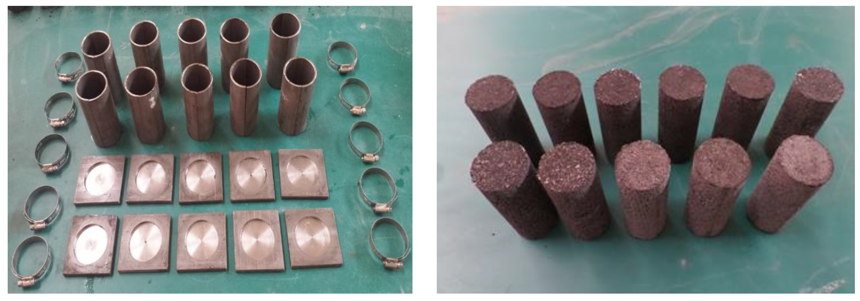
3.3. Test Material Selection and Model Making

In this simulation test, except for the coal seam, other lithology selected fine river sand as aggregate, calcium carbonate and gypsum as cementing materials and mica powder was used as the sandwich material to simulate interlayer joints. The different lithologies of each stratum layer can be achieved through different ratios of materials in the test. According to the determined similarity constant, the ratiometric parameters of the similar material test were determined by the proportioning test, as shown in Table 3.

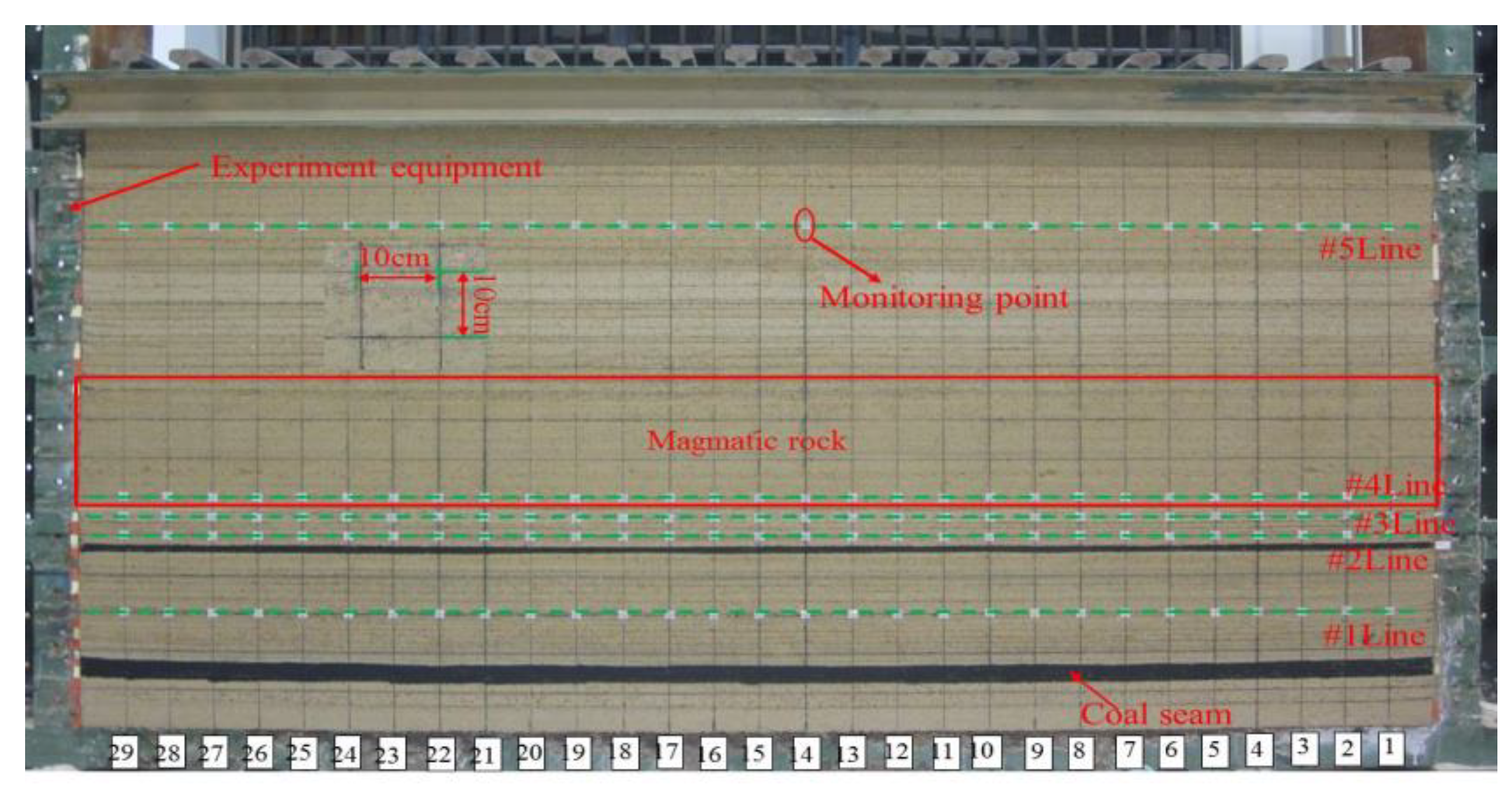
3.4. Test Model Laying

According to the design, the aggregate and cement materials required for each layer were calculated and uniformly mixed together. The stirred materials were evenly laid on the model support, rammed with iron blocks and then a layer of mica powder was evenly spread on the layered surface to simulate interlayer joints. Lay the other strata in turn as described above until the model design height. The weight of overburden which cannot be simulated above the model is implemented by adding weights.

3.5. Monitoring Arrangement and Mining Method

Grids of 100 mm (length) × 100 mm (width) were arranged on the surface of the test model. A total of five monitoring lines were arranged on the model and the distance from the coal seam was 12.5 cm, 32.5 cm, 37.5 cm, 42.5 cm and 112.5 cm, respectively. Each monitoring line was equipped with 29 measuring points, numbering #1 to #29 respectively. The test model was excavated 50 mm each time and the interval between two excavations was generally 1.5 to 2 h. Record the state of the overburden structure with a camera before each excavation and record the test phenomenon in time. The total station was used to record the displacement change state of the monitoring points during the simulation. The model monitoring line and point layout are shown in Figure 2.

4. Evolution Process of Overburden Bed Separation under Hard Thick Magmatic Rock Conditions

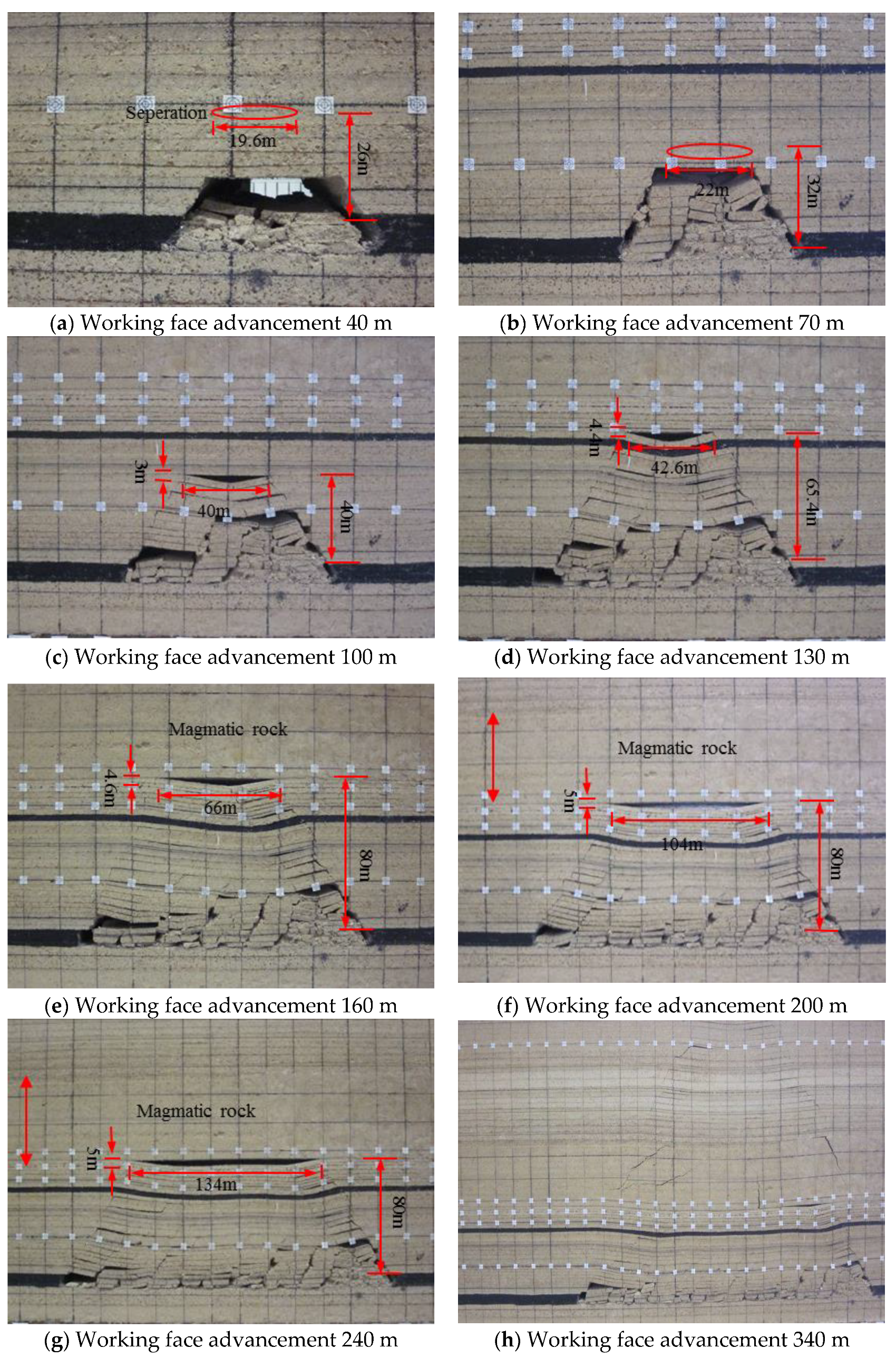
4.1. Overburden Bed Separation Morphology and Developmental Height Evolution

The whole process of the overburden bed separation evolution can be visually displayed by the method of similar simulation test, as shown in Figure 3.
Figure 3a shows that when the working face advances 40 m, the falling immediate roof cannot fully enrich the goaf, causing the lower part of the unfallen roof to lose support and bending and sinking. Due to the difference in lithology, the roof strata are not synchronously bent. The sinking results in the bed separation of the siltstone-mudstone interface at 26 m above the coal seam, with a span of 19.6 m. When the working face advances 70 m, Figure 3b shows that the main roof of the working face is pressed and the bed separation position is moved up to 32 m above the coal seam and the bed separation span is slightly increased but the shape of the bed separation remains the same. As the mining area continues to increase, when the working face advances 100 m, the working face is periodically pressed. Figure 3c shows that the roof of the working face is broken and moved in a large area. The height (the maximum displacement difference of the upper and lower strata at the largest bed separation) and the shape of the bed separation space change rapidly, the height of the bed separation space is instantaneously increased to 3 m, the span reaches 40 m and the bed separation develops to 40 m above the coal seam and the distribution pattern of the bed separation changes. When the working face advances 130 m and 160 m, as shown in Figure 3d,e, the overburden fracture movement is carried out in groups and the shape of the bed separation gradually develops to the higher strata and develops to the bottom of the magmatic rock. The vertical height of the bed separation is 4.6 m and the span reaches 66 m. When the working face advances 200 m and 240 m, the overlying rock falls in a large area and the fallen strata in the middle of the goaf is gradually compacted. As shown in Figure 3f,g, the height of the bed separation space below the magmatic rock increases to 5 m and the span reaches 104 m, 134 m respectively, the development pattern of bed separation increases in both horizontal and vertical directions. When the working face advances 340 m, the magmatic rock breaks and loses stability and the magmatic rock and its upper strata sink and the bed separation under the magmatic rock is closed.
In summary, under the condition that the working face is covered with hard and thick magmatic rocks, the evolution characteristics of the overburden bed separation are mainly characterized by the change of the morphology and developmental height. For the bed separation morphology, as shown in Figure 4, as the working face advances, the falling immediate roof cannot completely fill the goaf and the upper strata of the goaf does not move synchronously, resulting in the bed separation. With the advance of the working face, the goaf falls and the range of the fractures increases continuously in both the height and the length. The middle part of the fractured rock mass is hinged, forming a “triangular” shaped bed separation zone with the upper unbroken strata and compared with the previous bed separation, the volume of the bed separation is significantly increased. As the working face continues to advance, the “triangular” shaped bed separation zone is developed to the bottom of the hard and thick key strata. Under the shielding of the hard and thick key strata, the bed separation does not continue to develop upwards but is developed into a “basin” at the bottom of the hard and thick key strata. The bed separation has experienced the entire process of appearance-expansion-closing at the bottom of the hard and thick key strata.

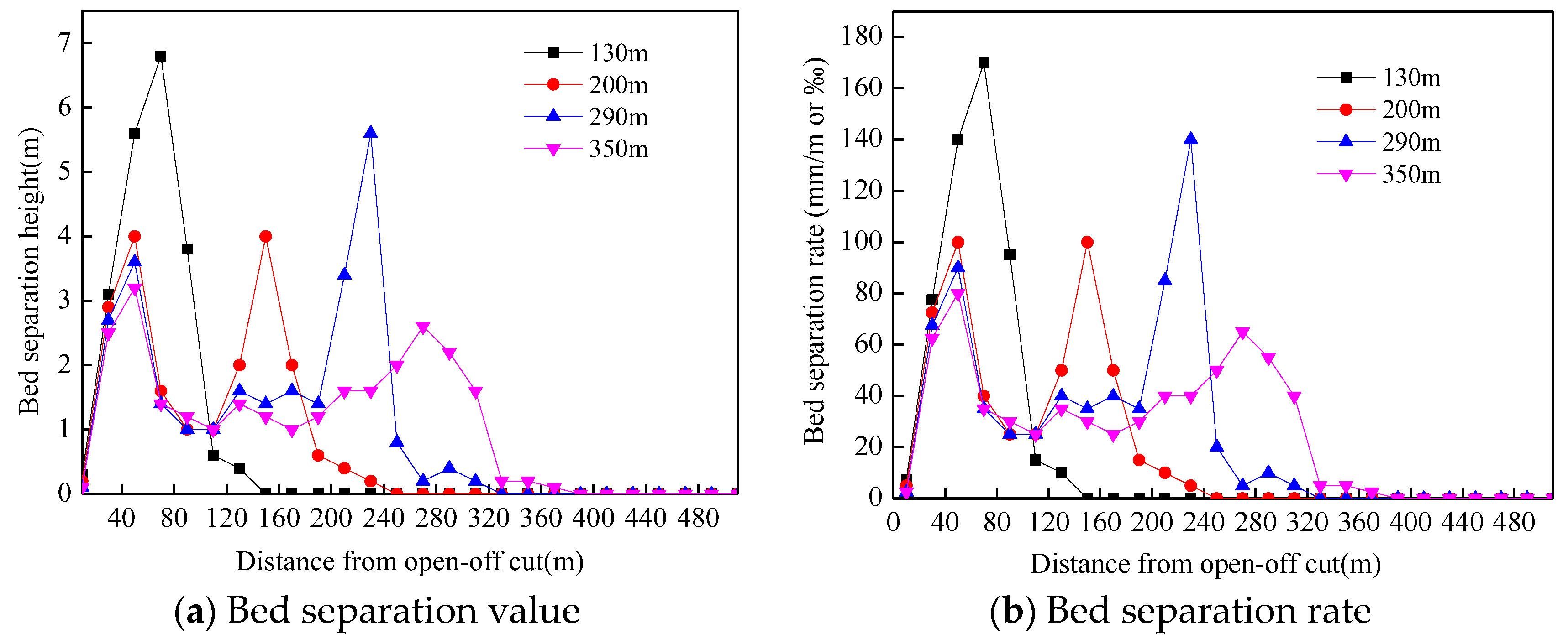
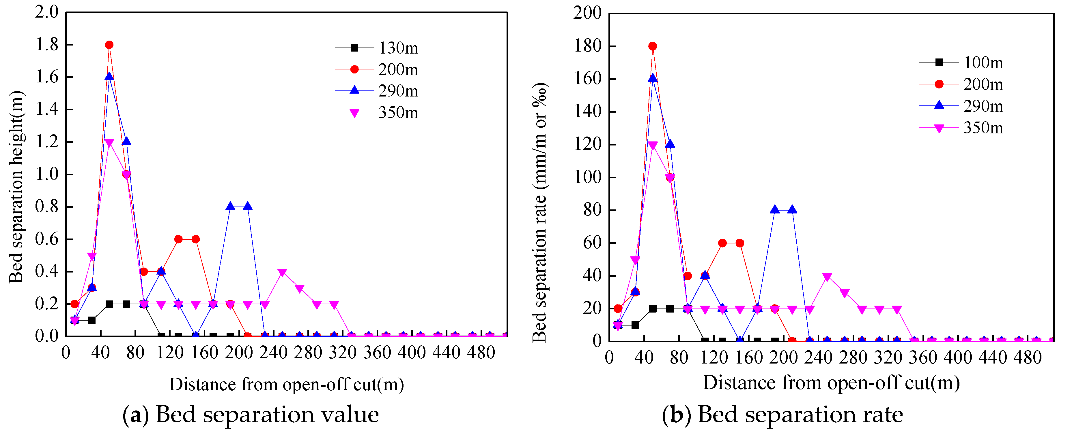
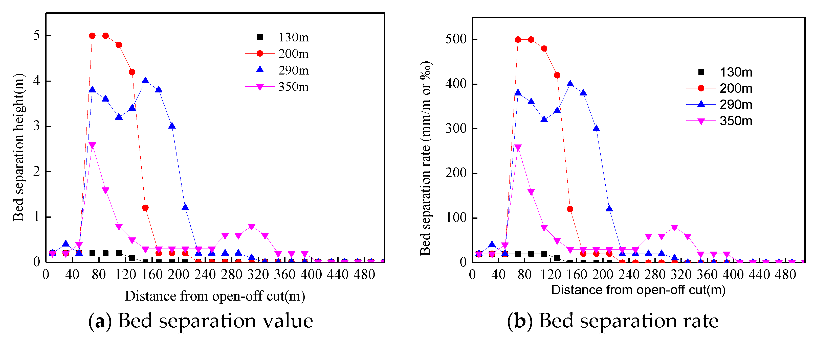
4.2. Dynamic Evolution Law of Mining-Induced Overburden Bed Separation

The bed separation value (bed separation height between adjacent strata, m) and the bed separation rate (bed separation value in unit thickness, mm/m or ‰) can quantitatively describe the dynamic process of overburden bed separation during coal mining. According to the sinking amount of each monitoring point in the mining process, the dynamic change law of the bed separation value and the bed separation rate between the monitoring lines is calculated. Figure 5, Figure 6 and Figure 7 shows the dynamic changes of the bed separation value and the bed separation rate between monitoring lines #1 and #2, #2 and #3, #3 and #4 respectively under different advancing lengths.
As shown in Figure 5, when the working face advances 130 m, the main roof of the working face is periodically collapsed and the falling height of the roof has not touched the strata where the measuring line 2 is located and the maximum bed separation value between the monitoring lines #1 and #2 reaches 6.8 m. The bed separation rate is as high as 170‰ and the maximum bed separation value is located in the middle of the goaf. As the working face continues to advance, the high strata break down and the bed separation value and the bed separation rate between the monitoring lines will decrease. When the working face advances 200 m, the bed separation value and the bed separation rate between the monitoring lines are greatly reduced. The maximum bed separation value is only 4 m, the maximum bed separation rate is 100‰ and the bed separation value and the bed separation rate is reduced by 41%. The fallen strata in the middle of the goaf are gradually compacted and the bed separation between the monitoring lines is closed or reduced, resulting in a significant change in the distribution of the bed separation value and the bed separation rate. The peaks are located at 50 m in front of the open-off cut and behind the coal wall respectively. When the working face advances 290 m and 350 m, the distribution of the bed separation value and the bed separation rate are similar to that of 200 m. The peaks of the bed separation value and the bed separation rate before the open-off cut are slightly reduced compared with 200 m but the peaks position is stable at 50 m in front of the open-off cut and the peaks distribution in front of the open-off cut are approximately equal.
As shown in Figure 6, the variation of the distribution pattern of the bed separation value or the bed separation rate between the monitoring lines #2 and #3 is basically the same as that of the monitoring lines #1 and #2. The #2 line was arranged in the sub-critical strata. The #3 line follows closely the #2 line movement. The bed separation between the monitoring lines is quickly compacted, so that the maximum bed separation value in the “Camel Valley” position is only 4 m before the magmatic rock is broken (working face advance 340 m). When the working face advances 350 m, the magmatic rock has been broken and the bed separation between the monitoring lines is basically compacted, leaving only the 0.2 m remnant bed separation. In addition, when the working face advancement length is greater than 130 m, the peak value of bed separation in front of the open-off cut is gradually decreased. Figure 5 and Figure 6 show that the bed separation value between the #2 and the #3 is much smaller than that of the #1 and the #2 but the distance between the #2 and the #3 is only 10 m, so the bed separation does not change significantly.
The bed separation value and the bed separation rate between the magmatic rock and the lower rock are in a dynamic process, as shown in Figure 7. When the working face advances 130 m, the overburden movement does not affect the strata where the #3 is located. There is almost no bed separation between the #3 and the #4. As the working face continues to advance, the lower strata of the magmatic rock begin to bend, break and sink and the bed separation between the magmatic rock and the lower strata continues to expand. When the working face advances 200 m, the maximum bed separation value between the monitoring lines reaches 5 m and the bed separation rate is as high as 500‰. At this time, the bed separation value between the monitoring lines reaches the maximum. As the working face continues to advance, the bed separation value between the monitoring lines undergoes a stabilization-reduction-closing process. When the working face advances 290 m, the maximum bed separation value between the monitoring lines is reduced to 4 m and the bed separation value in the middle of the goaf is reduced to 3.2 m. The central part of the suspended magmatic rock has been obviously bent and sunk. When the working face advances 350 m, the magmatic rock breaks and loses stability and the bed separation is basically closed except for the rear of the coal wall and the front of the open-off cut. Compared with before breaking, the maximum bed separation rate in front of the open-off cut is reduced by 120‰ and the maximum bed separation rate behind the coal wall is reduced by 320‰.

5. Analysis of Evolution Law of Mining-Induced Overburden Fractures

The similar simulation test results show that the fracture distribution in the overburden has obvious zoning characteristics, as shown in Figure 8. Figure 8 shows that after mining of coal seam, the overburden breaks to produce fractures and as the working face advances, the fracture range expands in height and width. As the mining activity progresses, new fractures continue to occur. Under the action of the overburden, the original part of the fractures is gradually compacted, forming a compacted and fractured areas. The boundary shape of the compaction zone and the fracture zone is approximately trapezoidal. When the fracture development does not reach the magmatic rock, as shown in Figure 8a, the upper boundary of the compaction zone is lower than the upper boundary of the fracture zone. When the fractures develop to the lower surface of the magmatic rock, due to the shielding effect of the magmatic rock on the fracture development, the height of the fracture zone before the magmatic rock breaks no longer develops upward, while the middle part of the goaf is compacted, resulting in the upper boundary of the compaction zone coinciding with the upper boundary of the fracture zone, as shown in Figure 8b,c. After the magmatic rock is broken, the height of the fracture zone changes rapidly and the fracture zone height develops to the top of the model. The distribution of the fracture zone also undergoes singularity change. The boundary morphology of the fracture zone evolves into a double trapezoidal distribution with the lower surface of the magmatic rock as the boundary. As shown in Figure 8d. During the development of the fractures, the weak and small thickness strata can only remain stable in a short period of time, which has little effect on the development speed of the fractures, while the strata with large hardness can maintain stability and integrity for a long time and play a vital role in the formation and development of the fractures. Under the shielding effect of the key strata, the height of the fracture zone changes rapidly, especially in the case of overlying the hard and thick key strata. At the early stage of working face mining, the height of the fracture zone is continuously expanded and stops at the magmatic rock. The boundary area of the fracture zone advances with the advancement of the working face. During the process of fracture zone distribution evolution, the width of the largest fracture zone behind the coal wall is larger than the front of the open-off cut and the width of the fracture zone behind the coal wall is constantly changing. The maximum width is about 40–60 m and the width of the fracture zone in front of the open-off cut is stable at around 30 m.
When the working face is covered with hard thick magmatic rocks, the development of overburden fractures has obvious characteristics in the direction of the working face height and advancement. In the height direction, in the early stage of mining, with the working face advancing, the range of fracture development under the magmatic rock expands continuously but the height of the fractures is only developed to the bottom of the magmatic rock under the shielding of hard and thick magmatic rocks. As the working face continues to advance, the hard thick magmatic rock breaks and loses stability and the development range of the fractures above the goaf changes rapidly and the fractures develop instantly to the top of the model. In the advancing direction, the maximum width of the fracture areas behind the coal wall of the working face is larger than the front of the open-off cut. When the hard and thick magmatic rock is broken, the width distribution of the fracture zone remains the same. Under this influence, the gas in the bed separation space below the hard and thick key strata will flood into the working face through the fracture areas behind the coal wall after the hard and thick key strata is broken, resulting in a safety accident.

6. Mechanism of Breaking Induced Disaster of Hard and Thick Magmatic Rocks

The thermal metamorphism near coal seams under the hard thick magmatic rocks is high and the coal gas content is high, which is the main source of the bed separation gas. Through the law of the bed separation and fracture development of the overburden before and after the breaking of the hard and thick magmatic rock, it is known that before the magmatic rock breaks, there is a huge bed separation space between the magmatic rock and its lower strata and it does not communicate with the fractures and the evolution of the developmental morphology of the bed separation and the height of the bed separation space provides a good space carrier for gas accumulation, which plays a good role in trap accumulation. If the bed separation beneath the magmatic rock communicates with the perforating fractures of the lower strata of the magmatic rock, this will provide a natural passage and accumulation space for the accumulation of gas. Under the combined action of vacuum negative pressure and physical properties, the gas released in the coal seam mining process and the gas remaining in the goaf are collected into the bed separation space of the lower part of the magmatic rock through the surrounding fractures, forming a bed separation gas, as shown in Figure 9. The direction of the arrow is the direction of gas flow.
The results of similar simulation test show that the bed separation space at the bottom of the magmatic rock changes dynamically with the mining of the working face. Therefore, the gas in the bed separation space is also in a dynamic process. Magmatic rocks control the development height of the bed separation and fractures and limit the migration height of the gas. When the hard thick magmatic rock breaks, it exerts a strong dynamic impact on the gas in the bed separation, causing the secondary development of the vertical fractures. The bed separation gas is subjected to the strong dynamic pressure and the accumulated gas is partially poured into the working face along the fractures around the goaf, resulting in the gas outburst accident of the working face and the other part is poured out the ground to form drainage borehole gas jet, as shown in Figure 10.

7. Engineering Case Analysis

The 10,414 working face of Yangliu coal mine is located in Suixi County, Huaibei City, Anhui Province, China. The average coal seam is 3.05 m thick and the buried depth is about 600 m. The 10,414 working face mining area is covered with a layer of magmatic rock with a thickness of 60 m, with an average spacing of 80 m from the coal seam. In order to effectively control the gas content of the working face and ensure safe production, four gas drainage holes of diameter 300 mm, such as 1#, 2#, 3-1#, 3# and so forth, were arranged in the working face range, which were 316 m, 515 m, 654 m and 721 m respectively from the open-off cut. The gas drilling arrangement is shown in Figure 11.
At 14 o’clock on the 16 July 2011, the extraction parameters of the 80-type ground pump began to change. The extraction concentration continued to drop from about 90% under normal conditions to about 20% of the lowest point. The extraction flow had a sharp fluctuation from the normal value of 55 m3/min, while negative pressure and temperature fluctuations were not large. At 17:20 on the 17 July, the extraction concentration rose sharply from 20% to 100% in just 32 min and the negative pressure dropped sharply to 0. At the same time, a gas jet occurred at 2# drainage borehole, as shown in Figure 12. The ejecta was a water-gas mixture and the gas jet lasted 21 h and 30 min, with a total amount of 77,400 m3.
Figure 13 shows the relationship between the gas extraction amount and the mining distance in the gas drainage borehole during the mining of the 10,414 working face. As shown in Figure 13 that when the working face advances 500 m, the amount of extraction of the 2# gas drainage hole begins to increase sharply. When the working face advances 525 m, the extraction volume of the 2# gas drainage hole reaches 0.15 m3/min and the gas jet begin to occur. When the working face advances 543 m, the gas extraction volume in the 2# gas drainage hole reaches a peak value of 45.22 m3/min. When the working face advancing distance is greater than 600 m, the gas extraction volume of the wells in all areas is greatly reduced.
The magmatic rock structure area contains a large amount of gas and water. Because the magmatic rock is dense and hard, the gas is not easily diffused and lost. In addition, No. 10 coal is rich in gas. After the working face is mined, the gas adsorbed in the coal seam is liberated and spreads along the fractures in the goaf to the top of the coal seam. According to the results of similar simulation, it is known that in the process of the working face advancing, a large amount of negative pressure separation space is formed between the magmatic rock and the lower rock strata and a large amount of gas and water are drawn into the space due to the caving and sinking of No. 10 coal overburden are not synchronized with magmatic rocks above.
When the magmatic rock sinks quickly, the gas in the bed separation space is squeezed. Since the ground #2 borehole penetrates the bed separation space through the fractures, causing the gas to flow through the borehole to the ground, resulting in the gas jet. According to the site geological and mine pressure data, the reason for the rapid movement of magmatic rocks is probably the fracture of the magmatic rocks. According to the records of the field engineering technicians, when the working face advances 480 m, the microseismic frequency and the microseismic energy level in front of the working face and above the goaf begin to increase. When the working face advances 500 m, the microseismic frequency and energy level increase rapidly and the large energy microseisms occur in front of the work face. As the working face continues to advance, the vibration energy continues to strengthen and large energy events with energy greater than 50,000 J are concentrated in front of the working face, accompanied by the occurrence of drainage borehole gas jet events. According to the on-site analysis, the gas jet of the #2 borehole is caused by the breaking of the overlying hard and thick magmatic rock. The occurrence of the gas jet event in the 10,414 working face confirmed the law of the bed separation and fracture development under the hard thick magmatic rock in mining.

8. Conclusions

  • Through the low-strength mechanical test, the cement with a wider range of strength is selected as the cementing material to carry out the low strength orthogonal ratio test of the similar simulation material of coal seam and the ratio of coal seam which conforms to the actual field and the similar theory is determined, namely cement:sand:water:activated carbon:coal = 6:6:7:1.1:79.9, the density of the coal seam produced is 0.913 g/cm3 and the uniaxial compressive strength is 0.076 MPa.
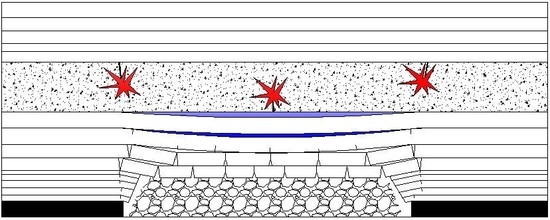
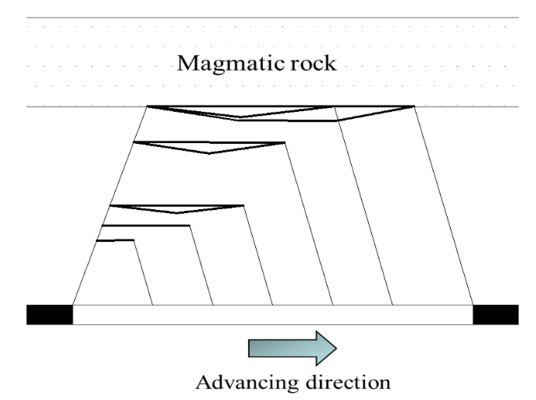
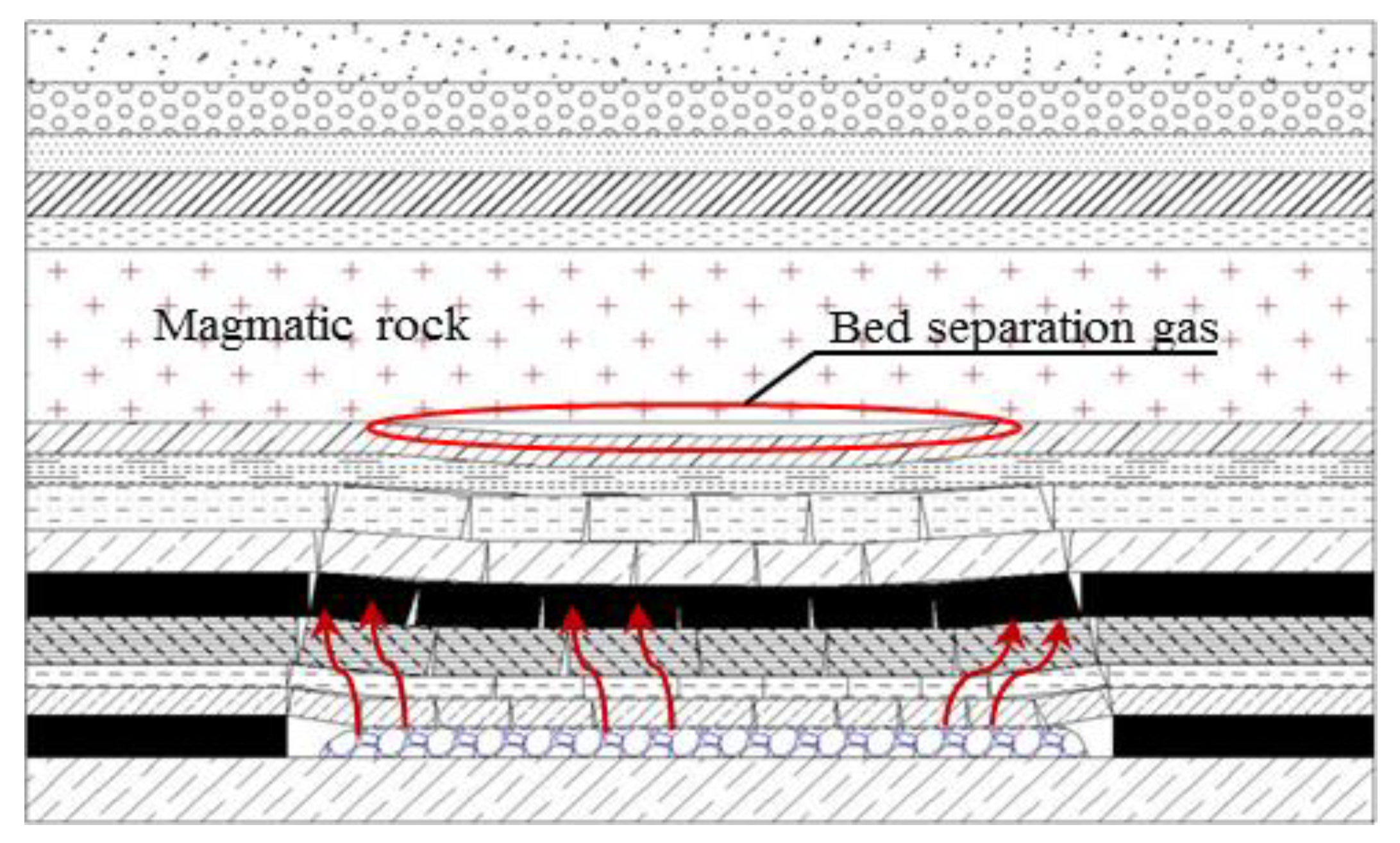
  • Before the hard thick magmatic rock breaks, the developmental height of the overburden bed separation develops upward in a nonlinear way with the advance of the working face. The developmental height of the bed separation is blocked by the hard thick magmatic rock and the height is stopped at the bottom of the magmatic rock and the bed separation is not closed for a long time. As the working face advances, the bed separation changes only in the lateral direction. The bed separation space at the bottom of the hard thick magmatic rock is expanded for a long time, providing a breeding space for the bed separation gas and bed separation water.
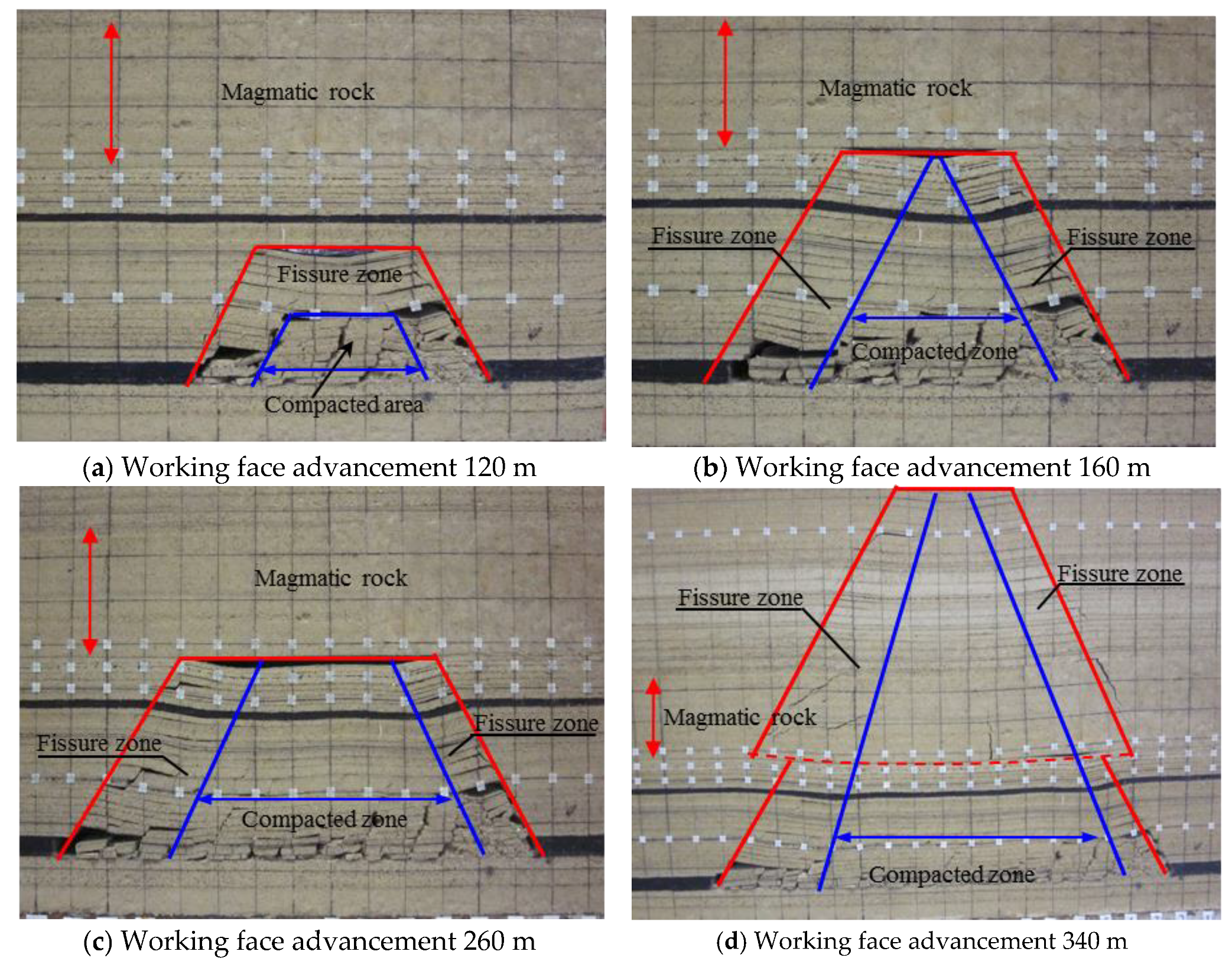
  • When the working face is covered with hard thick magmatic rock, the development of overburden fracture has obvious characteristics in the direction of the working face height and advancement. In the height direction, in the early stage of mining, with the working face advancing, the range of fractures development under the magmatic rock expands continuously but the height of the fractures is only developed to the bottom of the magmatic rock under the shielding of hard and thick magmatic rock. As the working face continues to advance, the hard thick magmatic rock breaks and loses stability and the development range of the fracture above the goaf changes rapidly and the fractures develop instantly to the top of the model. In the advancing direction, the maximum width of the fracture area behind the coal wall of the working face is larger than the front of the open-off cut. When the hard and thick magmatic rock is broken, the width distribution of the fracture zone remains the same.
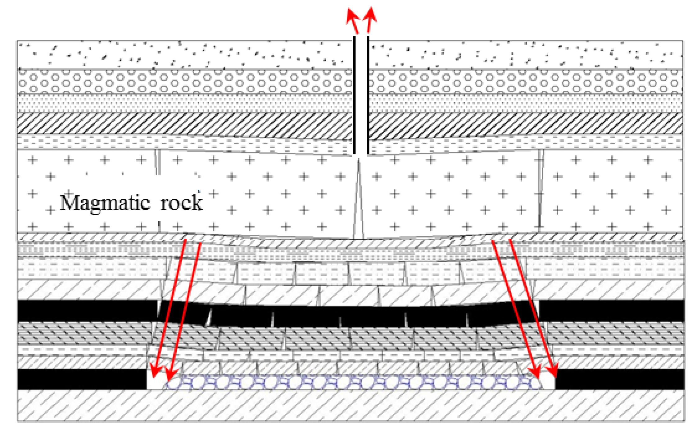
  • Before the magmatic rock breaks, there is a huge bed separation space between the magmatic rock and its lower strata and it does not communicate with the fractures and the evolution of the developmental morphology of the bed separation and the height of the bed separation space provides a good space carrier for gas accumulation, which plays a good role in trap accumulation. If the bed separation beneath the magmatic rock communicates with the perforating fractures of the lower strata of the magmatic rock, this will provide a natural passage and accumulation space for the accumulation of gas. When the hard thick magmatic rock breaks, it exerts a strong dynamic impact on the gas in the bed separation, causing the secondary development of the vertical fractures. The bed separation gas is subjected to the strong dynamic pressure and the accumulated gas is partially poured into the working face along the fractures around the goaf, resulting in the gas outburst of the working face and ground drainage borehole gas jet accidents.

Author Contributions

Conceptualization & Methodology, Q.W. (Quanlin Wu) and Q.W. (Quansen Wu); Writing-Original Draft Preparation, Y.X. and P.K.; Writing-Review & Editing, B.G.

Funding

This research was funded by the Natural Science Foundation of Shandong Province (Grant No. ZR2018PEE007).

Conflicts of Interest

The authors declare that there is no conflict of interests regarding the publication of this paper.

References

  1. Cao, A.; Zhu, L.; Li, F. Characteristics of T-type overburden structure and tremor activity in isolated face mining under thick-hard strata. J. China Coal Sci. 2014, 39, 328–335. [Google Scholar]
  2. Lu, C.P.; Liu, Y.; Wang, H. Microseismic signals of double-layer hard and thick igneous strata separation and fracturing. Int. J. Coal Geol. 2016, 160–161, 28–41. [Google Scholar] [CrossRef]
  3. Jiang, J.; Zhang, P.; Nie, L. Fracturing and dynamic response of high and thick stratas of hard rocks. Chin. J. Rock Mech. Eng. 2014, 33, 1366–1374. [Google Scholar]
  4. Jiang, J.; Xu, B. Study on the development laws of bed-separation under the hard-thick magmatic rock and its fracture disaster-causing mechanism. Geotech. Geol. Eng. 2018, 36, 1525–1543. [Google Scholar] [CrossRef]
  5. Wu, L.; Qian, M.; Wang, J. The influence of a thick hard rock stratum on underground mining subsidence. Int. J. Rock Mech. Min. Sci. 1997, 34, 341–344. [Google Scholar] [CrossRef]
  6. Xu, C.; Cheng, Y.; Ren, T. Gas ejection accident analysis in bed splitting under igneous sills and the associated control technologies: A case study in the Yangliu Mine, Huaibei Coalfield, China. Nat. Hazards 2014, 71, 109–134. [Google Scholar] [CrossRef]
  7. Song, D.; Wang, E.; Liu, Z.; Liu, X. Numerical simulation of rock-burst relief and prevention by water-jet cutting. Int. J. Rock. Mech. Min. Sci. 2014, 70, 318–331. [Google Scholar] [CrossRef]
  8. Wang, W.; Cheng, Y.; Wang, H. Coupled disaster-causing mechanisms of strata pressure behavior and abnormal gas emissions in underground coal extraction. Environ. Earth Sci. 2015, 74, 6717–6735. [Google Scholar] [CrossRef]
  9. Wang, L.; Cheng, Y.; Xu, C.; An, F.; Jin, K.; Zhang, X. Thecontrolling effect of thick-hard igneous rock on pressure relief gas drainage and dynamic disasters in outburst coal seams. Nat. Hazards 2013, 66, 1221–1241. [Google Scholar] [CrossRef]
  10. Wang, J.; Jiang, F.; Meng, X.; Wang, X.; Zhu, S.; Feng, Y. Mechanism of rock burst occurrence in specially thick coal seam with rock parting. Rock Mech. Rock Eng. 2016, 49, 1953–1965. [Google Scholar] [CrossRef]
  11. Jiang, J.; Wu, Q.; Wu, Q.; Wang, P.; Zhang, C.; Gong, B. Study on distribution characteristics of mining stress and elastic energy under hard and thick igneous rocks. Geotech. Geol. Eng. 2018, 1–16. [Google Scholar] [CrossRef]
  12. Jiang, L.; Sainoki, A.; Mitri, H. Influence of fracture-induced weakening on coal mine gateroad stability. Int. J. Rock Mech. Min. Sci. 2016, 88, 307–317. [Google Scholar] [CrossRef]
  13. Jiang, H.; Cao, S.; Zhang, Y. Analytical solutions of hard roof’s bending moment, deflection and energy under the front abutment pressure before periodic weighting. Int. J. Min. Sci. Technol. 2016, 26, 175–181. [Google Scholar] [CrossRef]
  14. Wang, P.; Jiang, J.; Zhang, P. Breaking process and mining stress evolution characteristics of a high-position hard and thick stratum. Int. J. Min. Sci. Technol. 2016, 26, 563–569. [Google Scholar] [CrossRef]
  15. Qian, M.; Miao, X.; Xu, J. Theoretical study of key stratum in ground control. J. China Coal Soc. 1996, 21, 225–230. [Google Scholar]
  16. Dou, L.; Hu, H. Study of OX-F-T spatial structure evolution of overlying strata in coal mines. Chin. J. Rock Mech. Eng. 2012, 31, 453–460. [Google Scholar]
  17. Guo, W.; Li., Y.; Yin, D. Mechanisms of rock burst in hard and thick upper strata and rock-burst controlling technology. Arab. J. Geosci. 2016, 9, 561. [Google Scholar] [CrossRef]
  18. Wu, Q.; Jiang, J.; Wu, Q. Study on the fracture of hard and thick sandstone and the distribution characteristics of microseismic activity. Geotech. Geol. Eng. 2018, 2, 1–17. [Google Scholar] [CrossRef]
  19. Ning, J.; Wang, J.; Jiang, L. Fracture analysis of double-layer hard and thick roof and the controlling effect on strata behavior: A case study. Eng. Fail. Anal. 2017, 81, 117–134. [Google Scholar] [CrossRef]
  20. Xu, C.; Yuan, L.; Cheng, Y.; Wang, K.; Zhou, A.; Shu, L. Square-form structure failure model of mining-affected hard rock strata: Theoretical derivation, application and verification. Environ. Earth Sci. 2016, 75, 1180. [Google Scholar] [CrossRef]
  21. Wang, W.; Cheng, Y.; Wang, H. Fracture failure analysis of hard–thick sandstone roof and its controlling effect on gas emission in underground ultra-thick coal extraction. Eng. Fail. Anal. 2015, 54, 150–162. [Google Scholar] [CrossRef]
  22. He, H.; Dou, L.; Gong, S.; Zhou, P.; Xue, Z. Rock burst rules induced by cracking of overlying key stratum. Chin. J. Geotech. Eng. 2010, 32, 1260–1265. [Google Scholar]
  23. Wang, L.; Cheng, L.; Cheng, Y. Characteristics and evolutions of gas dynamic disaster under igneous intrusions and its control technologies. J. Nat. Gas Sci. Eng. 2014, 18, 164–174. [Google Scholar] [CrossRef]
  24. Mousavi Nezhad, M.; Gironacci, E.; Rezania, M.; Khalili, N. Stochastic modelling of crack propagation in materials with random properties using isometric mapping for dimensionality reduction of nonlinear data sets. Int. J. Numer. Methods Eng. 2018, 113, 656–680. [Google Scholar] [CrossRef]
  25. Mousavi Nezhad, M.; Fisher, Q.J.; Gironacci, E.; Rezania, M. Experimental study and numerical modeling of fracture propagation in shale rocks during brazilian disk test. Rock Mech. Rock Eng. 2018, 51, 1755–1775. [Google Scholar] [CrossRef]
  26. Guo, L.; Latham, J.; Xiang, J. A numerical study of fracture spacing and through-going fracture formation in layered rocks. Structures 2017, 110–111, 44–57. [Google Scholar] [CrossRef]
  27. Park, B.; Min, K. Bonded-particle discrete element modeling of mechanical behavior of transversely isotropic rock. Int. J. Rock Mech. Min. Sci. 2015, 76, 243–255. [Google Scholar] [CrossRef]
  28. Chong, K.P.; Kuruppu, M.D. Fracture toughness determination of layered materials. Eng. Fract. Mech. 1987, 28, 43–54. [Google Scholar] [CrossRef]
  29. Xuan, D.; Xu, J.; Feng, J.; Zhu, J.; Zhu, W. Disaster and evolvement law of mining-induced stress under extremely thick igneous rock. J. China Coal Soc. 2011, 36, 1252–1256. [Google Scholar]
  30. Chen, S.; Wang, H.; Zhang, J.; Xing, H.; Wang, H. Experimental study on low-strength similar-material proportioning and properties for coal mining. Adv. Mater. Sci. Eng. 2015, 3, 1–6. [Google Scholar] [CrossRef]
  31. Dai, H.; Lian, X.; Liu, J. Model study of deformation induced by fully mechanized caving below a thick loess layer. Int. J. Rock Mech. Min. Sci. 2010, 47, 1027–1033. [Google Scholar]
  32. Xiao, T. Study on Surrounding Rock Stability and Control of Deep Roadway in Thick Coal Seam under the Action of Tectonic Stress. Ph.D. Thesis, China University of Mining and Technology, Beijing, China, 2011. [Google Scholar]
  33. Lin, Y. Experimental Rock Mechanics-Simulation; China Coal Industry Publishing House: Beijing, China, 1984. (In Chinese) [Google Scholar]
  34. Kai, W.; Gong, P.; Zhang, X.; Lian, Q.; Li, J.; Duan, D. Characteristics and control of roof fracture in caving zone for residual coal mining face. Chin. J. Rock Mech. Eng. 2016, 35, 2080–2088. [Google Scholar]
Figure 1. Test piece making mold and some test pieces.
Processes 06 00150 g001
Figure 2. Similar simulation test model and monitoring line and point layout.
Processes 06 00150 g002
Figure 3. Evolution law of overburden bed separation.
Processes 06 00150 g003
Figure 4. Evolution process of the bed separation under the hard and thick key strata.
Processes 06 00150 g004
Figure 5. Dynamic evolution of the bed separation between the monitoring lines #1 and #2.
Processes 06 00150 g005
Figure 6. Dynamic evolution of the bed separation between the monitoring lines #2 and #3.
Processes 06 00150 g006
Figure 7. Dynamic evolution of the bed separation between the monitoring lines #3 and #4.
Processes 06 00150 g007
Figure 8. The distribution characteristics of fractures in overburden.
Processes 06 00150 g008
Figure 9. Schematic diagram of the formation of bed separation gas.
Processes 06 00150 g009
Figure 10. Schematic diagram of bed separation gas inrushing.
Processes 06 00150 g010
Figure 11. Schematic diagram of the gas drainage drilling arrangement of the 10,414 working face.
Processes 06 00150 g011
Figure 12. Gas jet at the ground 2# drainage borehole.
Processes 06 00150 g012
Figure 13. Relationship between the gas extraction amount and the mining distance in the gas drainage borehole.
Processes 06 00150 g013
Table 1. Optimum test results of cement.
Test NumberCement (%)Sand (%)Water (%)Activated Carbon (%)Coal (%)Sand to Rubber Ratio (%)Density (g·cm−3)Uniaxial Compressive Strength (kPa)
Gypsum #187110.973.110.130.97285
Gypsum #2126110.570.56.420.96197
Gypsum #3156110.567.54.930.885118
Gypsum #18470.580.510.630.866114
Gypsum #2104111.173.97.90.935228
Gypsum #3127131.166.96.251.089456
Table 2. Low-strength orthogonal ratio test scheme for coal seam similar materials.
Factor NumberCement (%)Sand (%)Water (%)Activated Carbon (%)Coal (%)Density (g·cm−3)Uniaxial Compressive Strength (kPa)Sand to Rubber Ratio
165110.777.30.9179613.83
210770.775.30.9861218.30
387110.973.10.95820410.13
412570.975.10.9581876.75
56671.179.90.9137614.50
6104111.173.90.9352287.90
78470.580.50.86611410.63
8126110.570.50.9493196.42
964130.976.10.95321013.50
1010690.974.11.0121568.10
1186130.772.31.0461479.88
1212490.774.31.0132646.58
136790.577.51.00814614.17
14105130.571.51.0111607.70
158591.176.50.95916710.38
16127131.166.91.0894566.25
Table 3. Ratio of materials and materials for different strata in similar simulation tests.
Rock NumberRock NameThickness (cm)Cumulative Thickness (cm)Proportioning NumberBulk Density (g/cm3)
R-29Siltstone6162.77551.6
R-28Mudstone6156.78641.5
R-27Fine sandstone6150.77821.6
R-26Siltstone5.2144.77551.6
R-25Mudstone5.2139.58641.5
R-24Siltstone5134.37551.6
R-23Mudstone12129.38641.5
R-22Fine sandstone7117.37821.6
R-21Sandy mudstone4.4110.38641.5
R-20Fine sandstone4.8105.97821.6
R-19Mudstone4.6101.18641.5
R-18Siltstone5.496.57551.6
R-17Mudstone3.691.18641.5
R-16Magmatic rock3087.57371.5
R-15Mudstone1.557.58641.5
R-14Fine sandstone2.8567821.6
R-13Sandy mudstone353.28641.5
R-12Siltstone3.250.27551.6
R-118# coal1.6478641.5
R-10Siltstone1.545.47551.5
R-9Mudstone3.243.98641.5
R-8Siltstone3.240.77551.6
R-7Sandy mudstone437.58641.5
R-6Siltstone333.57551.6
R-5Mudstone2.830.58641.5
R-4Siltstone327.77551.6
R-3Piebald mudstone324.78641.5
R-2Siltstone321.77551.6
R-1Fine sandstone1.218.77821.6
CoalCoal417.5
F-1Coarse sandstone13.513.57731.6

