1. Introduction
One of the main challenges for modern science and technology is the search for innovative technologies and the expansion of the use of alternative organic natural resources in the context of a rapid decline in petroleum product reserves. Peat is considered to be one of these valuable natural materials. It is a spongy material, a product of the partial decomposition of organic matter, mostly plants from different wetlands such as swamps, fens, moors, etc. [
1]. This type of solid fuel is currently attracting increasing research interest, as it has high prospects for widespread industrial use due to its availability, simple extraction technology and economic benefits. The global reserves of peat is about 5 × 10
11 tons [
2]. Among caustobioliths, peat stands out both in terms of its physical (high moisture content, loose structure, low density, high porosity) and chemical properties (acidity, humidity, different group composition depending on the deposit and depth). The complexity and diversity of its composition, namely, the presence of a wide class of organic water-soluble and easily hydrolyzed compounds, humic acids, sugars, bitumen, hemicelluloses and cellulose, creates the possibility of using peat in the energy sector, construction, chemical industry, metallurgy and medicine [
3].
Increasing the efficiency of the use of peat resources requires the development of physical and chemical methods for its processing. Nowadays, thermal conversion without oxygen participation (pyrolysis) is the most widely used process, with the mechanism influenced by a wide range of different factors [
4]. The influence of parameters on the pyrolysis process and the yield of products should be noted. A thermogravimetric analysis of pyrolysis showed that during low-rate pyrolysis, a solid residue is formed. It is explained by the fact that at a lower process temperature and a longer processing time, more carbonation products are produced, and at a high heating rate, liquid products predominate [
4]. Also, the yield of the products varies depending on the particle size of the feedstock. If the particle size is large, the heat supplied to the outer surface of the sample will not be able to pass quickly, and it will take longer for the raw material to reach a high pyrolysis temperature. It leads to a slowdown in the heating rate. At the same time, with a smaller particle size, the heat exchange occurs much faster, which ensures a high heating rate. It is worth noting that the low heat transfer rate in larger particles allows them to become more charred compared to the small-sized raw materials. Therefore, an important role is played not only by external exposure conditions, i.e., temperature, pressure, heating rate, but also by the properties of the material itself, i.e., chemical composition, humidity, particle size, content mineral part [
4,
5,
6,
7], during sequential and parallel reactions in the pyrolysis, namely, cross-linking, depolymerization and fragmentation.
Thermal pyrolysis of solid materials, which is based on “conventional” heat sources, is characterized by relatively low thermal conductivity and, accordingly, a low heating rate. In reactors of this type, heat from the source is transferred to the surface of the material and then penetrates inside due to thermal conductivity and/or convection depending on the structure of the material, its properties and phase state. In this case, a large temperature gradient inevitably arises, which complicates the volumetric heating of the processed material. Thereafter, it leads to different conditions for the pyrolysis reaction in the reactor volume and, as a result, to uneven processing of the object.
Microwave methods are currently widely used in various scientific and engineering applications [
8,
9,
10,
11,
12]. The use of microwave radiation for the destruction of organic materials is undoubtedly promising [
13,
14,
15,
16,
17,
18]. Microwave exposure makes it possible to solve the above-described problems inherent in conventional thermal pyrolysis. In contrast, microwave pyrolysis is characterized by volumetric heating, which is less dependent on the thermal conductivity of the material, but it is determined by its absorption capacity and dielectric constant. As a result, microwave radiation provides “instant” heating of processed materials. The relatively high absorption coefficient of electromagnetic energy by organic materials allows a high efficiency of heat transfer to be achieved. Optimization of the microwave reactor design facilitates a uniform distribution of the microwave field in a large volume. Consequently, it helps to achieve a homogeneous temperature distribution, even heating and identical processing conditions for a large volume of material.
It is important to emphasize that high demands are currently placed on increasing environmental friendliness and accident-free technological processes. In this aspect, microwave pyrolysis reactors are advantageous for automating this process, which has less thermal “inertia”. They also have a higher environmental friendliness compared to pyrolysis reactors with burners due to their high emissions of flammable gases.
The research presented in this paper is aimed at improving the method of fragmentation and processing of organic raw materials using microwave radiation. For the first time, a direct comparison was made for processing peat during pyrolysis under “conventional” thermal and microwave exposure. Based on the conducted three-dimensional (3D) modeling, reactor designs were developed to provide identical conditions for the reactions. This made it possible to correctly compare different processing methods, determine their specific features and demonstrate the advantages of microwave pyrolysis.
2. Modeling the Dynamics of Heat Propagation in Different Types of Pyrolysis Reactors
Simulations of the processes of conventional thermal and microwave pyrolysis were carried out using a commercial 3D code, CST Studio Suite, which is suited for multiphysics calculations. The simulation parameters corresponded to the experimental conditions described below in
Section 3. The theoretical analysis was aimed at developing a reactor design that facilitates the correct comparison of these processes and methods for conducting experiments in the same conditions. Thus, an identical geometry of the reaction vessel (a glass Wurtz flask) was adopted.
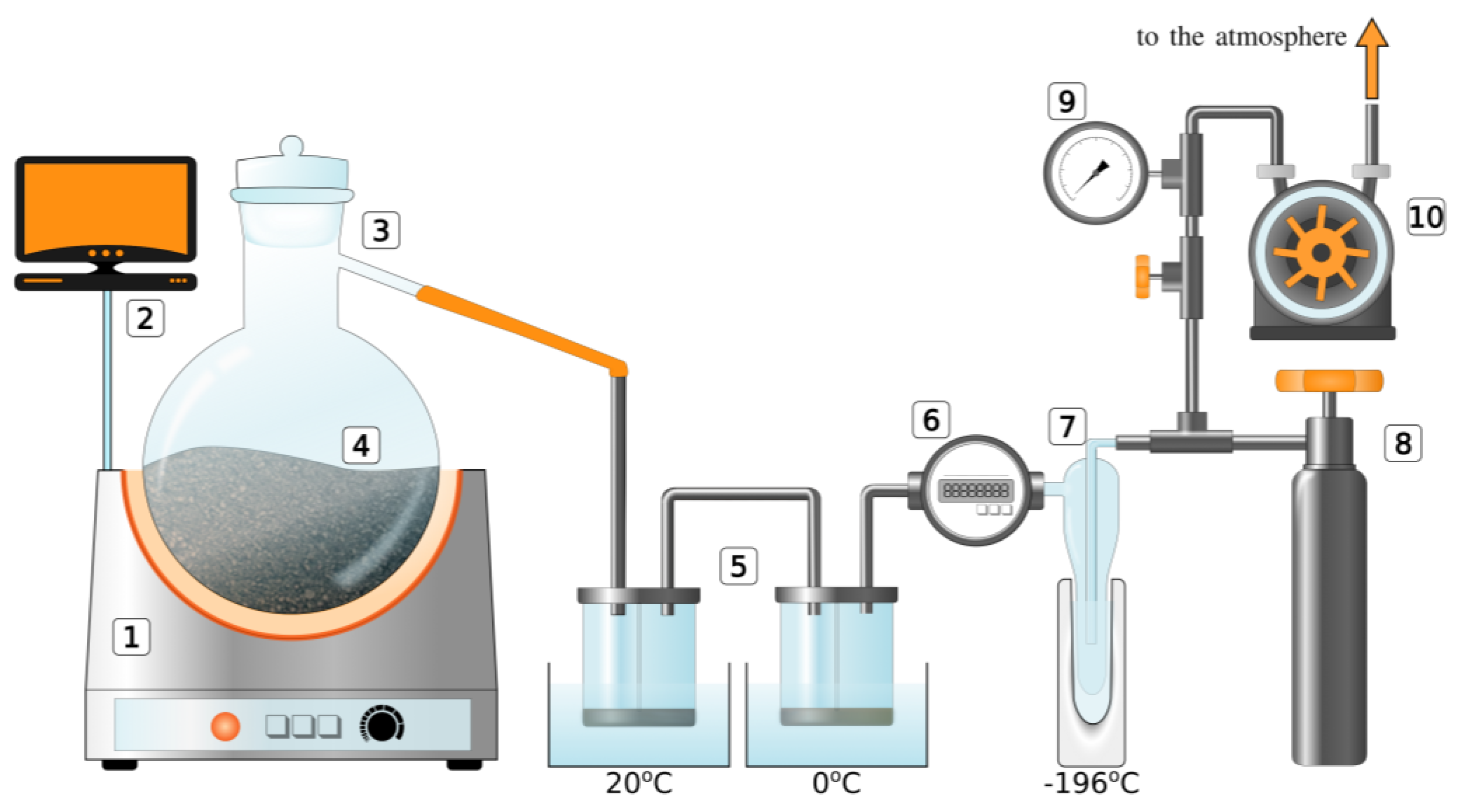
The 3D models of the reactors considered in the simulations are presented in
Figure 1. In the case of conventional thermal pyrolysis (see
Figure 1a), a continuous heat source was located on the outer boundary of the bottom wall of the flask. Under a heat source, there was thermal insulation; thus, all the heat transferred to the flask. Calculation volume boundaries were set to constant room temperature as the flask was placed in open air. Microwave pyrolysis modeling was conducted in two steps: the calculation of microwave distribution and then thermal distribution based on microwave absorption as the source of the heat.
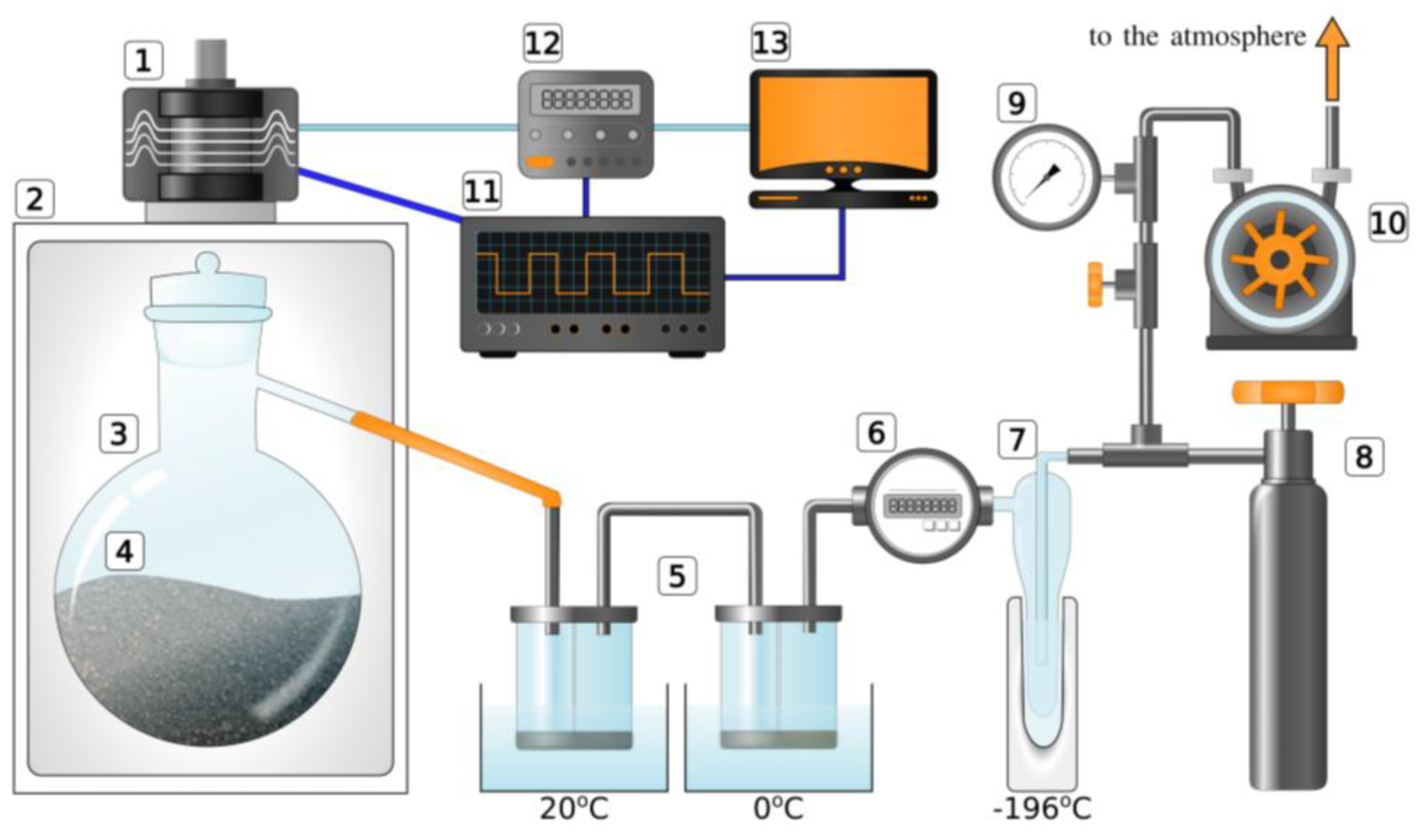
During the simulations of microwave pyrolysis (see
Figure 1b), the flask was placed inside a metal box, providing reflection of the radiation. On top of the box, there was an input single-mode waveguide, which was connected to a microwave source (magnetron). The incident RF wave was fed through this waveguide, irradiating the reaction vessel. The boundaries of the calculated volume, which were considered on the outer surface of the metal walls, were set to a constant room temperature as the box was placed in open air (but without taking into account air flows). The heating power in both cases (for the thermal source and for the microwave source) was taken to be about 500 W. The volume of peat in the simulations was set at the half level of the reaction vessel, which was 200 g, considering the density of the peat. The physical properties of the medium (heat capacity, thermal conductivity, dielectric constant, dielectric loss tangent, etc.) corresponded to the reference values confirmed during the preliminary tests described below (see
Section 3). The temperature gradient distributions were studied in different time periods.
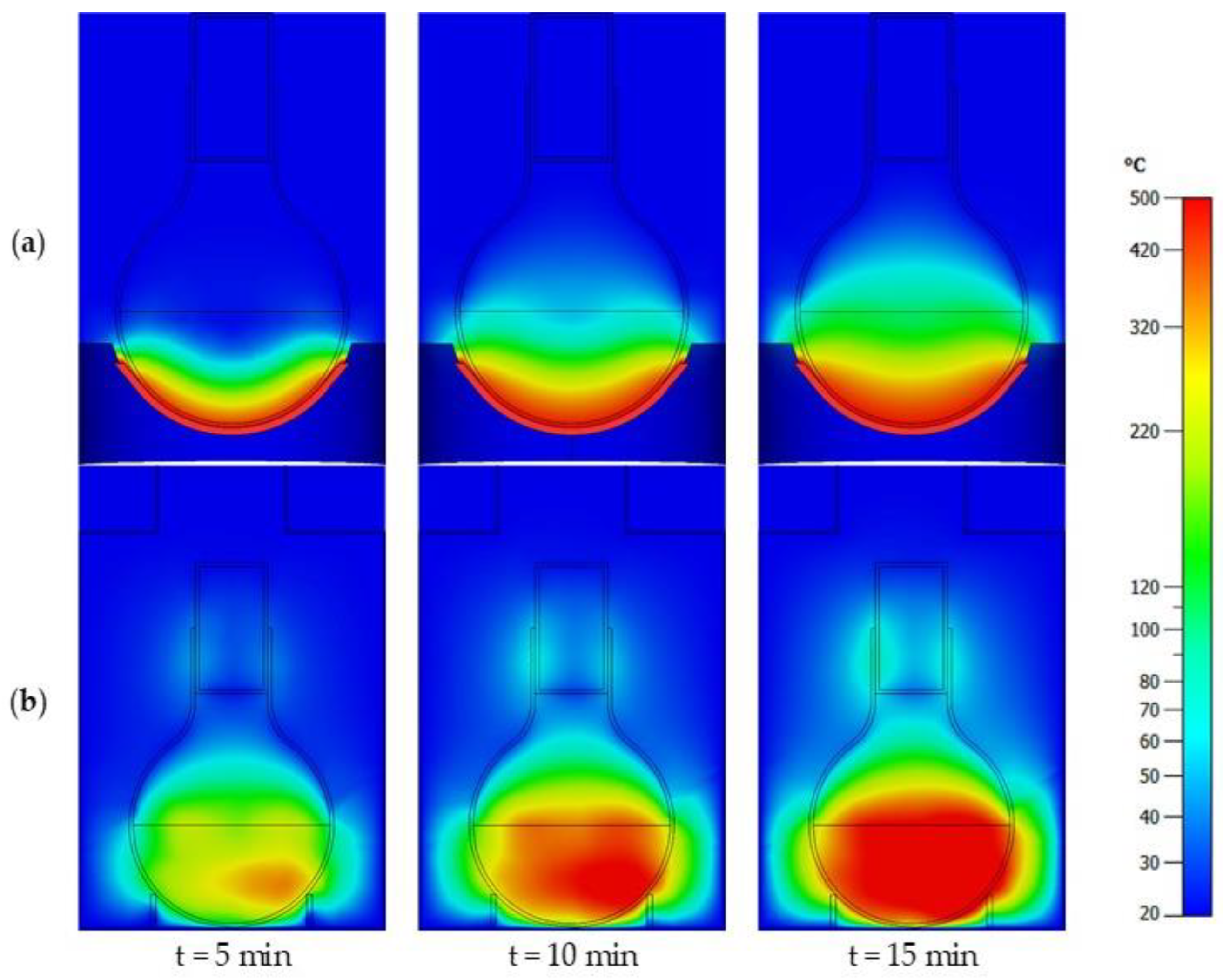
The simulation results presented in
Figure 1 demonstrate instantaneous temperature distributions in the reactor volume at the time moments t = 5 min, 10 min and 15 min. These “snapshots” illustrate the dynamics of heat propagation throughout the volume of processed material. The carried-out modeling confirms the conclusions of the qualitative analysis. Indeed, in the case of thermal heating, the main mechanism of heat transfer is thermal conductivity, with heat gradually spreading from the source deep into the material. As the simulations shows, this process is characterized by a highly heterogeneous temperature distribution across the reactor, overheating in the source area and almost a complete absence of heating in the upper part of the reactor. This leads to a significant difference in the conditions for the pyrolysis reaction in the reactor zones located at different distances from the heat source.
Microwave heating of the material illustrates the fundamentally different dynamics. The “volumetric” nature of microwave absorption causes almost uniform heating, which is actually observed from the very beginning of irradiation. In this case, over time, the uniformity of the spatial distribution of temperature is not violated. As a result, the temperature increases throughout the entire volume of the reactor, and the pyrolysis reaction proceeds identically.
3. Preliminary Experiments on Measuring Thermal and Electrodynamic Characteristics of Peat
In order to correctly compare the calculations and experimental results, a series of preliminary experiments were carried out to determine the physical properties of the peat samples under study. The bulk density was measured at different temperatures and at the corresponding humidity, respectively. This technique (see, for instance, [
19]) is based on measuring the mass of peat after a free fall into a container of a set volume. According to this method, the bulk density of peat samples was 273 kg/m
3 before irradiation at room temperature and humidity.
The heat capacity of peat was measured using the calorimetric method by cooling the sample using the next algorithm. At the beginning, a calibration measurement was carried out to determine the calorimeter constant. To achieve this, a system was assembled from a calorimetric vessel filled with distilled water, i.e., an agitator and a K-type electronic thermocouple. The described system was kept at rest for 5 min so that all parts of the calorimeter assumed the same temperature, and then, every 30 s during this time period, the measurement was performed to make sure that the temperature did not change. Then, a little piece of ice of a certain mass was added to the system, the temperature change was measured every 30 min, and the end of a significant temperature change (0.02 K) was recorded. Further, a similar experiment was conducted with a heated peat sample. After the measurements, calculations were carried out according to the following equations:
where
K is the calorimeter constant,
mi is the mass of the ice,
ci is the heat capacity of ice,
mw is the mass of water,
cw is the heat capacity of water, ∆
T is the temperature difference,
cs is the heat capacity of the sample,
t is the final temperature,
t1 is the initial calorimeter temperature, and
t2 is the initial sample temperature,
m2 is the sample mass. As a result of the experiments, the average heat capacity of peat was measured as 1550 J/kg·K.
To measure the dielectric constant and the absorption coefficient (dielectric loss tangent), a specialized stand based on a network analyzer was used. The dielectric constant value measured for peat using this method was 1.6, and the dielectric loss tangent was 3.3 × 10
−2, respectively. This is in good agreement with the results of measurements of these peat parameters carried out earlier using the so-called resonator methods [
20]. However, it should be noted that during the pyrolysis process, the amount of carbon in the product increases, carbonation occurs, and absorption becomes close to the values of a good absorber (~10
−1–10
−2). This allows sufficiently effective radiation absorption.
5. Materials and Methods
5.1. Peat
The main subject of the research is high-moor sphagnum peat with a low degree of decomposition from the Greko-Ushakovskoe deposit (moisture less than 65%, pH = 2.5).
5.2. Procedure for Conducting Experiments
Before conducting experimental studies, preparation of peat samples was carried out according to technological methods described in [
19,
21]. As a result of this sample preparation, when outgassing with a backing vacuum pump, surface and capillary moisture was removed from the pores of the sample; thus, only sorbed and hydrated samples remained [
22].
Experiments on thermal heating of peat were performed according to the following procedure. A sample of peat weighing 200 g was placed in a reaction vessel, closed with a glass stopper on ground sections lubricated with vacuum grease and immersed in the bowl of an electric heating element. The so-called “soft” pyrolysis of peat was carried out at a temperature of about 250–270 °C. In the series of experiments, the sample was heated to the specified level for 10 min, and then, this temperature was maintained for 80 min by periodically turning off/on the heating source. Pyrolysis products were pumped through a fractionation system, including a liquid settling tank and a Richter absorber with a vacuum pump.
Experiments on microwave pyrolysis were organized according to a similar methodology. The mass of the irradiated sample was also 200 g. The industrial magnetron used had a controlled high-voltage power supply for power control and additional water cooling for long-term operation. The parameters of the magnetron and its output signal were monitored using an oscilloscope; the temperature on the wall of the reaction vessel was monitored using a thermal imager after completion of the microwave exposure. In this series of experiments, the process of pyrolytic decomposition of peat was also observed in the temperature range specified above. The process duration was 60 min. Fractionation was performed according to the scheme identical to that used in thermal pyrolysis experiments (see
Figure 3).
5.3. Analytical Methods
In the experiments conducted, the analysis of the solid residue using the CHNS method was carried out using Vario EL Cube. This procedure was performed as follows: The mass of the sample was determined using Toledo XS205DU. The oxidation test tube was filled with WO3 (device standard). Oxygen was supplied to the oxidation tube. After that, according to the combustion products (CO2, H2O, SO2, NO2) detected using thermal conductivity measurement and infrared, the device program automatically calculated the amount of C, H, N and S.
The composition of gaseous and liquid products of peat pyrolysis initiated by microwave radiation was studied using gas chromatography mass spectrometry (GCMS QP2010 Ultra, Shimadzu, Columbia, MD, USA). The sample was mixed with a carrier gas stream (high purity 6.0 helium) at an evaporator temperature of 300 °C. Further, the sample components were separated on an Ultra ALLOY-5 capillary chromatographic column. A temperature programming was applied under the following conditions: 40 °C was maintained in the column for 2 min, and then, the temperature was increased at a rate of 10 °C/min to 250 °C, and this temperature was maintained. The classification of products was achieved using database NIST 11.
6. Results of the Conducted Experiments
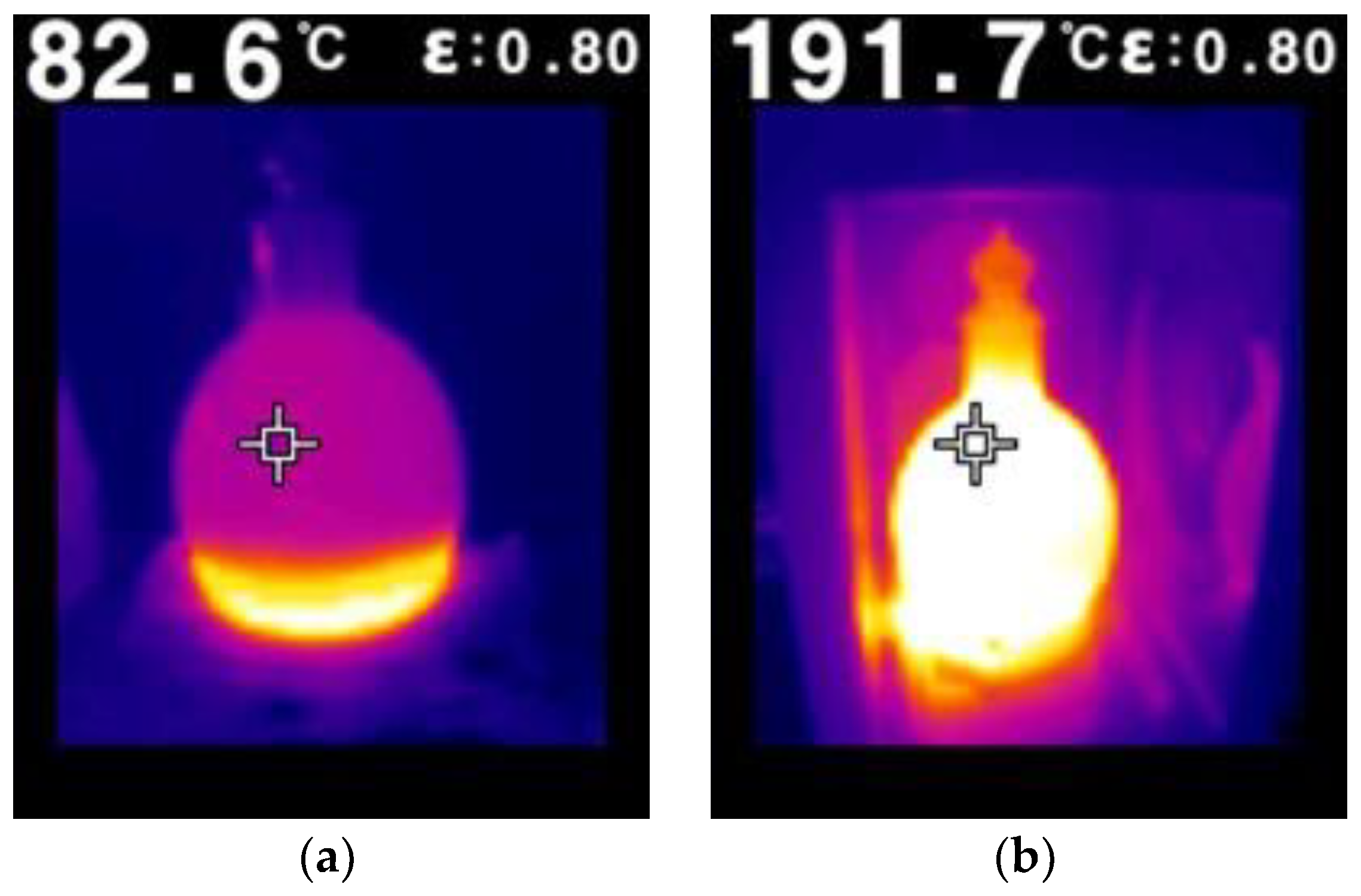
The difference in heating mechanisms in the various types of reactors demonstrated within the framework of the 3D simulation was proved during experiments by measurements using a thermal imaging camera (cf.
Figure 4 and
Figure 1). According to the results of the experiments, thermal heating by TEH (as well as by fire sources) is characterized by a large heterogeneity of the temperature distribution in the reactor, the pronounced maximum of which is concentrated near the wall of contact with the heat source (
Figure 4a). As discussed previously, uneven heating of the sample leads to different rates of reaction in different parts of the reactor. This is confirmed by the analysis of reaction products carried out during the experiments that contain areas of high-temperature fuel burnout near the wall, while the part of the fuel remote from the heat source remains practically unaffected by heat and is not processed. In contrast, the volumetric nature of heating, which appears in the case of microwave exposure, leads to an almost uniform temperature distribution inside the fuel (
Figure 4b), which ensures identical conditions for the pyrolysis reaction throughout the entire volume of the reactor. As a result, the experiments conducted on microwave pyrolysis demonstrate a deeper and more uniform processing (fragmentation) of peat.
As a part of the experiments, the energy efficiency of the pyrolysis process was evaluated when various heating sources were exploited. The technological parameters of both complexes are summarized in
Table 1. The conducted studies show a significant reduction in the processing time under microwave exposure, which is associated with the more efficient, volumetric nature of such heating. Moreover, the electrical energy consumed per unit mass of pyrolysis products initiated by microwave irradiation is noticeably less than during a similar thermal process. Thus, in the case of microwave pyrolysis, we obtained ~20% energy savings, even when considering its consumption from the outlet. Increasing the efficiency of the microwave source (using more efficient sources) would lead to a further enhancement in the energy effectiveness of this process. This demonstrates the undoubted advantages of the proposed approach.
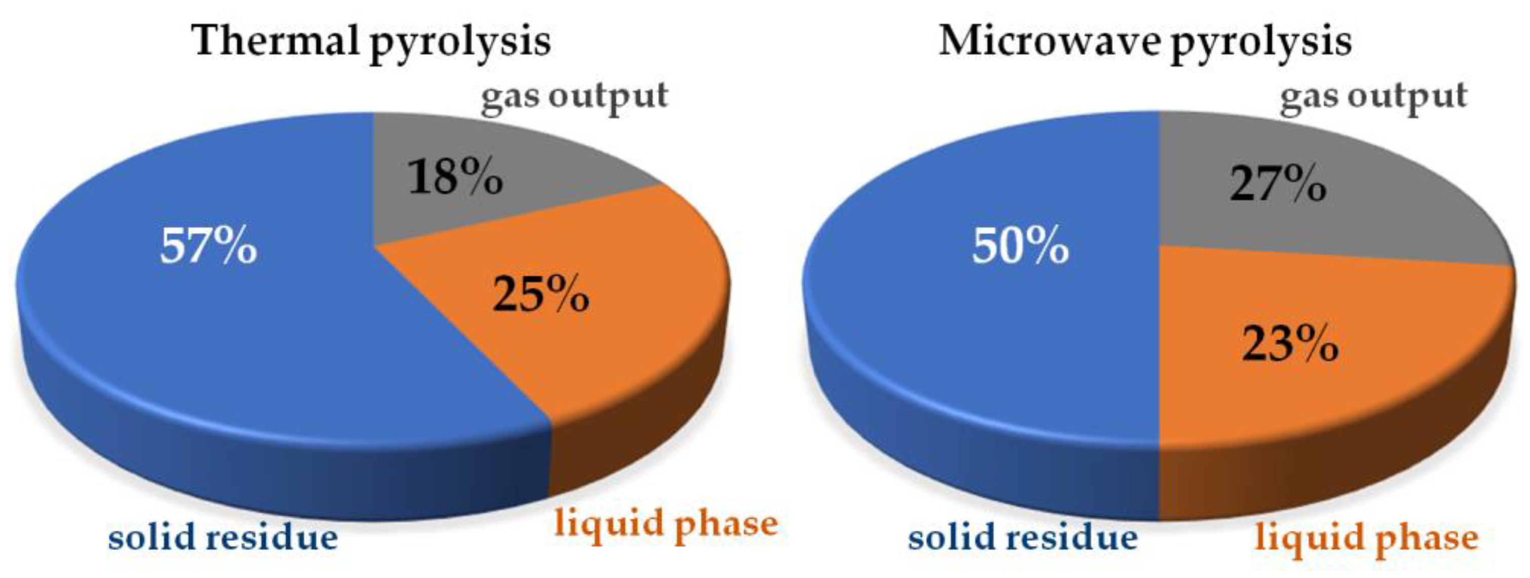
It is also important to note that the process of microwave pyrolysis of peat is accompanied by a higher yield of gas fractions (see
Figure 5). This allows for a further increase in the efficiency of this processing method when burning these gases [
23].
Under the conditions of our experiments, the processing time during pyrolysis was determined by low-thermal conductivity during thermal heating and a relatively large amount of peat used. (A comparable time of thermal processing was observed, for example, in [
4], for even smaller amounts of peat.) Obviously, taking into account the relatively good absorption of peat (see
Section 3), the processing time during microwave pyrolysis can be significantly reduced with an increase in the irradiation intensity (which allowed our experimental complex). However, the aim of our study was to correctly compare the pyrolysis process with different heating in the most similar conditions. As a result, the same heating power (500 W) and a close processing times were applied.
Peat is a multicomponent system consisting of three parts: organic, mineral and water. The organic part of the peat includes chemical elements such as carbon, oxygen, sulfur and nitrogen (especially carbon, oxygen and hydrogen). The ratio of carbon and hydrogen in peat determines its thermal characteristics; namely, the proportion of these components is used to predict its calorific value. Nitrogen and sulfur are contained in peat in small quantities. The presence of nitrogen and sulfur in the elemental composition of the initial organic raw materials is not favorable for peat pyrolysis. The feedstock during processing emits a mixture of several types of SOx and NOx gases, which are toxic in nature and cannot be considered environmentally safe. The content of sulfur and nitrogen in peat is extremely low, which ensures that pyrolysis does not lead to the release of harmful gases.
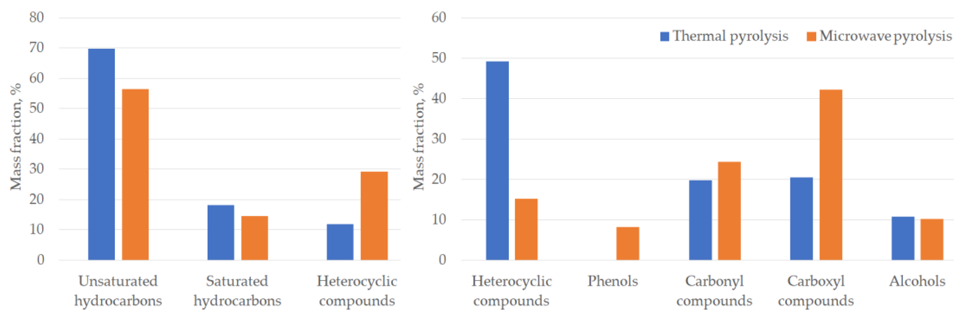
The results of the analysis of pyrolysis products are presented in
Figure 6. The main classes of organic compounds and their percentage content in the reaction products are shown. According to the GCMS measurements, gaseous products consist of unsaturated and saturated hydrocarbons and heterocyclic compounds (
Figure 6, left). The liquid products during the microwave processing of peat mainly include heterocyclic, carbonyl, carboxyl compounds, alcohols and phenols (
Figure 6, right). The main aliphatic gases may be formed as a result of the pyrolysis of hemicellulose and cellulose. Aromatic hydrocarbons might be obtained as a result of the pyrolysis of lignin [
5,
6].
The mass content of carbon, hydrogen and nitrogen in the solid product obtained as a result of the elemental analysis of the solid product after microwave pyrolysis is given in
Table 2. The elemental analysis carried out shows an increase in the percentage of carbon from 49.4% to 64% and 78% in the case of peat and samples obtained during thermal and microwave pyrolysis, respectively. Note, also, that a lower value of the H/C ratio of the carbonaceous residue after microwave exposure indicates, firstly, high yields of gaseous compounds and deep destruction and, secondly, the production of a solid product with a more porous structure obtained due to a high reaction rate and active gas release. This demonstrates the advantages of microwave pyrolysis both for the production of gaseous products and for the production of oil-absorbing sorbents.
It is shown that deeper decomposition of the feedstock (peat) is achieved under conditions of microwave pyrolysis. The atomic ratios H/C and C/N were also calculated for all samples. In the case of microwave-induced pyrolysis, the H/C ratio is 2.8 times lower compared to the original peat, while the same indicator for the carbonaceous residue after thermal pyrolysis differs by approximately 1.6 times. This may indicate that after microwave treatment, the carbonaceous residue has a higher content of aromatic and unsaturated hydrocarbons relative to the original peat and the sample after heat treatment. It is considerably worth noting the nitrogen content analysis; the C/N ratio almost does not change for the sample after microwave treatment in comparison with the initial one. However, for the thermal pyrolysis residue, the C/N ratio is slightly higher (57 compared to 48). Meanwhile, for the sample after microwave treatment, the mass content of nitrogen is slightly higher than in the original peat—1.8% and 1.2%, respectively. The increase in the N content in the carbonaceous residue after microwave radiation treatment compared to the initial peat sample can be explained by the stability of N-containing compounds, such as heterocyclic aromatic compounds, during thermal conversion [
24].
The products obtained as a result of pyrolysis can be used in various fields. Hydrogen in the composition of the gas fraction is a highly profitable product that can be used as fuel and a raw material for hydrogenation and reduction processes. The carbonaceous residue can become a raw material to obtain effective environmentally friendly sorbents of organic toxicants. After the mineral component removal, the residue is a good basis for the manufacture of sorbents. As discussed above, the conducted experiments have shown that during microwave exposure, gas is released more actively from the volume of the peat sample compared to thermal exposure. This leads to a more porous structure and an extended surface of the carbonaceous residue, which increases its overall sorption capacity. The distinctive features of organic sorbent of natural origin based on peat are significant oil capacity (6–10 g of oil/g of sorbent), hydrophobicity and buoyancy. This group of sorbents is applied manually or with the help of knapsack sprayers. They are biodegradable and can be used on any solid and water surfaces and in a wide temperature range.
7. Conclusions and Discussions
In summary, laboratory reactors were elaborated based on the conducted 3D modeling, which allowed implementation of a series of comparative experiments to study the characteristics of the reaction of the “soft” pyrolysis (thermolysis) of peat using thermal energy sources of a different nature. These experiments demonstrated that one of the main drawbacks of conventional thermal reactors based on electric heating elements or fire sources is a high-temperature gradient due to the low thermal conductivity of organic materials. This complicates their processing, in particular, requiring the use of stirring systems. In contrast, the volumetric and “instantaneous” (on the scale of thermal processes) nature of heating under microwave irradiation allows uniform temperature distribution and identical proceeding of pyrolysis reaction to be practically ensured in a large volume of the microwave reactor; as a result, more uniform and deeper fragmentation of the organic materials is achieved. Microwave reactors allow the reliable control of the parameters and safety of the process of the high-temperature destruction of fuel, as well as high environmental cleanliness. According to the results of the conducted research, the high efficiency of thermal heating during microwave processing of organic raw materials provides a high potential for increasing the reaction rate and reducing the processing time, as well as for enhancing the energy efficiency of the developing experimental complexes.
It is important to note that in previous laboratory work on thermal and microwave pyrolysis, small amounts of peat (~10–50 g) were studied. In our work, for the first time, a direct comparison of thermal and microwave pyrolysis was carried out when applying significantly larger volumes of the product than in previous works. As the composition of peat is highly heterogeneous (it can be called “random”), a correct comparison for such natural materials can be performed only when using such an amount that allows to “average the composition”.
However, there are some obvious risks associated with the long-term operation of constructed reactors due to the fragility of the reaction vessel. (Such a design was elaborated for the clarity and purity of the conducted experiments and the possibility of measurements using a thermal imaging camera, as well as reducing the cost of laboratory complexes). To improve the described design, it is necessary to develop an oversized (compared to the radiation wavelength) microwave reactor, which is optimized in terms of the uniform distribution of the RF field within it and is capable of processing a larger volume of organic materials. At the same time, an increase in the volume of reactor loading inevitably requires an increase in the power of microwave radiation. In this way, the reactors based on several (5–10) industrial magnetrons should be constructed. However, when creating such complexes to ensure their long-term trouble-free operation, it is necessary to exclude the influence of microwave sources on each other. An alternative way is to exploit more powerful microwave generators, but this will lead to a sharp increase in the installation cost.


 ,
, 


