1. Introduction
The use of powerful electromagnetic radiation of various frequency ranges opens up a huge variety of possibilities in modern physical–chemical research and is of great interest from the point of view of its actual applications [
1,
2,
3,
4,
5]. The main directions of modern developments in this area are the production of the so-called renewable liquid and gaseous fuels to create energy-efficient systems on its basis, as well as the production of organic compounds in demand for further industrial use. Processing of natural raw materials with the help of controlled exposure to powerful electromagnetic radiation of the microwave range (microwave pyrolysis) is one of the modern and rapidly developing methods of conversion.
One of the prospective natural raw materials for processing, which is currently of great interest in the fuel industry, is peat [
6]. The global world resources of peat are estimated at 250–500 billion tons [
7,
8,
9]. Competent processing of such a valuable natural bioresource can reduce the scale of many economic, environmental, and resource-saving problems, especially in the context of reduction and complication of oil and other hydrocarbon production.
The efficiency of the pyrolysis process depends on such operating parameters as the process temperature, the heating rate of the raw material, the exposure time, as well as on the design of the reactor [
10,
11]. It is important to point out that during “conventional” pyrolysis, heat is transferred to the surface of the processed material through the walls of the reactor, and then penetrates its volume due to heat conduction and/or convection [
12,
13,
14,
15]. In most solid organic materials, the rate of heat propagation (characterized by thermal conductivity) is relatively low, which leads to the establishment of a non-uniform temperature profile in it and requires the use of special measures (for example, thorough mixing) to prevent local overheating in heat supply areas [
16,
17,
18]. In addition, in the case of surface thermal heating, the minimum process time is limited by the rate of heat transfer from the reactor surface to the volume of the material being processed. An increase in the temperature requires a rise in the heating rate of the reactor walls, which additionally enhances the possibility of local overheating of the material upon its contact with the walls. Thus, the quality of conventional thermal pyrolysis turns out to be quite low and strongly depends on the design of a particular reactor and the applied technological cycle [
19,
20,
21]. As a result, it is complicated to obtain materials of stable quality (which is an important factor for the chemical industry) using conventional pyrolysis. Due to the low efficiency of heat transfer to the fuel volume, installations of this type usually have very low energy conversion efficiency. It should also be noted the high environmental pollution that accompanies production based on thermal furnaces, which emit incompletely burned carcinogenic compounds (polyaromatic hydrocarbons, organoelement compounds), toxic products of processing, fly ash, etc. into the atmosphere in the form of smoke.
Pyrolysis with the help of electromagnetic action is devoid of several shortcomings inherent in the conventional pyrolysis scheme [
22,
23,
24,
25]. Heating of the material directly in the volume by absorbing the energy of the electromagnetic field is considered to be the main advantage of this method. This makes it possible to significantly increase the uniformity of heating in the volume of fuel, to ensure a greater efficiency of heat transfer, and to avoid local overheating on the surface of the reactor [
26,
27]. Thus, instantaneous energy transfer leads to a reduction in resource costs, time, an increase in the depth of processing, and a greater degree of decomposition of raw materials [
28,
29]. It is also significant that the products obtained by microwave pyrolysis have improved characteristics compared to similar products of conventional pyrolysis: they contain a smaller number of polar compounds, sulfur, and nitrogen [
30].
Despite the fact that the possibility of microwave pyrolysis of peat has been discussed for many years, there are currently no implemented complexes using this technology. First of all, this is due to the need, on the one hand, to solve the problems of optimizing the chemical process in this technology and, on the other hand, engineering problems that arise in the development of a complex, oversized, multimode electrodynamic system of the reactor and its operation under conditions of high-intensity microwave radiation. In the development of microwave reactors, there is a big problem of calculating the distribution of the electromagnetic field, on which the uniformity of heating and the quality of the resulting product depend [
31,
32]. The uneven distribution of the field leads to local overheating, reducing the reproducibility of their physical and chemical properties. Another specific problem of this microwave system is a significant change in the absorption coefficient of peat during the pyrolysis reaction. This leads to a change in the proportion of absorbed radiation, the reflection of radiation into the source, and its deterioration during continuous operation. It requires the use of additional components to match the source and reactor volume during the process. Thus, when developing complexes for microwave processing of materials, it is necessary to consider the distribution of the electromagnetic field and apply the tuning of characteristics during irradiation to increase the service life of the device.
In connection with the foregoing, the purpose of this work was to develop an efficient reactor for microwave processing of organic materials. The main problem that one has to face when designing such complexes is a fundamental change in the properties of the medium during microwave action. The pyrolysis reaction proceeds in a wide temperature range and is accompanied by evaporation of moisture, which leads to a significant decrease in the microwave absorption coefficient of organic material, as a result, to an increase in the reflection of the radiated power into the RF source. So, in particular, peat is a porous organic material that sorbs water, the content of which has a fundamental effect on the value of the dielectric constant and the loss coefficient. As a result, a decrease in the moisture content in peat from 80% to 20% leads to a drop in the dielectric constant from ~50 to ~3 and the loss coefficient from ~8 to ~4, respectively (see, for example, [
33]). Such a significant change in the parameters of organic fuel requires the elaboration of special additional methods to protect the microwave source and ensure long-term, continuous, reliable, and failure-free operation of the installation. Another factor complicating the operation of the installation is the release during the reaction of various substances (in particular, oily), which can be deposited on its components and also lead to an increase in the microwave power reflections into the radiation source, as well as to an increase in local RF absorption in the electrodynamic components, their overheating and, finally, destruction (the most dangerous is the barrier window required to operate at low pressure). In this paper, the original design of the microwave complex is described, which makes it possible to solve the described problems of pyrolysis of organic materials in the example of peat.
It should also be emphasized that many studies on microwave pyrolysis are devoted to obtaining only one of the gaseous, liquid, or solid fractions, which reduces the productivity of the technology. Microwave pyrolysis can produce a wider range of processed products that can be used not only as a fuel, but also as a sorbent, catalyst, microwave absorber, source of nanoparticles, etc. [
34]. In this regard, the paper considers the development of a fractionation system, the efficiency of the technology for obtaining combustible fractions, and the elemental analysis of a carbonaceous sorbent.
2. Design and Operation Principle of Microwave Pyrolysis Complex
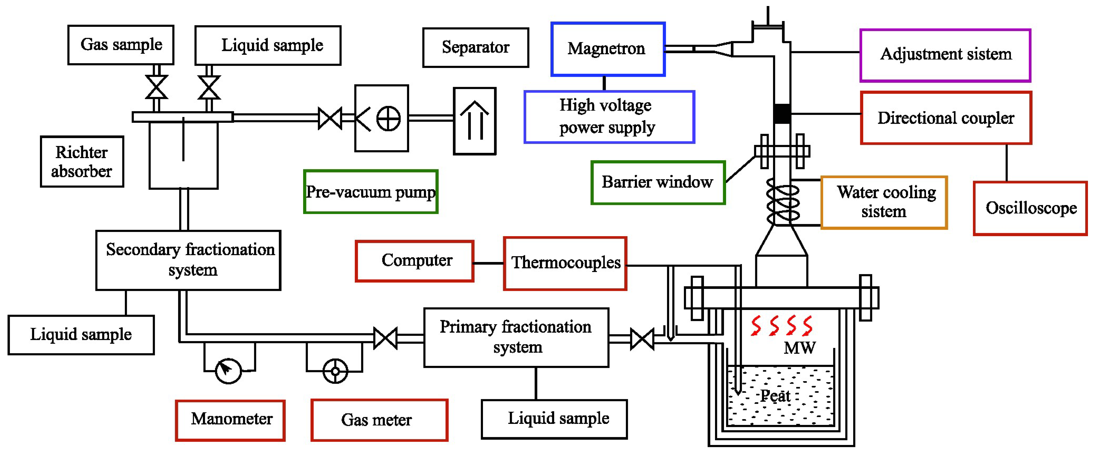
The schematic diagram of the designed complex for microwave pyrolysis of natural raw materials is shown in
Figure 1, the location of the installation components is depicted. The main structural elements of this complex are microwave sources (powerful narrow-band microwave generators) with a controlled high-voltage power supply, waveguide lines for the radiation transportation, a heat-insulated operating chamber (microwave reactor), raw material loading systems and unloading of solid residue, systems for pumping out reaction products combined with a system for fractionating liquid and gaseous products, as well as a complex management system (CMS) and a parameter control system (PCS). The objectives of this complex are the processing of various types of organic materials in different regimes, and obtaining a gaseous and liquid fraction, as well as a solid carbon residue. The purpose of this series of experiments was to study the features of microwave pyrolysis of peat, study the products of its processing, identify the features of the complex, and consider the possibility of scaling it up to process a larger mass of organic materials.
The developed complex allows operating in different regimes, including high-temperature pyrolysis (up to 1000 °C), as well as under conditions of both excessive and reduced pressure in the reactor, depending on the characteristics of the processed raw materials and the technologies used. At the same time, operation at a reduced pressure of about 0.1 atm and temperatures of ~250–300 °C in the so-called soft pyrolysis mode were chosen as optimal for the destruction of peat. This regime is suitable for deep destruction of materials with a large mass of organic fuel.
The developed complex operates in the following way [
35]. Organic raw materials (peat) are loaded into the heat-insulated operating chamber of the microwave reactor through the raw material loading system. After the loading is completed, the CMS system activates the system for pumping out reaction products, which at this stage removes air (reducing the amount of oxygen) and excess moisture by means of the backing pump. The use of such a pre-pumping system allows for the reduction of the energy and time spent on drying raw materials. To create the necessary pressure in the system and at the same time long and continuous operation in conditions of increased pollution by exhaust gases, a single-stage water ring pre-vacuum pump Pompetravaini TRMB 25–30 GH with a capacity of 30 m
3/h, a flow rate of the fluid of 8.3 L/s, and a maximum residual pressure of 33 mbar was chosen. The pressure was monitored and stabilized by the reaction parameter control system.
The PCS includes several thermocouples that provide temperature control in different parts of the reactor, a gas meter, and a pressure gauge. Thermocouples of the chromel–alumel (K-type) were selected, which are resistant to oxidation at high temperatures up to 1100 °C.
After pressure stabilization, the CMS turns on a controlled high-voltage power source and puts into operation one or more sources of microwave radiation (depending on their power and the amount of processed fuel). In devices focused on the average volume of processed raw materials (~3–5 kg), industrial kW power level magnetrons can be used as such sources. In the described series of experiments, we used the magnetron Samsung OM75S-21 having an operating frequency of 2.465 GHz and an output power (at the matched load) of 0.9 kW.
To enhance the volume and speed of processed organic raw materials, the number and power of microwave sources can be increased. For joint operation of several powerful sources, the configuration of radiation transmission lines is selected in such a way as to minimize the mutual influence of radiation sources, lessen reflection of radiation from the microwave reactor back to the source, and limit the maximum achievable values of the electric field in the electrodynamic system to eliminate high-frequency breakdown. If necessary, additional elements can be included in the transmission lines—directional couplers, circulators, etc., and decoupling between radiation sources in time or in polarization can also be carried out.
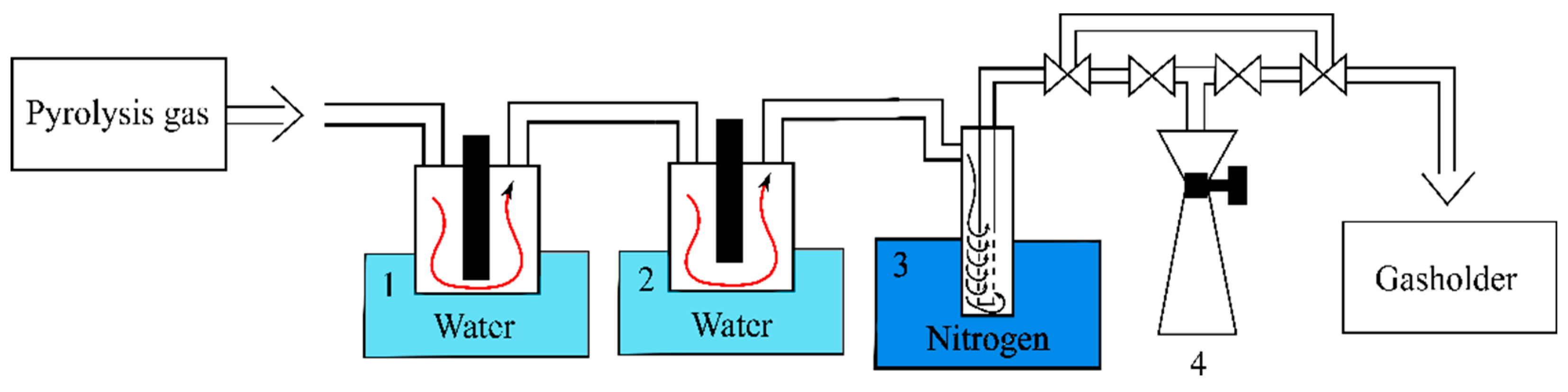
The radiation of magnetrons through the radiation transmission lines with radio-transparent barrier windows and adjustment systems enters the heat-insulated operating chamber of the microwave reactor and provides heating of the raw material to the reaction start temperature. When the raw material is heated, pyrolysis begins, and the released volatile reaction products start to be pumped out from the reactor volume and condense in the primary (1) and secondary (2) fractionation systems, as well as the Richter absorber (see
Figure 2). The primary and secondary fractionation systems represent a Tishchenko quartz flask with water as cooling liquid. In the first settler, heavier oily fractions are deposited, in the second—more volatile compounds. The remaining non-condensed pyrolysis gas is collected separately in a gas cylinder by means of a front pump. At the same time, during the pyrolysis process, the reaction products pumping system (4) allows sampling to control the quality of the reaction products and change the heating parameters (if necessary).
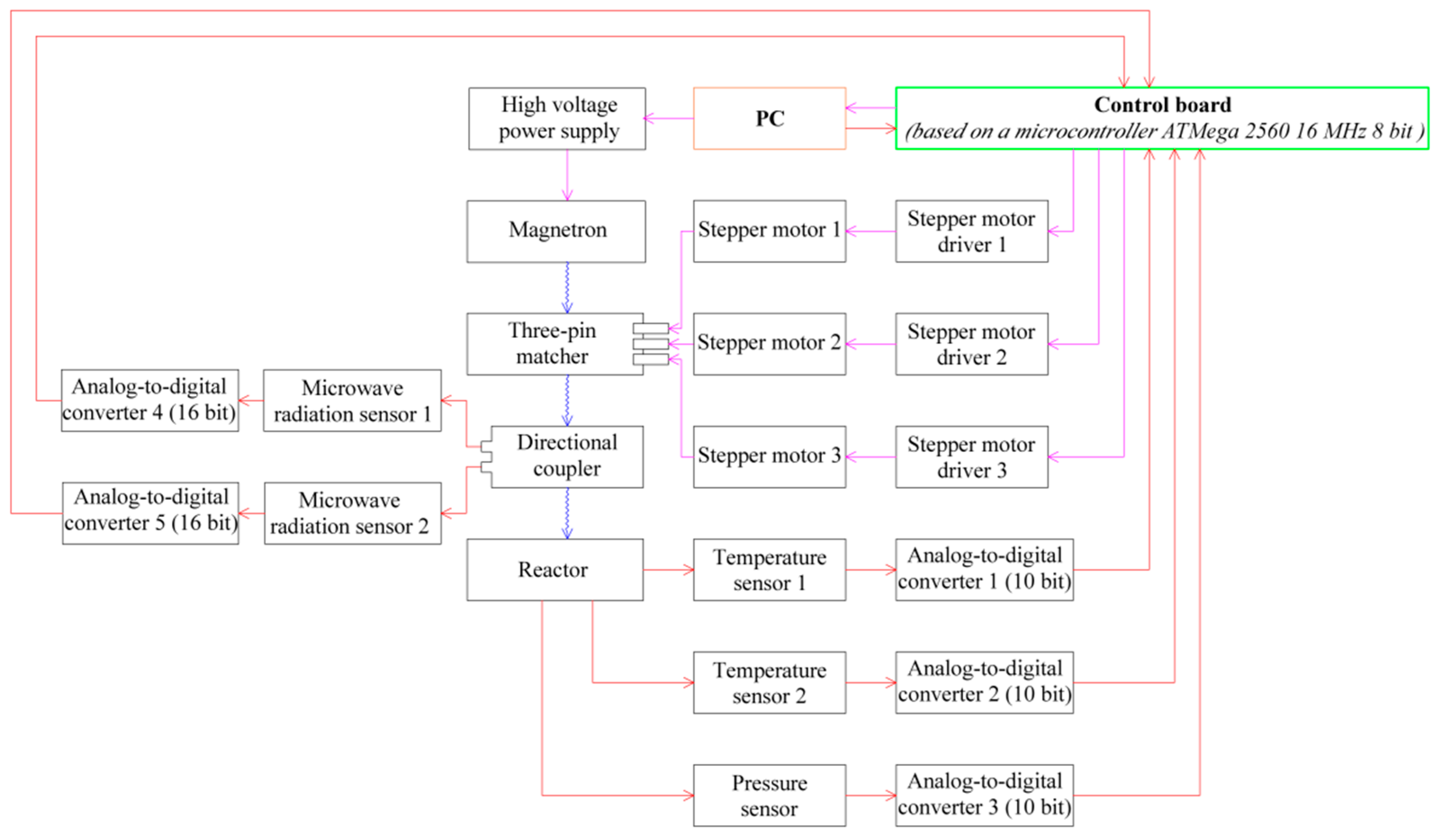
The automatic management system of the complex is shown in
Figure 3 (its components are illustrated in
Figure 1 by the red boxes) and includes a personal computer, a control board based on a microcontroller AT MEGA 2560, and a parameter control system. There is also a three-pin matcher in the transmission line. With the help of three rods extending to different depths inside the waveguide, the necessary level of reflection and phasing is provided to fully match the incident power with the load. The signal from the microwave radiation detector is fed to the amplifier, and then to the microprocessor unit. It processes and filters the incoming signal. Depending on the received signal, using the embedded software algorithm, a control signal is generated, which is fed to the stepper motor driver. The driver transmits a signal to the motor windings, and the radiation matcher pistons are regulated and adjusted.
After reaching the maximum reaction temperature monitored by the PCS, the CMS reduces the power until the operation of the magnetrons stops. After the completion of pyrolysis, the heat-insulated working chamber of the microwave reactor is cooled for some time, then the pressure equalizes with atmospheric pressure, and the carbonaceous residue is unloaded through the solid residue discharge system using the scraper mechanism.
The calibration of the adjustment system was carried out in preliminary experiments at various stages of the microwave pyrolysis process in accordance with changes in the absorption characteristics of the raw material. The waveguide transmission line of microwave radiation is equipped with radio-transparent barrier windows, which makes it possible to operate the operating chamber at a pressure below atmospheric pressure, as well as to efficiently pump out gaseous and condensable liquid (under standard conditions) pyrolysis products.
3. Design and Simulations of Electrodynamic System of Microwave Reactor
The electrodynamic system was designed to ensure efficient continuous operation of the microwave pyrolysis complex. The spatial distribution of the electromagnetic field in the microwave transmission system and the operating chamber was calculated using the Time Domain Solver (FDTD) of the CST Studio Suite package [
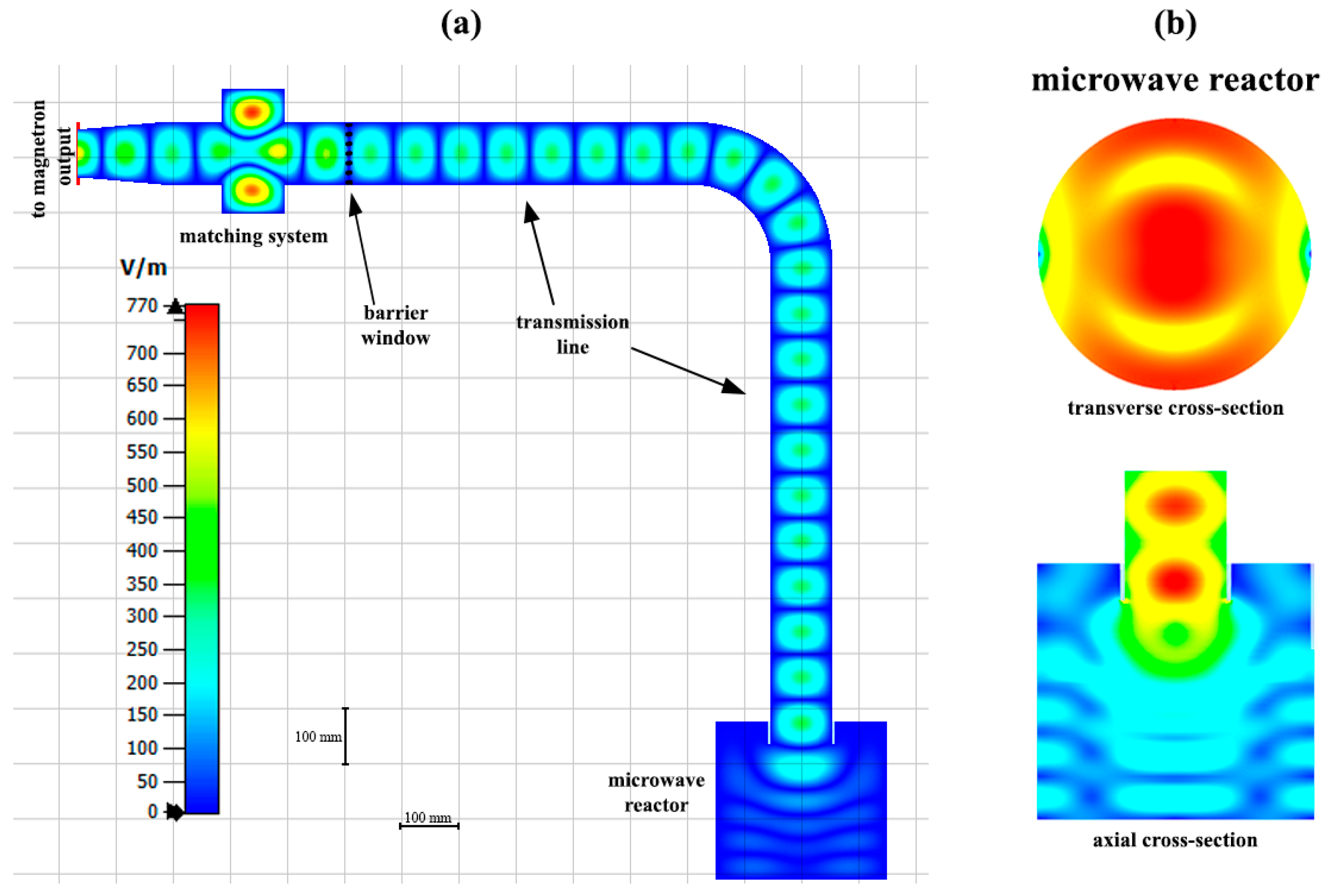
36]. The layout and parameters of the microwave transmission line were determined in the performed 3D simulations with different load volumes and absorption coefficients. Optimization of the reactor geometry was aimed to ensure the uniformity of the field distribution in the fuel volume and, thus, its uniform heating to provide the identity of the pyrolysis reaction for all mass fractions. The results of CST simulations of the optimized electrodynamic system of the complex, including the microwave transmission line and the operating chamber, are shown in
Figure 4. The design parameters of the reactor and the waveguide transmission line are given in
Table 1.
The relatively long length of the waveguides used in the transmission line with a natural temperature difference (or using a forced cooling system) is designed to ensure condensation of oily reaction products on their walls and, thus, minimize contamination of the barrier window by these products. The ingress of reaction products onto the barrier window is dangerous from the point of view of its additional heating due to increased absorption of microwave power, as a result of which it may be damaged. As well, additional reflections could appear, which contribute to an increase in the thermal load and the failure of the microwave source and the barrier window.
As discussed above, one of the main problems in the design of the microwave system of the complex is a significant change in the electrodynamic properties of organic materials (first of all, the microwave absorption) during the pyrolysis reaction. At the beginning of this process, peat has a relatively high humidity and thus a high absorption coefficient. Then, with the evaporation of wetness, the absorption of fuel drops sharply, and, as a result, the reflection from the loaded reactor can increase to a level of about −3 to −5 dB. This means that in non-optimized system up to half of the RF-power may be reflected and absorbed in the magnetron (which is obviously unacceptable from the point of view of its thermal load, breakdown restrictions, etc.). To provide the matching of the radiation source and the reactor, a waveguide system with two movable pistons was proposed and designed (shown in
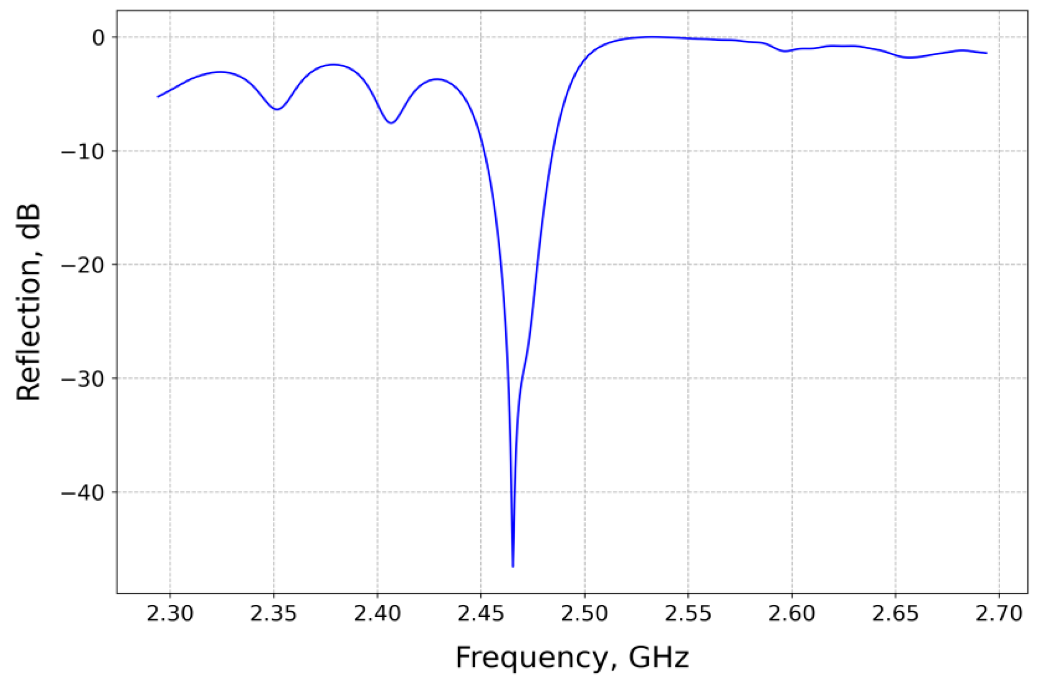
Figure 4), which is capable of compensating the reflection from the reactor in the level of down to −30 dB for the operating magnetron frequency, regardless of the phase of the reflected signal. Thus, the efficient operation of the magnetron in the optimal mode is ensured in a wide range of dielectric characteristics of the feedstock and the fraction of the loaded volume of the reactor. The calculated frequency dependence of the reflection coefficient for loading the reactor at 50% with raw materials, the dielectric characteristics of which are equal to the measured values for dried peat, is shown in
Figure 5. The positions of the pistons were chosen in such a way as to compensate for the reflection from the reactor at the operating frequency of the Samsung magnetron, which is 2.465 GHz. According to the simulations, the matching system made it possible to reduce the reflection below −10 dB by taking into account the magnetron bandwidth.
The uniformity of the field distribution in the reactor volume can be estimated by using relative standard deviation (RSD):
with the mean value of the dielectric heating
found at each point of the filled part of the reactor as
where
is standard deviation,
is operating frequency,
is imaginary part of the complex relative permittivity of the peat [
37],
is the permittivity of free space (vacuum),
is electric field strength. According to our simulations, the RSD for the designed reactor reaches 0.9. Thus, simulations demonstrated that by optimizing the size and configuration of the reactor and the waveguide transmission line, it was possible to achieve sufficiently high uniformity of the distribution of the electromagnetic field inside the operating chamber. Thus, the problem of uneven heating, which is present in various studies (see, for example [
38,
39]), can be solved.
4. Experimental Results and Discussions
Experiments on microwave pyrolysis of peat were carried out based on the prototype of the developed complex. The high-moor sphagnum peat of the Greko-Ushakovsky deposit was examined. As a result of the experiments, the yield of gaseous, liquid, and solid fractions was observed in the ratios of about 40%, 20%, and 40%, respectively.
In the conducted experiments, the CHNS analysis of the solid residue was made by elemental analyzer Vario EL Cube (Langenselbold, Germany, Elementar Analysen system). This procedure was made by the next steps. The mass of a sample was determined by analytical weight meter Toledo XS205DU (SpectraLab Scientific Inc., Markham, ON, Canada). Oxidizing analytic tube was filled with WO
3 (standard for the device). The oxygen was supplied to the oxidizing tube. After that, according to combustion products (CO
2, H
2O, SO
2, NO
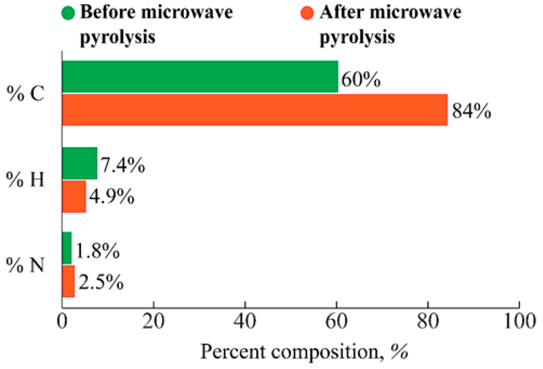
2), detected with thermal conductivity and infrared detection, the device’s program calculated the quantity of C, H, N, and S automatically. The mass content of carbon, hydrogen, and nitrogen in the solid product obtained as a result of elemental analysis of the solid product after microwave pyrolysis is shown in
Figure 6 without sulfur (it was lower than limit of detection—0.3%).
According to the results of previous studies [
38,
39] and the model experiments carried out, the applied conditions provide deep processing with a high yield of useful products due to longer thermal degradation of the feedstock and the optimal reaction rate in the operating reactor chamber. It is important to note that such a deep processing regime was obtained in a very wide range of loading volumes and was accompanied by intensive release of oily and gaseous fractions.
The high specific gas evolution during the pyrolysis reaction was demonstrated in the experiments. The pyrolysis gas containing methane can be used to generate thermal (with subsequent conversion to electrical) energy, as well as fuel for internal combustion engines. We can note that sufficiently intensive high-heat combustion was observed when these released gases were specially ignited at the outlet of the gasholder system of the reactor. Thus, the energy efficiency of microwave pyrolysis can be significantly increased when using recoverable energy from the combustion of released gases. Besides that, the pyrolysis gas can be used as a starting material for a chain of successive technological processes for the production of saturated acyclic hydrocarbons and synthetic polymers. After additional purification from H
2S and CO
2, the resulting gas can be used like a source of hydrogen [
40].
Liquid product (oily fraction) consists of peat resin and tar water. Peat tar is a complex mixture of chemical compounds, including monatomic and polyhydric phenols and phenol esters, waxes and paraffins, fatty acids, alcohols and oils, aldehydes, and ketones [
40]. It can serve as a feedstock for obtaining individual components.
Carbon residue (semi-coke) with a pure carbon content of up to 80% can be widely used in various areas of production, including the production of electrodes for the aluminum industry and ground electrodes, new allotropic modifications of carbon (nanotubes, fullerenes), and carbon fiber [
41]. It is worth mentioning that in the process of microwave destruction of peat, the pore size decreases on average, while the number of pores increases significantly. This is explained by the fact that due to the active gas release from the volume of the peat sample during microwave pyrolysis, the internal structure of the carbonaceous residue is disturbed. As a result, there is a noticeable increase in the area of the sorption surface of the sample, and macropores become the predominant type of pores in peat, through which macromolecules, for example, molecules of petroleum products, can easily penetrate into the peat structure. Therefore, this peat processing technology can also be used for the further production of a hydrophobic peat–mineral sorbent, which is effectively used for sorption of oil spills during the elimination of the consequences of man-made accidents.
5. Conclusions
Summarizing the conducted research, an energy-efficient complex for low-temperature microwave pyrolysis was elaborated. The complex’s design allows for uniform heating of raw materials, increasing the yield of the solid product, and decreasing process time at a temperature of 250 °C and above under low-pressure conditions.
The developed complex is capable of providing deep processing of organic fuels (in particular, peat) into oil-absorbing sorbents and other liquid and gaseous products that are in demand in the industry. The developed technology makes it possible to obtain raw materials for high-tech industrial production.
The proposed design of the installation allows for laboratory research of a wide range of organic materials, and with an increase in power and appropriate “scaling”, it can be used in petrochemistry, thermal power engineering, agriculture, and other industries.

 ,
, 


