Article

A Simulation Study of an Electro-Hydraulic Load-Sensitive Variable Pressure Margin Diverter Synchronous Drive System with Time-Varying Load Resistance

School of Mechanical Engineering, Guizhou University, Guiyang 550025, China
*
Author to whom correspondence should be addressed.
Processes 2024, 12(1), 170; https://doi.org/10.3390/pr12010170
Submission received: 16 September 2023 / Revised: 7 October 2023 / Accepted: 11 October 2023 / Published: 11 January 2024

Abstract

:
This study aims to address the problem of poor synchronous accuracy when facing a time-varying load in conventional load-sensitive synchronous drive systems. The new electro-hydraulic load-sensitive (EHLS) diverter synchronous drive system was proposed by combining the diverter valve and the EHLS synchronous drive system. The variable pressure margin compensation control was proposed to further improve the system’s synchronous control performance. Based on the system control strategy and component mathematical model, the simulation models of the EHLS, EHLS synchronous, and EHLS diverter synchronous drive systems were established using AMESim, respectively, and the synchronous control performance of the systems was obtained. The simulation results show that the EHLS drive system realized the primary functions of the load-sensitive system and could realize the variable load-sensitive pressure margin control. The EHLS synchronous drive system had poor synchronous control accuracy, but variable pressure compensation valve pressure margin control could be realized. The EHLS diverter synchronous drive system effectively improved the system’s synchronous control performance and diverter synchronous accuracy by variable pressure margin compensation control. The diverter system diverter error was reduced by 40.8%, and the diverter system after the compensation diverter error was reduced by 52.6% when the multi-way valves were fully opening. The system provides the solution for high-performance hydraulic synchronous drives under severe operating conditions.

1. Introduction

In recent years, the international community has attached increasing importance to developing the green economy, realizing “carbon neutrality” has become a significant development goal in the future [1,2]. To achieve zero emissions, off-road mobile machines and industrial hydraulics are also embracing the era of electrification, i.e., variable speed hydraulics will be the mainstay of future development.
The EHLS systems are typical applications of variable speed hydraulics technology, where the speed of the motor is controlled to match the pressure and flow of the system. Because the system has the advantages of fast response speed, strong self-adaptation, and smooth operation [3], it is widely used in electromechanical equipment. The development of electromechanical equipment technology has led to large-scale and heavy-duty developments [4,5]. This also increases the need for hydraulic synchronous drive technology for heavy loads. Hydraulic synchronous technology is used in various engineering applications [6,7,8]. High-precision, high-reliability, and high-efficiency hydraulic synchronous drives have been an important research topic and problem in hydraulics [9]. Hydraulic synchronous drive control consists of two primary forms of control: hydraulic synchronous closed-loop control and hydraulic synchronous open-loop control [10].
For hydraulic synchronous closed-loop control, scholars have carried out much research [11]. Ma [12] proposed the improved automatic anti-interference controller-improved particle swarm optimized position synchronous control method to solve the problem of insufficient platform synchronous control accuracy of the multi-hydraulic cylinder group platform of an anchor digging support robot. The results show that the method has better position tracking performance and shorter adjustment time, its stepping signal synchronous error was controlled within 5.0 mm, and the adjustment time was less than 2.55 s. Ding [13] proposed the robust output feedback position controller to solve the problem of the poor robustness of the conventional PID controller of the hydraulic support. The results show that the tracking accuracy of this controller was 47.2% and 30.6% higher than the conventional controller, respectively. Guo [14] proposed the synchronous controller based on improved sliding mode control for the hydraulic strut system. The results show that the controller could effectively reduce the synchronous error between the positions of two hydraulic struts and had better control performance than the PI and fuzzy PID controllers. Zhu [15] proposed the control method with dual closed-loop composite robustness to solve the performance deficiencies of the dual-pump dual-valve-controlled motor, such as poor output speed stability, low controllability, and difficulty in synchronous output management under external disturbances. The results show that the control method had high accuracy and robustness. Jing [16] proposed a load disturbance decoupling control method and developed a two-cylinder synchronous control system to meet the high precision control requirements of the system. The results show that the system’s robustness was improved. Therefore, most controllers were combined with optimization algorithms for hydraulic synchronous closed-loop control. Although it effectively improved the synchronous control performance of the system, the system was more complex and costly [17].
Hydraulic synchronous open-loop control is mainly based on the load-sensitive system. Hu [18] proposed the new pile-pressing hydraulic control system based on the design of the load-sensitive pump aimed at the problem of unsynchronous movement of pile-pressing cylinders during the pile pressing of a hydraulic static pile driver. The results show that the system had good synchronous control performance. Yang [19] used load-sensitive control for the two-cylinder synchronous drive to demand the high-efficiency, adjustable-speed, and high-precision synchronous drive system. The results reveal the primary factors and laws that affect the synchronous accuracy of the system. Wang [20] used the load-sensitive principle for the open-loop synchronous loop of the stent from the point of view of energy saving and high efficiency. The results show that this synchronous system’s displacement and velocity synchronous error were small. Therefore, the hydraulic synchronous open-loop control was mainly applied to the occasions where synchronous accuracy was not required. Although the hydraulic synchronous open-loop control is relative to the hydraulic synchronous closed-loop control, synchronous control accuracy is poor. The research of a new high-precision hydraulic synchronous open-loop control system is also significant, considering the cost.
Based on the above analysis, this study combined the EHLS synchronous drive system with the diverter valve diverter synchronous technology to construct a new EHLS diverter synchronous drive system. The contributions of this research are as follows:
(1)
The EHLS drive system was constructed, and variable load-sensitive pressure margin control was realized;
(2)
The diverter valve diverter synchronous technology was used in the EHLS synchronous drive system to construct the EHLS diverter synchronous drive system. It effectively improved the diverter synchronous accuracy of the system. However, it reduced the synchronous control performance of the system;
(3)
The solenoid pressure compensation valve replaced the conventional pressure compensation valve. The variable pressure compensation valve pressure margin control was realized;
(4)
The system synchronous control performance was ensured, and the system diverter synchronous accuracy was improved by variable pressure margin control.
This paper is structured as follows. Section 2 is the analysis of the system’s working principle. Section 3 is the analysis of the system control strategy. Section 4 is the analysis of the components’ mathematical model. Section 5 is system modeling and simulation. Section 6 is the discussion. Furthermore, Section 7 is the conclusion.

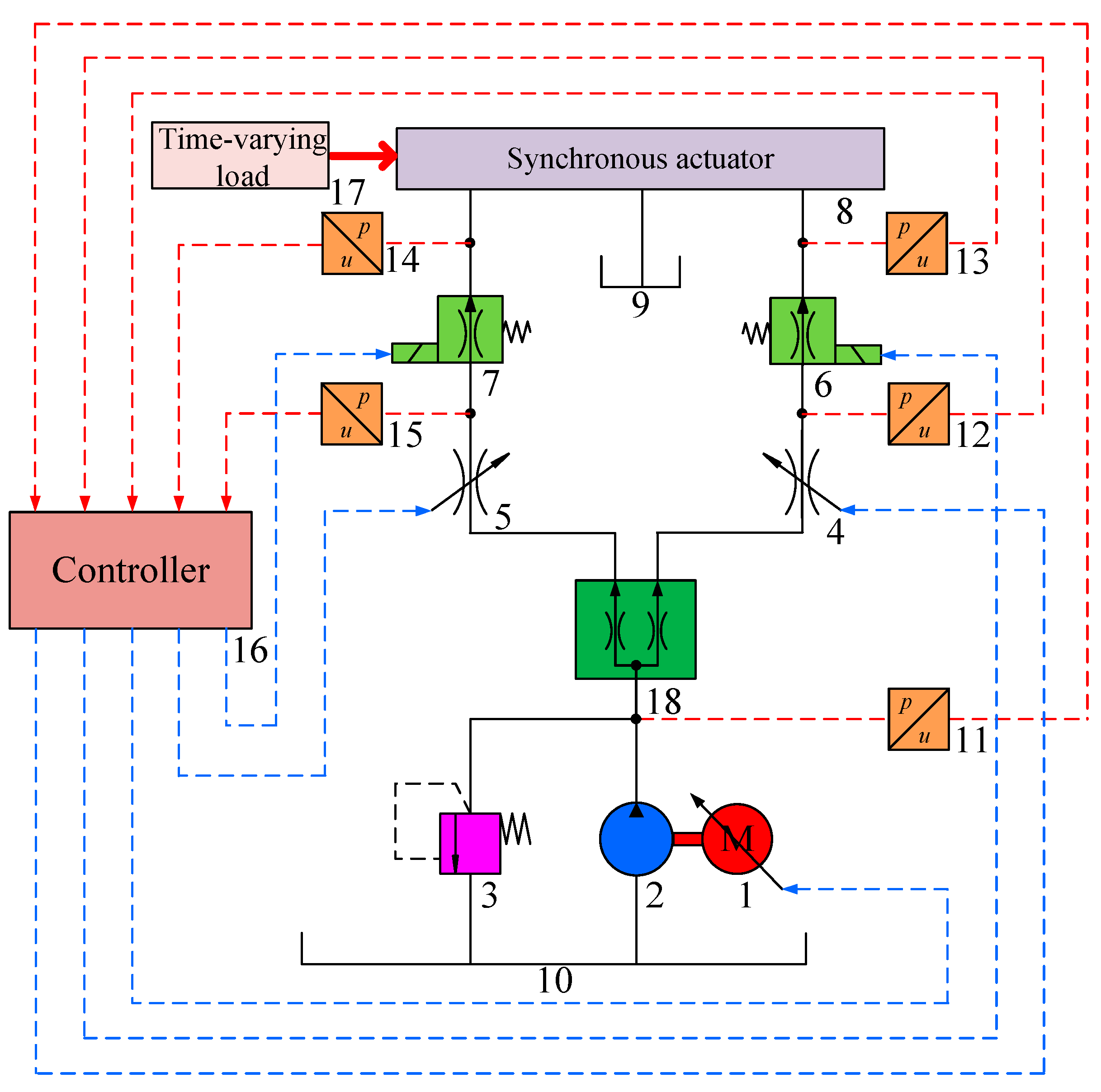
2. Analysis of the System’s Working Principle

This part analyzes the working principle and drawbacks of the conventional EHLS synchronous drive system. The new EHLS diverter synchronous drive system is proposed based on the conventional system, and the system’s working principle is analyzed.

2.1. Analysis of the Working Principle of the Conventional System

A conventional and typical EHLS synchronous drive system [21,22,23] is shown in Figure 1. The permanent magnet synchronous motor (PMSM), 1, drives a quantitative pump, 2, to generate high-pressure oil. The high-pressure oil enters the pressure compensation valves, 6 and 7, through the multi-way valves, 4 and 5, respectively, and the oil from the pressure compensation valves, 6 and 7, enters the synchronous actuator, 8, which causes the synchronous actuator, 8, to perform synchronous actions.
The multi-way valve openings are the same for load-sensitive synchronous drive systems during operation. The pressure compensation valves, 6 and 7, eliminate flow rate errors caused by static load variation. However, the load is mostly time-varying when the synchronous actuator, 8, performs synchronous actions. The pressure compensation valves are slow to respond and do not eliminate time-varying loads. Furthermore, the system uses pressure feedback closed-loop control to control the system pressure and flow rate. When the load changes, it will inevitably cause the system pressure and flow rate to change, reducing the system’s synchronous accuracy. When the actuator requires high synchronous accuracy, it is difficult for the system to meet the requirements. Therefore, it is necessary to improve the system’s synchronous accuracy.

2.2. Analysis of the Working Principle of the New System

The diverter valve diverter synchronous technology is introduced into the typical EHLS synchronous drive system to improve the synchronous accuracy of the conventional drive system when facing a time-varying load. The new EHLS diverter synchronous drive system is constructed, as shown in Figure 2. The system is compared with the conventional system. The diverter valve, 18, is added between the quantitative pump, 2, and the multi-way valves, 4 and 5. It can improve the system diverter synchronous accuracy. A solenoid pressure compensation valve replaces the conventional pressure compensation valve. It can improve the response speed of the pressure compensation valve and reduce the impact of time-varying load on the synchronous system. When the system load is a time-varying load, the system can effectively improve the synchronous accuracy of the system through the diverter effect of the diverter valve and the compensation effect of the solenoid pressure compensation valve.

3. Analysis of System Control Strategy

This section analyzes the variable speed control, the variable load-sensitive pressure margin control, and the variable pressure compensation valve pressure margin control.

3.1. Variable Speed Control

The system utilizes a combination of the quantitative pump and the PMSM. The PMSM speed is adjusted to control the quantitative pump outlet pressure and flow rate using pressure feedback closed-loop control.
The quantitative pump outlet target pressure can be described as [24]:
p p = p M a x + p L s
where p p is the target pressure of the quantitative pump, Pa; p M a x is the maximum load pressure, Pa; and p L s is the load-sensitive preset pressure margin, Pa.
The quantitative pump outlet pressure error can be described as [24]:
e p = p p p p
where e p is the quantitative pump outlet pressure error, Pa, and p p is the actual pressure of the quantitative pump outlet, Pa.
The PMSM target torque can be obtained using e p as the PID controller inlet, and then the PMSM target torque can be described as [24]:
T e p = k p e p + k i e p d t + k d e ˙ p
where T e p is the PMSM target torque, N·m; k p is the scaling factor; k i is the integration coefficient; and k d is the differentiation coefficient.
The PMSM target speed can be described as [24]:
n r e f = f e p = 9550 P T e p
where n r e f is the PMSM target speed, rev/min, and P is the PMSM rated power, kW.
It can be seen in Equations (1)–(4) that when p M a x changes dynamically to maintain p L s , the PMSM target speed will also change to dynamically regulate the quantitative pump’s outlet pressure and flow rate to bring the system to a new equilibrium state.

3.2. Variable Load-Sensitive Pressure Margin Control

Based on the analysis in Section 3.1, it can be seen that when p L s is changed, the system can maintain the new p L s through the pressure feedback closed-loop control. Therefore, the system can realize variable p L s control.
For the EHLS synchronous drive system, synchronous performance can be reflected by the flow rate of each branch.
The flow rate through the multi-way valve, 1, can be described as:
Q 1 = C d w x 1 2 ( p L s p d ) ρ = C d w x 1 2 ( p 1 ) ρ
where Q 1 is the flow rate through the multi-way valve, 1, m3/s; C d is the flow coefficient; w is the area gradient, m; x 1 is the spool displacement of the multi-way valve, 1, m; p d is the preset pressure margin of the pressure compensation valve, Pa; ρ is the oil density, kg/m3; and p 1 is the pressure difference before and after the multi-way valve, 1, Pa.
The flow rate through the multi-way valve, 2, can be described as:
Q 2 = C d w x 2 2 ( p L s p d ) ρ = C d w x 2 2 ( p 2 ) ρ
where Q 2 is the flow rate through the multi-way valve, 2, m3/s; x 2 is the spool displacement of the multi-way valve, 2, m; and p 2 is the pressure difference before and after the multi-way valve, 2, Pa.
Ib Equations (5) and (6), Q 1 and Q 2 vary when p L s varies. Therefore, the variable p L s control can regulate the system flow rate.
Normally, the system multi-way valve openings are equal, i.e., x 1 = x 2 . Therefore, theoretically, Q 1 = Q 2 , i.e., the flow rate of each branch is equal. However, when time-varying loads exist in each system branch, it is difficult for the system to reach equilibrium quickly, resulting in the actual p 1 p 2 in each branch of the system, which results in Q 1 Q 2 , i.e., the flow rate in each branch is not equal, causing the system diverter error.
For the EHLS diverter synchronous drive system, the diverter valve is added to the circuit, resulting in a system pressure loss.
The flow rate through the multi-way valve, 1, can be described as:
Q 11 = C d w x 1 2 ( p L s p s 1 p d ) ρ = C d w x 1 2 ( p 11 ) ρ
where Q 11 is the flow rate through the multi-way valve, 1, m3/s; p s 1 is the branch 1 diverter valve pressure drop, Pa; and p 11 is the pressure difference before and after the multi-way valve, 1, Pa.
The flow rate through the multi-way valve, 2, can be described as:
Q 22 = C d w x 2 2 ( p L s p s 2 p d ) ρ = C d w x 2 2 ( p 22 ) ρ
where Q 22 is the flow rate through the multi-way valve, 2, m3/s; p s 2 is the branch 2 diverter valve pressure drop, Pa; and p 22 is the pressure difference before and after the multi-way valve, 2, Pa.
It can be seen in Equations (7) and (8) that since the opening of the multi-way valve is equal, i.e., x 1 = x 2 . It must satisfy p 11 = p 22 to realize Q 11 = Q 22 . When there is a time-varying load in each branch of the system due to the diverter effect of the diverter valve, p s 1 and p s 2 are compensated for the system so that p 11 = p 22 , realizing Q 11 = Q 22 . Thus, the system diverter synchronous accuracy is improved.
When the opening of the multi-way valve increases, the system flow rate increases, while the throttling effect of the diverter valve is strengthened, resulting in an increase in p s 1 and p s 2 , which reduces Q 11 and Q 22 . It is necessary to satisfy Q 1 = Q 2 = Q 11 = Q 22 to ensure the synchronous control performance of the system, as is shown in Equations (5)–(8), i.e., it is necessary to satisfy p 1 = p 2 = p 11 = p 22 . Therefore, p L s and p d must be changed so that the system realizes p 1 = p 2 = p 11 = p 22 , i.e., the system must undergo variable pressure margin control.

3.3. Variable Pressure Compensation Valve Pressure Margin Control

The solenoid pressure compensation valve replaces the conventional pressure compensation valve to realize the variable pressure compensation valve pressure margin control.
The actual differential pressure of the solenoid pressure compensation valve can be described as [24]:
e p d = p n p M a x
where e p d is the actual differential pressure of the solenoid pressure compensation valve, Pa, and p n is the pressure before the solenoid pressure compensation valve, Pa.
The pressure compensation valve preset differential pressure error can be described as [24]:
e p d m = p d e p d
where e p d m is the preset differential pressure error of the solenoid pressure compensation valve, Pa.
The control current of the solenoid pressure compensation valve can be described as [24]:
i c = k p e p d m + k i e p d m d t + k d e ˙ p d m
where i c is the control current of the solenoid pressure compensation valve, A.
It can be seen in Equations (9)–(11) that when p M a x is dynamically changed, the solenoid pressure compensation valve control current will also be changed to maintain p d so that the system reaches a new equilibrium state. When p d is changed, the system can maintain the new p d by pressure feedback closed-loop control. Therefore, the system can realize variable p d control.
Based on the analysis in Section 3.1, Section 3.2 and Section 3.3, a block diagram of the system control strategy can be obtained, as shown in Figure 3. Through the pressure feedback closed-loop control, the system can realize variable load-sensitive and variable pressure compensation valve pressure margin control to compensate for the pressure loss caused by the diverter valve. Under the premise of ensuring the synchronous control performance of the system, the diverter of synchronous accuracy of the system is improved.

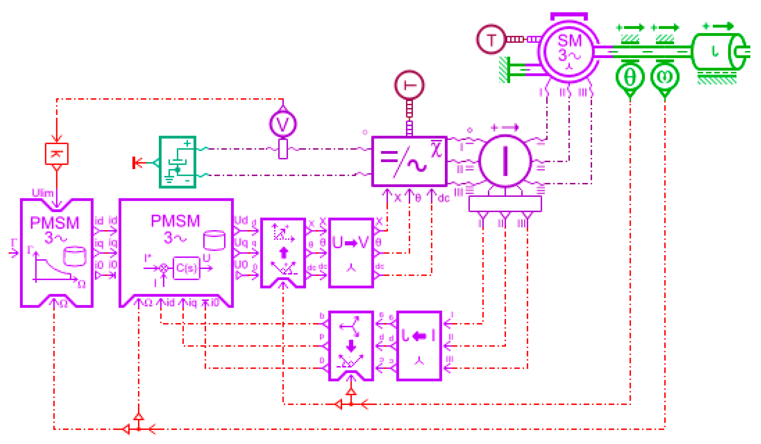
4. Analysis of Components’ Mathematical Model

This part analyzes the PMSM, solenoid pressure compensation valve, and diverter valve mathematical model and establishes the components simulation model based on the mathematical model.

4.1. PMSM Mathematical Model

The PMSM consists of a controller, inverter, motor, and sensors. In order to facilitate the analysis, the assumptions are simplified during the derivation of the mathematical model [25]. Based on the assumptions, its equivalent schematic diagram can be obtained, as shown in Figure 4.
The stator voltage equation of the PMSM can be described as [25]:
u d u q = R s ω e L q ω e L d R s i d i q + d d t ψ d ψ q + 0 ω e ψ f
where u d and u q are the dp-axis voltages, V; i d and i q are the dp-axis currents, A; ψ d and ψ q are the dp-axis magnetic chains, Wb; and ω e is the rotor angular velocity, rad/s.
The magnetic chain equation of the PMSM can be described as [25]:
ψ d ψ q = L d 0 0 L d i d i q + ψ f 0
The electromagnetic torque equation of the PMSM can be described as [25]:
T 2 e = 3 2 p 2 n ψ f i q + L d L q i d i q
where T 2 e is the motor output torque, N∙m, and p 2 n is the number of motor pole pairs.
Equation (14) consists of two terms. The first term, ψ f i q , is the excitation torque; the electromagnetic torque formed by the interaction of the excitation field of the permanent magnet with the stator current. The second term, ( L d L q ) i d i q , is the reluctance torque; the electromagnetic torque formed by the rotor convex polarity effect. The reluctance torque is inherent to the convex polarity PMSM. There is no formation of reluctance torque for the hidden polarity PMSM due to L d L q . Therefore, the linear equation of the electromagnetic torque can be described as [25]:
T 2 e = 3 2 p n ψ f i q
The PMSM equations of motion can be described as [25]:
T 3 e = T L + J d ω d t + B ω
where T 3 e is the motor outlet torque, N∙m; T L is the load torque, N∙m; J is the equivalent moment of inertia converted to the motor shaft, kg∙m2; B is the coefficient of viscous friction; and ω is the mechanical angular velocity of the motor outlet shaft, rad/s.
In Equation (16), B ω is the loss torque of the motor motion and J d ω d t is the acceleration torque of the whole motor system. Neglecting the damping efficiency and simplifying Equation (16), we obtain:
J d ω d t = T 3 e T L
The control of the PMSM speed control system can be categorized into variable voltage and frequency, direct torque, speed without a sensor, and vector control [26]. This research uses a representative control method, the i d r e f = 0 control in a vector. Based on the above analysis, the AMESim establishes the simulation model, as shown in Figure 5.

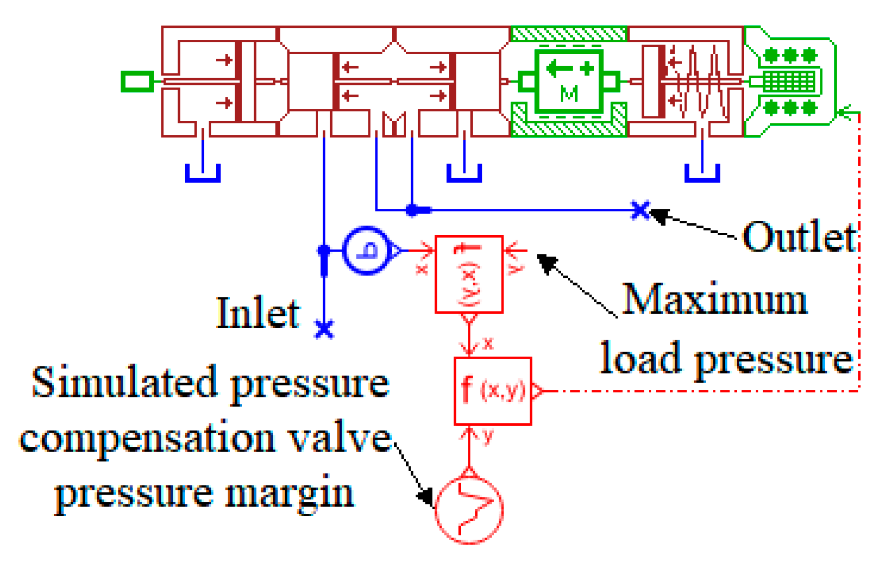
4.2. Mathematical Modeling of Solenoid Pressure Compensation Valve

The system pressure is controlled by the spool displacement during the operation of the solenoid pressure compensation valve. The differential equation of the spool motion of the pressure compensation valve can be described as follows [27]:
F C F K = M C d 2 x C d t 2 + B C d x C d t + K S C x C
where F C is the electromagnetic force, N; F K is the preset spring force, N; M C is the spool mass, kg; B C is the viscous damping coefficient; K S C is the spring stiffness, N/m; and x C is the spool displacement, m.
For the maximum load branch, the pressure before the solenoid pressure compensation valve can be described as [27]:
p C 1 = p d + p m a x
where p C 1 is the pressure before the solenoid pressure compensation valve, Pa.
For the other branch, the pressure before the solenoid pressure compensation valve can be described as [27]:
p C 2 = p d + p L + p C
where p C 2 is the pressure before the solenoid pressure compensation valve, Pa; p L is the load pressure, Pa; and p C is the solenoid pressure compensation valve compensating pressure, Pa.
When the load pressure p m a x and p L change dynamically, F C changes with them. It can be seen in Equations (18)–(20) that due to the compensating effect of the solenoid pressure compensation valve, i.e., p C is compensated in the less loaded branch, making p C 1 = p C 2 . It makes the pressure difference before and after the multi-way valves, 1 and 2, equal, making the flow rate through the multi-way valves, 1 and 2, equal.
Based on the above analysis, the AMESim hydraulic, signal, and HCD library are used to establish the simulation model, as shown in Figure 6, and the simulation parameters in Table 1.

4.3. Mathematical Modeling of the Diverter Valve

The diverter valve is used as the system flow distribution element, ignoring the secondary influences [28], and its mechanical simplified model is shown in Figure 7, in which the throttle ports are all used as thin-walled small holes.
Based on the flow equations for the cylindrical slide valve opening and throttle port, the flow continuity equations for each volume chamber, and the spool dynamics equations, the dynamic mathematical model of the diverter valve can be described as [29]:
Q a = c π d c x m + x 2 ρ p c p a
Q b = c π d c ( x m x ) 2 ρ ( p d p b )
Q c = 1 4 c π d a 2 2 ρ p s p c
Q d = 1 4 c π d b 2 2 ρ p s p d
Q c Q a 1 4 π d c 2 d x d t V 1 β e d p c d t = 0
Q d Q b + 1 4 π d c 2 d x d t V 2 β e d p d d t = 0
Q s Q c Q d V 0 β e d p s d t = 0
M d 2 x d t 2 + B v d x d t + k 1 x m + x k 2 x m x = 1 4 π d c 2 ( p c p d )
where Q a and Q b are the left and right outlet port flow rate, m3/s; Q c and Q d are the outlet flow rate of the left and right cavity fixed throttling ports, m3/s; Q s is the inlet port flow rate, m3/s; c is the throttle port flow coefficient, c = c 1 = c 2 ; d a and d b are the equivalent diameters of the fixed throttling holes of the left and right valve cavities, m; d c is the diameter of the valve seat bore, m; p a and p b are the left and right output port pressures, Pa; p c and p d are the outlet pressure of the left and right cavity fixed throttling port, Pa; p s is the inlet port pressure, Pa; x m is the pre-opening of the variable throttle port when the spool is in the middle position, m; x is the pre-opening volume of the convenience throttle port when the spool is in the neutral position, m; V 0 is the inlet cavity volume, m3; V 1 and V 2 are the left and right cavity volumes of the spool, m3; β e is the integrated modulus of elasticity of the system; B v is the viscous damping of the liquid; M is the mass of the spool, kg; and k 1 and k 2 are the centering spring stiffnesses.
The steady-state characteristic equation of the diverter valve can be obtained by making d p c d t = d p d d t = d p s d t = d 2 x d t 2 = d x d t = 0 .
The system diverter error can be described as:
η = 2 Q a Q b Q s × 100 %
where η is the system diverter error, %.
Based on the above analysis, the AMESim hydraulic, 2D mechanical, and HCD libraries are used to establish the simulation model, as shown in Figure 8, and the simulation parameters in Table 2.

5. System Modeling and Simulation

This part establishes the simulation models of the EHLS, EHLS synchronous, and EHLS diverter synchronous drive systems and analyzes the system characteristics.

5.1. The EHLS Drive System

Based on the analysis in Section 3.1, Section 3.2, and Section 4.1, the simulation model can be established using the AMESim hydraulic, 1D mechanical, and signal libraries, as shown in Figure 9. The proportional relief valve simulates the load, which is set to ( 5 sin 2 π t + 20 )   MPa. The proportional throttle valve simulates the multi-way valve. The main simulation parameters of the system are set, as shown in Table 3. The simulation time is set to 10 s, in which 0 to 2 s multi-way valve opening is 20%, 2 s to 4 s multi-way valve opening is 40%, 4 s to 6 s multi-way valve opening is 60%, 6 s to 8 s multi-way valve opening is 80%, and 8 s to 10 s multi-way valve opening is 100%. Subsequent studies will analyze the system characteristics based on this simulation time. The system characteristics are discussed for simulated load-sensitive pressure margins of 2 MPa and 3 MPa, respectively.
As shown in Figure 10, the system pressure, flow, and opening curves are simulated when the load-sensitive pressure margin is 2 MPa. The outlet pressure of the quantitative pump changes, and the pressure difference before and after the multi-way valve is maintained at 2 MPa when the simulated load pressure changes. The flow rate through the multi-way valve increases when the opening of the multi-way valve increases. The system flow rate is independent of the load pressure and proportional to the opening of the multi-way valve. Therefore, the system realizes the primary function of the load-sensitive system.
As shown in Figure 11, the system pressure, flow, and opening curves are simulated when the load-sensitive pressure margin is 3 MPa. The quantitative pump outlet pressure changes, and the pressure difference before and after the multi-way valve is maintained at 3 MPa when the simulated load pressure changes. The flow rate through the multi-way valve increases when the multi-way valve opening increases. As the simulated load-sensitive pressure margin increases, the flow rate through the multi-way valve increases, combined with the analysis in Figure 10. Therefore, the system can realize variable load-sensitive pressure margin control to regulate the differential pressure and flow rate before and after the multi-way valve.
Based on the above analysis, the system realizes the primary functions of the load-sensitive system and can realize the variable load-sensitive pressure margin control to regulate the differential pressure and flow before and after the multi-way valve.

5.2. The EHLS Synchronous Drive System

Based on the analysis in Section 3.2 and combined with the analysis in Section 5.1, a simulation model can be established, as shown in Figure 12. The system consists of two synchronous branches: load 1 is set to ( 5 sin 4 π t + 15 )   MPa and load 2 is set to ( 5 cos 4 π t + 15 ) MPa. The subsequent study will analyze the system characteristics based on this load. The system characteristics are discussed for simulated solenoid pressure compensation valves with 1 MPa and 1.5 MPa pressure margins, respectively.
As shown in Figure 13, the system pressure, flow rate, and opening curves are shown when the solenoid pressure compensation valve margin is 1 MPa. The pressure difference before and after the multi-way valves, 1 and 2, is maintained at about 1 MPa when the simulated load pressures, 1 and 2, change alternately. The flow rate of the multi-way valves, 1 and 2, gradually increases, and the flow rate error becomes larger and larger as the opening of the multi-way valve increases. Therefore, the system has poor synchronous control accuracy.
As shown in Figure 14, the system pressure, flow rate, and opening curves are shown when the solenoid pressure compensation valve margin is 1.5 MPa. The pressure difference between the front and rear of the multiplex valves, 1 and 2, is maintained at about 0.5 MPa when the simulated load pressures, 1 and 2, change alternately. The flow rate of the multi-way valves, 1 and 2, gradually increases, and the flow rate error becomes larger and larger as the opening of the multi-way valve increases. As the solenoid pressure compensation valve margin increases, the flow rate through the multi-way valve decreases, combined with the analysis in Figure 13. The differential pressure error before and after the multi-way valves, 1 and 2, is getting smaller and smaller, and the system flow error is getting smaller and smaller. Therefore, the system can realize variable pressure compensation valve pressure margin control to regulate the differential pressure and flow before and after the multi-way valve.
Based on the above analysis, the system has poor synchronous control accuracy. It can realize variable solenoid pressure compensation valve pressure margin control to regulate the pressure difference and flow rate before and after the multi-way valve.

5.3. The EHLS Diverter Synchronous Drive System

Based on the analysis in Section 3 and combined with the analysis in Section 5.2, the simulation model can be established, as shown in Figure 15 and Figure 16. The diverter valve is added to the EHLS synchronous drive system to construct an EHLS diverter synchronous drive system. The system characteristics are analyzed before and after the variable pressure margin control.
As shown in Figure 17, the system pressure, flow, and opening curves before the variable pressure margin are shown. In the diverter system, as the opening of the multi-way valves increases, the flow rate through the multi-way valve increases. The throttling effect of the diverter valve is enhanced, resulting in a decrease in the pressure difference between before and after the multi-way valves, 1 and 2, compared to the synchronous system, which leads to a decrease in the flow rate through the multi-way valves, 1 and 2. As a result, the synchronous control performance of the system decreases. The differential pressure and flow rate before and after the multi-way valve can be adjusted by variable pressure margin control to improve the synchronous control performance of the system combined with the analysis in Section 5.1 and Section 5.2.
As shown in Figure 18, the system pressure and opening curves after the variable pressure margin are shown. In the diverter system, after the variable pressure margin control, compared with the before compensation period, the pressure difference before and after the multi-way valve, 1 and 2, increases significantly as the opening of the multi-way valve increases, and it is consistent with the synchronous system, which maintains the pressure difference at about 1 MPa.
As shown in Figure 19, the system flow and opening curves after the variable pressure margin are shown. In the diverter system, after the variable pressure margin control, compared with the before compensation period, the flow rate of the multi-way valve, 1 and 2, increases significantly as the opening of the multi-way valve increases and is consistent with the synchronous system. Therefore, the diverter system effectively improves the synchronous control performance of the system after compensation by variable pressure margin.
As shown in Figure 20, the system diverter error and opening curves are shown. The diverter error of the conventional, the diverter, and the diverter compensation systems gradually increases as the opening of the multi-way valve increases. In particular, the maximum diverter error of the conventional system is 61%, the diverter system is 20.2%, and the diverter system after compensation is 8.4% when the diverter valve is fully opening. Therefore, the diverter system diverter error is reduced by 40.8%, and the diverter system after compensation diverter error is reduced by 52.6%. The diverter system after compensation effectively improves the synchronous accuracy of the system by variable pressure margin compensation control.
Based on the above analysis, the diverter system effectively improves the synchronous control performance of the system by variable pressure margin compensation control. The diverter system diverter error is reduced by 40.8%, and the diverter error of the diverter system after compensation is reduced by 52.6% when the multi-way valve is fully opening. The diverter system after compensation effectively improves the synchronous accuracy of the system by the variable pressure margin compensation control. In summary, the system performance can be compared, as shown in Table 4.

6. Discussion

The system working principle, control strategy, and component mathematical model are analyzed. Based on this partial analysis, the EHLS, EHLS synchronous, and EHLS diverter synchronous drive system simulation models were established, respectively, and the system characteristics were analyzed. The simulation results show that the EHLS diverter synchronous drive system effectively improves the diverter synchronous accuracy of the system. It guarantees the system’s synchronous control performance compared with the conventional EHLS synchronous drive system through the variable pressure margin compensation control.
This EHLS diverter synchronous drive system and diverter valve combine an EHLS synchronous drive system. They effectively improve the diverter synchronous accuracy of the system through the diverter valve diverter effect and variable pressure margin control. The system is suitable for the actuator action, the system of each branch of the time-varying load, and the actuator synchronous accuracy requirements of high occasions. The variable pressure margin control system can ensure that the system still has a high diverter synchronous accuracy when the multi-way valve has different opening degrees.

7. Conclusions

Based on the above, the following conclusions can be obtained:
  • The EHLS drive system realizes the primary function of the load-sensitive system. It can realize the variable load-sensitive pressure margin control to regulate the differential pressure and flow rate before and after the multi-way valve;
  • The EHLS synchronous drive system has poor synchronous control accuracy. It can realize variable pressure compensation valve pressure margin control to regulate the differential pressure and flow before and after the multi-way valve;
  • The EHLS diverter synchronous drive system effectively improves the synchronous control performance of the system through variable pressure margin compensation control. The diverter system diverter error is reduced by 40.8%, and the diverter compensation system diverter error is reduced by 52.6% when the multi-way valve is fully opened. After the variable pressure margin compensation control, the diverter system effectively improves the diverter synchronous accuracy;
  • The system provides a high-performance hydraulic synchronous drive solution under severe working conditions.

Author Contributions

Conceptualization and methodology, W.D.; software, validation, and writing—original draft preparation, W.D., H.M. and Y.L. (Yu Luo); writing—review and editing and supervision, project administration, and funding acquisition, Y.L. (Yu Luo) and Y.L. (Yanlei Luo). All authors have read and agreed to the published version of the manuscript.

Funding

This work is supported by the National Natural Science Foundation of China Project (52265007) and the Science and Technology Project of Guizhou Province (Qiankehe Foundation-ZK (2022) General 087).

Data Availability Statement

Data are contained within the article.

Acknowledgments

We would like to express our gratitude to the anonymous reviewers and friends who helped us in the process of completing this paper.

Conflicts of Interest

The authors declare no conflict of interest.

References

  1. Wang, H. Analysis of Current Situation and Prospect of Electrification of Construction Machinery. Constr. Mach. Dig. 2022, 3, 23–25. [Google Scholar]
  2. Nie, H.; Shen, W. Research on Popularization and Application of Electric Construction Machinery. Constr. Mech. 2022, 43, 19–21. [Google Scholar]
  3. Fu, S.; Lin, T.; Wang, L.; Miao, C. Load Sensitive System Based on Variable Speed Control. China J. Highw. Transp. 2020, 33, 189–196. [Google Scholar]
  4. Zuo, D.; Qian, L.; Yang, T.; Cui, X.; Luo, Q. Coupling Leveling Control Based on Fuzzy PID for Synchronous Loading System of Load-Bearing Test Bed. Chin. J. Electron. 2017, 26, 1206–1212. [Google Scholar] [CrossRef]
  5. He, B.; Zhao, C.; Wang, H.; Chang, X.; Wen, B. Dynamics of synchronization for four hydraulic motors in a vibrating pile driver system. Adv. Mech. Eng. 2016, 8, 1–15. [Google Scholar] [CrossRef]
  6. Liu, Z.; Gao, Q.; Yu, C.; Li, X.Y.; Guan, W.L.; Deng, G.F. Collaborative Synchronization Digital Control for Double Hydraulic Cylinders. Adv. Mech. Eng. 2014, 6 Pt 9, 371403. [Google Scholar] [CrossRef]
  7. Wang, X.; Liao, R.; Shi, C.; Wang, S. Linear extended state observer-based motion synchronization control for hybrid actuation system of more electric aircraft. Sensors 2017, 17, 2444. [Google Scholar] [CrossRef] [PubMed]
  8. Rehman, U.; Wang, X.; Hameed, Z.; Gul, M.Y. Motion Synchronization Control for a Large Civil Aircraft’s Hybrid Actuation System Using Fuzzy Logic-Based Control Techniques. Mathematics 2023, 11, 1576. [Google Scholar] [CrossRef]
  9. Ding, H.; Liu, Y.; Zhao, J.; Chao, C. Research on principle of variable speed flow dividing synchronous drive in load-sensing under time-varying bias loads. J. Huazhong Univ. Sci. Technol. (Nat. Sci. Ed.) 2021, 49, 62–67. [Google Scholar]
  10. Ding, H.; Liu, Y.; Zhao, Y. A new hydraulic synchronous scheme in open-loop control: Load-sensing synchronous control. Meas. Control 2020, 53, 119–125. [Google Scholar] [CrossRef]
  11. Li, R.; Yuan, W.; Ding, X.; Xu, J.; Sun, Q.; Zhang, Y. Review of Research and Development of Hydraulic Synchronous Control System. Processes 2023, 11, 981. [Google Scholar] [CrossRef]
  12. Ma, T.; Guo, X.; Su, G.; Deng, H.; Yang, T. Research on Synchronous Control of Active Disturbance Rejection Position of Multiple Hydraulic Cylinders of Digging-Anchor-Support Robot. Sensors 2023, 23, 4092. [Google Scholar] [CrossRef] [PubMed]
  13. Ding, H.; Wang, Y.; Zhang, H. Robust Output Feedback Position Control of Hydraulic Support with Neural Network Compensator. Actuators 2023, 12, 263. [Google Scholar] [CrossRef]
  14. Guo, Y.; Zhang, Z.; Liu, Q.; Nie, Z.; Gong, D.W. Decoupling-based adaptive sliding-mode synchro-position control for a dual-cylinder driven hydraulic support with different pipelines. ISA Trans. 2021, 123, 357–371. [Google Scholar] [CrossRef] [PubMed]
  15. Zhu, C.; Zhang, H.; Wang, W.; Li, K.; Zhou, Z.; He, H. Compound Control on Constant Synchronous Output of Double Pump-Double Valve-Controlled Motor System. Processes 2022, 10, 528. [Google Scholar] [CrossRef]
  16. Yao, J.; Cao, X.; Zhang, Y.; Li, Y. Cross-coupled fuzzy PID control combined with full decoupling compensation method for double cylinder servo control system. J. Mech. Sci. Technol. 2018, 32, 2261–2271. [Google Scholar] [CrossRef]
  17. Mu, H.; Luo, Y.; Deng, H.; Du, W.; Liu, Y. Simulation study on load-sensing shunt synchronous drive of agricultural machinery. Mach. Tool Hydraul. 2022, 50, 164–168. [Google Scholar]
  18. Hu, J.; Wang, X.; Liu, C. Research on design of load sensitive synchronous control hydraulic system of static pile driver. Manuf. Autom. 2021, 43, 94–98. [Google Scholar]
  19. Yang, L.; Yang, C.; Zhang, Y.; Wang, Q. Design of Load Sensitive Synchronous Drive System and Analysis of Synchronous Characteristics. Constr. Mach. Equip. 2021, 52, 97–102+12. [Google Scholar]
  20. Wang, F.; Zhao, J.; Liu, J.; Li, H. Simulation Research of Synchronous System with Large Eccentric Loads Based on Load-Sensing Principle. Mach. Tool Hydraul. 2017, 45, 142–144. [Google Scholar]
  21. Yang, X. Research on the Hydraulic Synchronous Control System in Load-Sensing NC Bending Machine. Master’s Thesis, Anhui University of Technology, Maanshan, China, 2016. [Google Scholar]
  22. Ding, H.; Liu, Y.; Zhao, J. Load Sensitive Variable Speed Synchronous Drive Principle and Characteristics. Chin. Hydraul. Pneum. 2021, 45, 77–81. [Google Scholar]
  23. Cheng, M.; Yu, J.; Ding, R. Electrohydraulic Load Sensing System via Compound Control of Flow Feedforward and Pressure Feedback. J. Mech. Eng. 2018, 54, 262–270. [Google Scholar] [CrossRef]
  24. Du, L. Research on Load-Sensitive System of Hydrostatic Drive Rotary Tiller. Master’s Thesis, Guizhou University, Guiyang, China, 2022. [Google Scholar]
  25. Yu, X. Research on Dual-Variable Control Algorithm of Electro-Hydrostatic Actuator. Master’s Thesis, Beijing Jiaotong University, Beijing, China, 2020. [Google Scholar]
  26. Qin, D. Research and Implementation of PMSM-DTC System. Master’s Thesis, Anhui University of Science and Technology, Huainan, China, 2018. [Google Scholar]
  27. Chen, W. Research on Hybrid Pressure Compensation Hydraulic Control System. Master’s Thesis, Guizhou University, Guiyang, China, 2021. [Google Scholar]
  28. Liu, Y. Study on Load Sensitive Variable Speed Flow Dividing Principle and Synchronous Drive Characteristics. Master’s Thesis, China University of Mining and Technology, Xuzhou, China, 2021. [Google Scholar]
  29. Chen, L.; Liu, Z.; Zhu, W. Simulation and Research on Dynamic Performance of Hydraulic Diverter Valve. Constr. Mach. Equip. 2004, 9, 42–45+1. [Google Scholar]
Figure 1. Schematic diagram of the conventional typical EHLS synchronous drive system. 1. PMSM. 2. Quantitative pump. 3. Safety valve. 4, 5. Multi-way valve. 6, 7. Conventional pressure compensation valve. 8. Synchronous actuator. 9, 10. Tank. 11. Pressure sensor. 12. Shuttle valve. 13. Controller. 14. Time-varying load.
Processes 12 00170 g001
Figure 2. Schematic diagram of the new EHLS diverter synchronous drive system. 1. PMSM. 2. Quantitative pump. 3. Safety valve. 4, 5. Multi-way valve. 6, 7. Solenoid pressure compensation valve. 8. Synchronous actuator. 9, 10. Tank. 11, 12, 13, 14, 15. Pressure sensor. 16. Controller. 17. Time-varying load. 18. Diverter valve.
Processes 12 00170 g002
Figure 3. Block diagram of the system control strategy.
Processes 12 00170 g003
Figure 4. Equivalent schematic of the PMSM in dq coordinate system.
Processes 12 00170 g004
Figure 5. Simulation model of the PMSM.
Processes 12 00170 g005
Figure 6. Simulation model of the solenoid pressure compensation valve.
Processes 12 00170 g006
Figure 7. Simplified model of the diverter valve mechanics.
Processes 12 00170 g007
Figure 8. Simulation model of the diverter valve.
Processes 12 00170 g008
Figure 9. The simulation model of the EHLS drive system.
Processes 12 00170 g009
Figure 10. System pressure, flow, and opening curves for the load-sensitive margin of 2 MPa.
Processes 12 00170 g010
Figure 11. System pressure, flow, and opening curves for the load-sensitive margin of 3 MPa.
Processes 12 00170 g011
Figure 12. The simulation model of the EHLS synchronous drive system.
Processes 12 00170 g012
Figure 13. System pressure, flow rate, and opening curves for the solenoid pressure compensation valve of 1 Mpa.
Processes 12 00170 g013
Figure 14. System pressure, flow, and opening curves for the pressure solenoid compensation valve margin of 1.5 MPa.
Processes 12 00170 g014
Figure 15. The simulation model of the conventional EHLS diverter synchronous drive system.
Processes 12 00170 g015
Figure 16. The simulation mode of the EHLS diverter synchronous drive system.
Processes 12 00170 g016
Figure 17. The system pressure, flow, and opening curves before the variable pressure margin.
Processes 12 00170 g017
Figure 18. The system pressure and opening curves after the variable pressure margin.
Processes 12 00170 g018
Figure 19. The system flow and opening curves after the variable pressure margin.
Processes 12 00170 g019
Figure 20. System diverter error and opening curves.
Processes 12 00170 g020
Table 1. The Main simulation parameters of the solenoid pressure compensation valve.
ComponentsParametersValue
Solenoid pressure compensation valveSpool diameter0.01 m
Zero displacement length0.003 m
Rated current0.04 A
Damping factor50 N/(m/s)
Spool quality0.01 kg
Table 2. The main simulation parameters of the diverter valve.
ComponentsParametersValue
Diverter valveSpring stiffness1000 N/m
Spring pre-compression force10 N
Spool diameter0.01 m
Zero displacement length0.003 m
Maximum opening displacement length0.01 m
Spool quality0.01 kg
Table 3. The main simulation parameters of the system.
ComponentsParametersValue
PMSMRated speed1500 rev/min
Quantitative pumpDisplacement0.0002 m3/rev
Rated speed1500 rev/min
Safety valveCracking pressure28 MPa
Proportional throttleMaximum opening diameter0.01 m
Minimum signal0
Maximum signal1
Proportional
relief valve
Maximum opening pressure25 MPa
Valve lagging pressure0
Valve rated current0.25 A
Table 4. The comparison of the system performance.
ComponentsSystem Performance
The EHLS drive systemThe variable load-sensitive pressure margin control is realized
The EHLS synchronous drive systemThe variable pressure compensation valve pressure margin control is realized
The EHLS diverter synchronous drive systemConventional systemThe system diverter synchronous accuracy is low, and the maximum diverter error is 61%
Diverter systemThe synchronous control performance decreases, the maximum diverter error is 20.2%, and the diverter error is reduced by 40.8%
Diverter system after compensationThe synchronous control performance is guaranteed, the maximum diverter error is 8.4%, and the diverter error is reduced by 52.6%
Disclaimer/Publisher’s Note: The statements, opinions and data contained in all publications are solely those of the individual author(s) and contributor(s) and not of MDPI and/or the editor(s). MDPI and/or the editor(s) disclaim responsibility for any injury to people or property resulting from any ideas, methods, instructions or products referred to in the content.

