Article

Construction of a Multifunctional PCM@Catalyst Composite and Its Application in the Fluid Catalytic Cracking Process

1
Beijing Advanced Innovation Center for Materials Genome Engineering, Beijing Key Laboratory of Function Materials for Molecule & Structure Construction, School of Materials Science and Engineering, University of Science and Technology Beijing, Beijing 100083, China
2
Research Institute of Petroleum Processing, SINOPEC, Beijing 100083, China
3
Shunde Innovation School, University of Science and Technology Beijing, Shunde 528399, China
*
Authors to whom correspondence should be addressed.
Processes 2023, 11(9), 2659; https://doi.org/10.3390/pr11092659
Submission received: 9 August 2023 / Revised: 30 August 2023 / Accepted: 4 September 2023 / Published: 5 September 2023
(This article belongs to the Special Issue Controllable Preparation and Application of Metal Compounds)

Abstract

:
Fluid catalytic cracking (FCC) is one of the most important processes in gasoline/diesel oil production, but the strong endothermic effect accompanied by this reaction often results in the deactivation of the catalyst. In this paper, a novel multifunctional phase change material (PCM)@Catalyst composite was designed and constructed, in which the PCM could be used to store waste heat and regulate the temperature for enhancing the catalytic efficiency of the FCC catalyst. Firstly, a core/shell Al-12wt%Si@Al2O3 was prepared via subsequent vapor treatment and high-temperature calcination of an Al-12wt%Si sphere. The Al species in the Al-12wt%Si served as the source of metal ions and was transformed in situ into a well-defined Al2O3 shell, which greatly improved the thermal stability and prevented the leaking of the Al-12wt% Si core in the high-temperature situation. The PCMs@Catalyst composite was then fabricated by casting the mixed powder of Al-12wt%Si@Al2O3 and Y zeolite into a granulated structure. The FCC results demonstrate that Al-12wt%Si@Al2O3/Y zeolite can optimize product distribution and reduce coke yield. This design concept and synthesis strategy can be extended to the production of a wide variety of hierarchical PCM@Catalyst composites for other reactions.

1. Introduction

Chemical reactions such as fluid catalytic cracking (FCC) are often accompanied by strong endothermic/exothermic effects, which usually lead to problems such as uneven temperature distribution in the catalyst bed creating localized hotspots. In severe cases, these problems may cause catalyst sintering deactivation and uncontrolled reactor damage or leakage, even inducing safety accidents such as explosions or fires. Therefore, to ensure that the reaction can be carried out safely and efficiently, precise control and timely monitoring are necessarily required during the FCC process [1,2,3]. Furthermore, in order to pursue the maximization of production efficiency, the reaction system is usually operated at high temperatures [4]. In these cases, the temperature of the catalyst component is close to the unstable range, which can easily cause thermal runaway, thermal inactivation, and other problems, resulting in a series of problems such as changes in product distribution and a decrease in the activity and life of the catalyst [5,6]. Therefore, favorable control of the catalyst bed temperature is essential for the efficient and stable operation of the catalytic reaction device [7,8,9,10,11].
Since the beginning of this century, the world’s productivity has grown at an unprecedented rate, and the resulting non-renewable fossil energy consumption and pollutant emissions have caused increasingly serious damage to the environment. In recent years, people have paid more and more attention to industrial energy saving and environmental protection [12,13,14]. Energy storage materials with heat storage and reuse characteristics, such as sensible heat storage materials, latent heat storage materials, and chemical energy storage materials have been extensively studied and reported. Among these, latent heat energy storage materials (phase-change materials, PCM) are favored by researchers due to advantages including high enthalpy value, good recycling stability, low cost, safety, and non-toxicity. In addition, PCM functional materials can efficiently store or release heat energy by changing their material state, which demonstrates a good prospect for solving the problems of uneven bed temperature and heat energy dissipation during catalytic reactions [15,16,17,18,19,20]. PCM materials can mainly be categorized into three main groups depending on their composition: organic PCMs, inorganic PCMs, and metallic PCMs. Considering the defects and deficiencies of organic PCMs and inorganic salt phase-change materials in high-temperature reactions, metal and alloy PCMs such as Al-Si alloys have many excellent characteristics, such as high heat storage density, high thermal stability, high conductivity, a wide phase transition temperature range, and a low volume expansion rate [21,22,23,24]. Their ultra-high phase transition temperatures enable them to be used as alternatives for the thermal management and energy utilization of high-temperature catalytic cracking reaction systems after effective encapsulation, thus showing greater application potential and development prospects [25,26,27,28,29,30].
In this work, commercial Al-12wt%Si eutectic alloy microspheres with a high phase transition temperature (582 °C) and high heat storage capacity (382 J/g), which were compatible with the catalytic cracking technology, were selected as the phase-change core component. A phase-change microcapsule encapsulated by alumina, named Al-12wt%Si@Al2O3, was first obtained by combining the simple steam-assisted oxidation route (120 °C) and the high-temperature calcination process. The basic phase composition, microstructure, thermophysical properties, and cyclic thermal stability of the microcapsules were characterized by various characterization methods, including X-ray diffraction (XRD), scanning electron microscopy (SEM), differential scanning calorimetry (DSC), and thermogravimetric analysis (TGA). After constructing the heat storage/catalysis multifunctional composite FCC catalyst with the hydrothermal aging method, its catalytic performance test results prove that the introduction of heat storage components can effectively optimize product distribution and reduce carbon deposition, thus improving the efficiency and stability of the catalytic system.

2. Experimental Section

2.1. Chemicals and Materials

The raw materials used in this work include Al-12wt%Si alloy microspheres (5–8 um, Hunan Ningxiang Jiweixin Metal Powder Co., Ltd., Changsha, China), spherical alumina (Al2O3, Henan Tianma New Material Co., Ltd., Zhengzhou, China), silica–alumina sol (Shaoxing Shangyu Yinyu Silicon Products Co., Ltd., Shaoxing, China), Y zeolite (Laboratory self-made), and ethanol (99%, Beijing Tong Guang Fine Chemicals Company, Beijing, China). All used reagents were without further purification.

2.2. Synthesis of the Al-12wt%Si@Al2O3 Microcapsules

Spherical Al-12wt%Si alloy was used as the phase-change raw material, and Al-12Si@Al2O3 microcapsules coated with an Al2O3 shell were prepared by combining water-vapor-assisted oxidation and the high-temperature calcination heat treatment processes; the specific steps were as follows: (1) the raw material of the Al-Si alloy microspheres was washed with deionized water and anhydrous ethanol alternately using a filtration device, and the obtained alloy powder was dried under vacuum at 60 °C and set aside; (2) 1.0 g of dried Al-Si microspheres were taken and spread flat on the bottom of a polytetrafluoroethylene liner with a capacity of 5 mL, the liner was placed in a 100 mL kettle containing 10 mL of deionized water, the closed kettle was put into an oven, and the heating temperature program (target temperature of 120 °C, treatment time of 1 h) was set; (3) after the reaction, the sample was separated by filtration, dried at 60 °C in vacuum, and calcined at 800 °C for 3 h under an air atmosphere to obtain the Al-12wt%Si@Al2O3 (Al-12Si@Al2O3) microcapsule sample (Scheme 1).

2.3. Synthesis of the Multifunctional Composite FCC Catalyst

The above-synthesized Al-12Si@Al2O3 phase-change microcapsule was used as the high-temperature heat storage component and mixed with the catalytic active component Y zeolite (self-made) at a mass ratio of 1:3, then the mixture was composited with silica–aluminum sol as the binder. After the conventional pelleting process, the sample particles were hydrothermally aged at 800 °C for 17 h to improve their overall thermal stability, so as to obtain the target Al-12wt%Si@Al2O3/Y zeolite (Al-12Si@Al2O3/Y zeolite) composite FCC catalyst (Scheme 1).

2.4. Synthesis of the Al2O3 Composite FCC Catalyst (Blank Sample)

Referring to the above Al-12wt%Si@Al2O3/Y zeolite composite FCC catalyst synthesis process, Al2O3 particles (no FCC activity) with shapes and sizes close to the Al-12Si@Al2O3 microcapsules were assembled with the catalytically active component Y zeolite, and the composite FCC blank sample was obtained.

2.5. Characterization

Microscopic morphology was observed by scanning electron microscopy (SEM) using a ZEISS SUPRA 55 under a test voltage of 5 KV. Transmission electron microscopy (TEM) images were collected by a JEM-100CX transmission electron microscope operated at 80 kV. The thermophysical properties of the samples were analyzed with a thermogravimetric differential thermal analyzer (DSC-TG, METTLER TOLEDO, Zurich, Switzerland) under a nitrogen atmosphere (the test temperature range was 50–700 °C, and the heating rate was 10 °C/min). The mass loss of the sample during heating was analyzed by a simultaneous thermal analyzer (TGA, Netzsch STA449F3, Bavaria, Germany). The phase composition and crystal structure of the sample were obtained with a powder X-ray powder diffraction instrument (M21X) under the conditions of 40 KV, 40 mA, 20° < 2θ < 90° or 20° < 2θ < 50° (for the pristine Y zeolite and Al-12Si@Al2O3/Y zeolite FCC catalyst), and a scanning rate of 0.1° s−1. The quantification of elements (Al and Si) in the Al-12wt%Si@Al2O3/Y zeolite and its blank sample was achieved using an inductively coupled plasma emission spectrometer (ICP-OES, Agilent Technologies 725ES, Palo Alto, Santa Clara, CA, USA). The NH3 temperature-programmed desorption (NH3-TPD) curves of the multifunctional composite FCC catalyst and the composite FCC blank sample were measured with an AutoChem II 2920 adsorption instrument (Atlanta, GA, USA, After NH3 adsorption was completed, the temperature was increased to 600 °C at a rate of 10 °C/min under a He atmosphere for desorption.). The textural properties of samples, such as specific surface area and pore volume, were examined with an Autosorb-IQ automatic static physical adsorption instrument (Boynton Beach, FL, USA) after the samples were degassed at 300 °C for 6 h under vacuum. The catalytic performance and product distribution of the composite FCC catalyst and its blank sample were characterized using light diesel oil as a feedstock oil with an automatic micro-reaction activity evaluation instrument (WFS-1D) (reaction temperature: 580 °C, catalyst loading: 2.67 g, feed flow rate: 0.0225 g/s, total oil feed mass: 1.574 g, reaction duration: 70 s). In order to reduce measurement error, five sets of parallel experiments were performed on each test sample, and the catalytic data obtained were averaged as the final data.

3. Results and Discussion

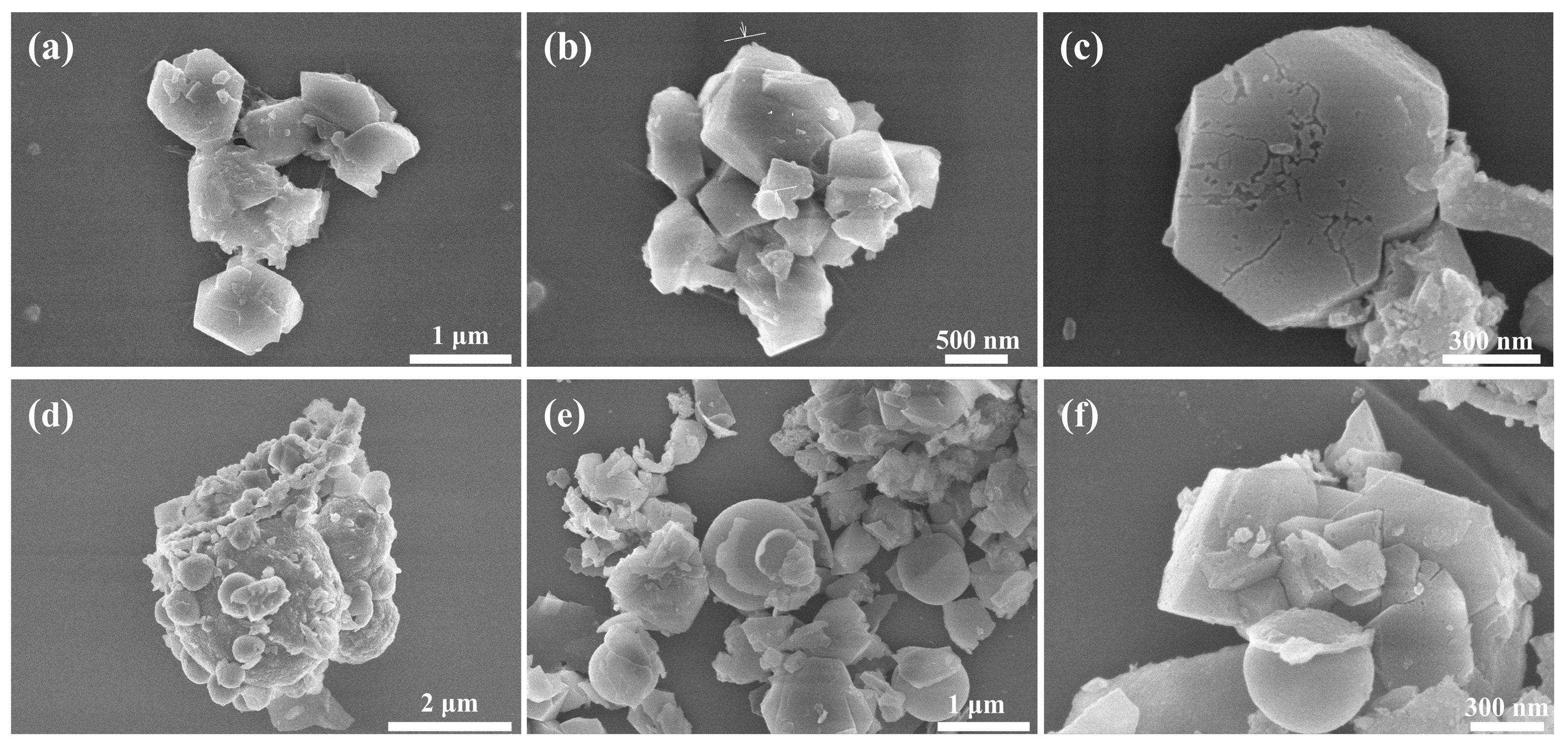
3.1. Structural Analysis of Al-12Si@Al2O3 Microcapsules

As shown in Figure 1a, the selected Al-Si alloy has a standard spherical structure and a relatively smooth surface, and the particle size is evenly distributed at 4–8 μm. After calcination at 800 °C under an air atmosphere, the unencapsulated alloy microspheres melted and underwent a solid–liquid phase transition (Figure 1b). The thermally oxidized Al2O3 thin film formed on the surface at the early stage of heating was too weak to maintain the original morphology, leading to leakage of the liquid PCM inside and significant structural collapse. In addition, these leaked alloys were rapidly oxidized to Al2O3 by air, resulting in a significant reduction in the overall latent heat value of the material. These results indicate that the original alloy PCM does not have sufficient thermal stability and needs to be further microencapsulated.
Microencapsulation of the alloy PCM was achieved with steam-assisted oxidation treatment [31,32]. Figure 2 shows the XRD spectra of the pristine Al-12wt%Si alloy and the microcapsule samples before and after calcination; it can be found that for the two encapsulated samples, in addition to all the absorption peaks in the pure alloy, two additional sharp diffraction peaks of Al2O3/Al(OH)3 are also clearly observed [27,33]. The Al(OH)3 that appears after steam treatment can be transformed into the corresponding Al2O3 after calcination. Due to the low Si content and the presence of Al2O3 film on the surface, the Al diffraction peaks are sharp, and the intensity of the Si absorption peaks is very low. The diffraction peak intensities of Al and Si are slightly increased after sintering treatment, which may be due to a small amount of leakage of molten Al-Si alloy at the weak position of the composite. Moreover, the leaking alloy can be rapidly oxidized to an extra silica-containing Al2O3 shell in a high-temperature oxygen-containing environment, spontaneously completing the defect repair.
Figure 3 shows the SEM images of the alloy microcapsule before and after calcination treatment. As shown in Figure 3a,b, the surface of the uncalcined microsphere is covered with a relatively dense Al(OH)3 layer, which mainly consists of fine rod-like long crystals and a few columnar crystals. After being calcined at 800 °C, the sample can still maintain a basic spherical morphology, with no obvious melting marks or cracks caused by alloy leakage (Figure 3c,d), and the stability of the sample is significantly improved. After calcination, the surface morphology of the microsphere changes from smooth to a rough bulging structure, which may be attributed to the thermal expansion caused by the solid–liquid transition of the alloy during the calcination heating process. Most of the original fine rod-like bayerite crystals decomposed and reorganized to form a continuous matrix layer with improved densification.

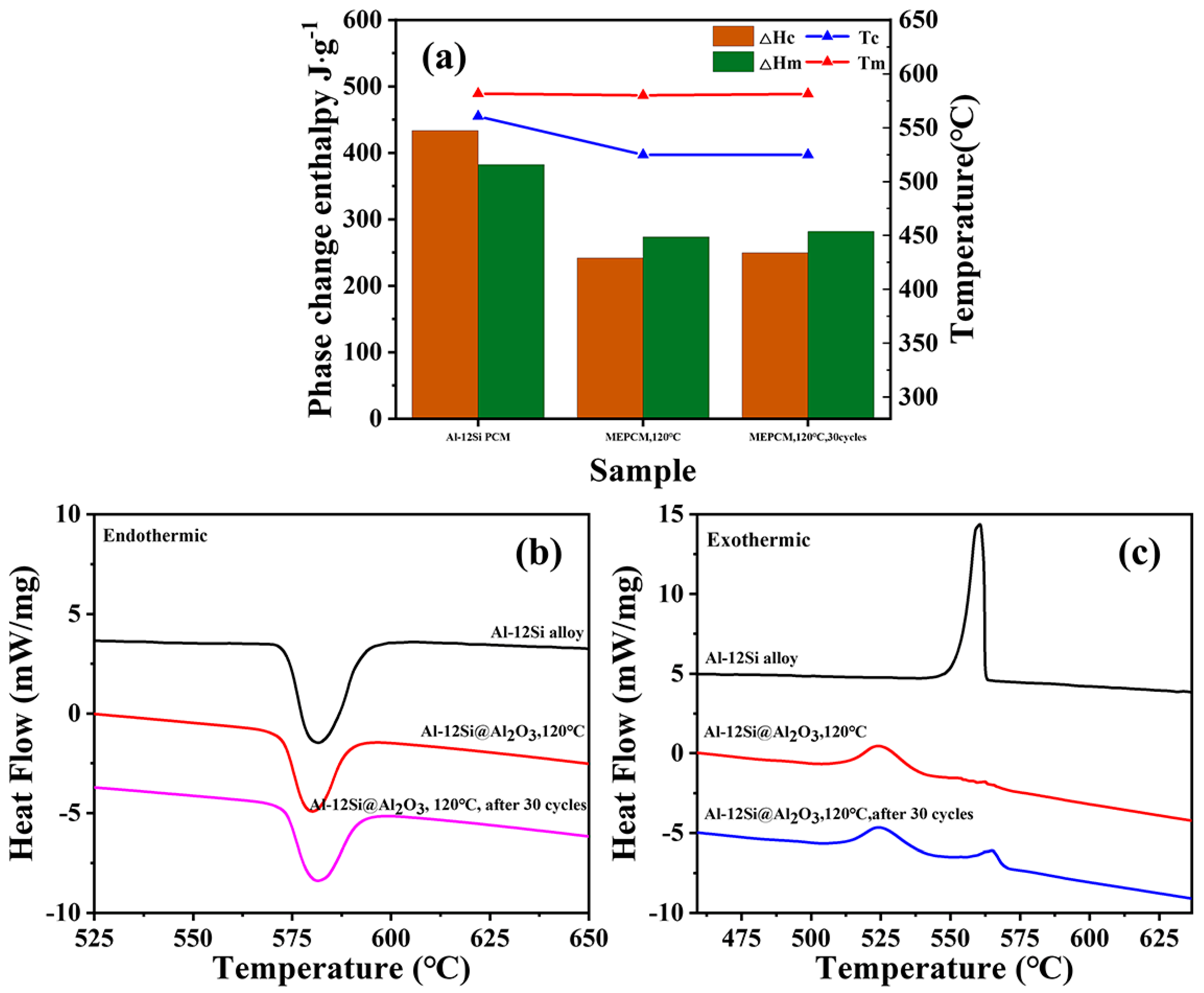
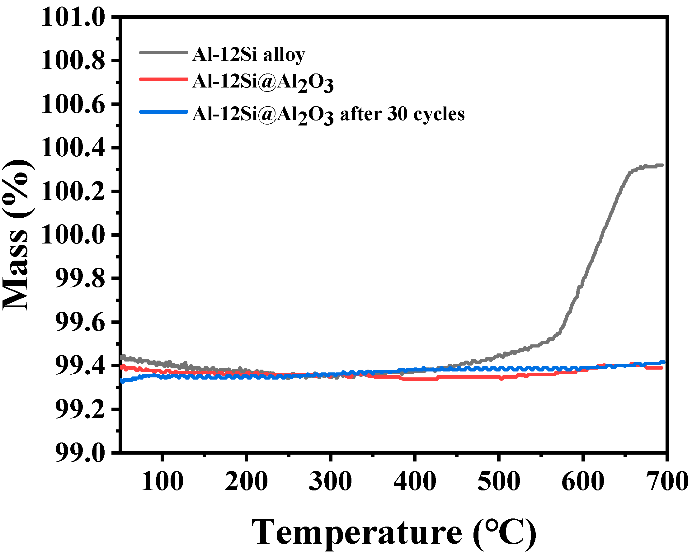
3.2. Thermal Properties and Stability of Al-12Si@Al2O3 Microcapsules

The thermal properties of the microencapsulated sample before and after cycling were characterized by TG-DSC, and the following classical equations were used to calculate the encapsulation rate (Een), energy storage efficiency (Ees), and thermal storage capacity (Ces) of the microcapsules, respectively. The specific results are shown in Figure 4 and Table 1. Among them, H m , p c m and H c , p c m are the crystallization enthalpy and melting enthalpy of the alloy PCM, respectively, while H m , s a m p l e and H c , s a m p l e are the crystallization enthalpy and melting enthalpy of the microcapsule sample, respectively.
  E e n = H m , s a m p l e H m , p c m × 100 %
E e s = H m , s a m p l e + H c , s a m p l e H m , p c m + H c , p c m × 100 %
  C e s = H m , s a m p l e + H c , s a m p l e H m , p c m H m , p c m + H c , p c m H m , s a m p l e × 100 % = E e s E e n × 100 %
Only one melting endothermic peak could be found during the heating process of the sample before and after encapsulation, and the melting peak position was about 581 °C. During the cooling crystallization process (Figure 4c), the pure alloy possessed a sharp exothermic peak at 560.57 °C, while the exothermic peak of the encapsulated sample became broad and flat. After performing encapsulation, the exothermic temperature range of the sample was significantly increased from about 20 °C to 65 °C, and the crystallization temperature (Tc) was significantly lower than the original alloy by more than 33 °C, at about 524.87 °C. Similarly, the degree of subcooling required to complete the solid–liquid phase-change process in the microencapsulated samples increased by 33.99 °C from 21.15 °C prior to encapsulation. The above data indicate that the presence of an Al2O3 shell significantly affects the crystallization behavior of the alloy PCM, which may be attributed to a decrease in the thermal conductivity of the inorganic shell layer outside the microcapsule, as well as phase transition temperature hysteresis caused by the internal space confinement effect. Before encapsulation, the molten Al-Si alloy relies on the nucleation point for rapid heterogeneous nucleation at low supercooling. After encapsulation, the phase-change components are encapsulated in their own separate small spaces, and can only be driven by greater supercooling to complete homogeneous nucleation due to the lack of nucleation points.
As shown in Table 1, the microcapsule sample has a high heat storage enthalpy of about 283.73 J/g. Since the inorganic shell does not participate in the phase-change process, the calculated coating rate is about 74.20%, and the heat storage capacity is about 88.42%, which indicates the excellent heat storage performance of the sample. In order to characterize the recycling performance of the prepared Al-12Si@Al2O3, thirty phase transition cycles (the test temperature range was 500–600 °C) were tested in an air atmosphere. It can be seen from Figure 4b,c that the melting–solidification DSC curves for the sample before and after the phase-change cycle were basically the same; meanwhile, phase-change enthalpy and the degree of supercooling also did not change significantly, indicating that the encapsulated Al-12Si@Al2O3 sample had favorable cycle thermal stability. Furthermore, after 30 cycles, the Tc value and melting enthalpy of the sample remained essentially unchanged. Especially for the enthalpy of melting, nearly 99% was retained compared with uncirculated Al-12Si@Al2O3 (about 280.34 J/g). It was calculated that the coating parameters remained at an initial high level, and the internal PCM core could still effectively absorb and release latent heat after undergoing multiple cycles of phase change, proving that the microcapsule sample had good phase-change stability. In summary, well-encapsulated high-temperature phase-change microcapsules with high heat storage capacity and excellent thermal stability can be obtained with the vapor treatment process.
As can be seen from Figure 5a–d, the surface morphology of Al-12Si@Al2O3 before and after cycling does not change significantly, the Al2O3 shell layer basically remains intact, and there is no obvious leakage of the alloy PCM or crushing of the shell layer, which indicates that the prepared microcapsule has good thermal stability in phase-change cycling. The surface microstructure of the microencapsulated sample after cycling was observed using TEM (Figure 5e,f), and it was found that the spherical microcapsule remained a complete morphology. The dark edge of the sample observed in Figure 5e proves the presence of the Al2O3 shell. As there is a certain gap between the shell layer and the inner core material, this will effectively avoid shell rupture due to volume expansion of the Al-Si alloy core during cyclic solid–liquid phase-change transformations. Overall, the Al2O3 thin shell not only prevented the leakage of liquid PCM but also ensured the high heat storage enthalpy and good encapsulation rate of the material as a whole.
In addition, the thermogravimetric curves of the original Al-Si alloy, as well as the microcapsule samples before and after cycling, were comparatively studied to characterize their thermal stability (during the test, the samples were heated from room temperature to 700 °C at a heating rate of 10 °C/min and kept at a constant temperature for 10 min), and the results are shown in Figure 6. The mass of the unencapsulated PCM increases significantly with an increase in temperature, whereas the overall mass of the encapsulated microcapsule changes insignificantly and the thermal stability increases greatly. The TGA curve for the pristine alloy can be divided into three stages: (1) from room temperature to 250 °C, adsorbed water present on the surface of the alloy microspheres is desorbed during the heating process, and the mass decreases slightly by about 0.06%; (2) around 330–570 °C, O2 leads to the slow oxidation of partial Al on the alloy surface to form Al2O3, with a slow weight gain of about 0.19% of the sample mass; (3) around 570–700 °C, rapid weight gain for the sample is about 0.82%, which is attributed to the solid–liquid phase transition of the alloy’s composition at a temperature close to the melting point. The contact surface area between the liquid PCM and O2 increases significantly, so the Al phase can be rapidly oxidized to Al2O3 film. For the Al-12Si@Al2O3 microcapsule sample, the thermogravimetric curve is mainly divided into two stages: (1) below 250 °C, its mass also slightly decreases owing to the removal of water; (2) from 250 °C to 700 °C, there is no obvious mass change in the sample. Comparing the changes in the quality of the samples before and after encapsulation, it can be confirmed that this kind of shell-layer microencapsulation process can effectively prevent leakage and oxidation of the internal alloy during the PCM phase transition process, improving thermal stability. The thermogravimetric curve of the Al-12Si@Al2O3 microcapsules after 30 complete phase-transition cycles also proves that the sample has good thermal cycling stability, as the mass does not change significantly (the curve basically maintains the level). The above tests show that the synthesized alloy phase-change microcapsule has both high latent heat and good thermal stability (800 °C), which can provide a solid basis for the construction of heat storage/catalysis multifunctional composite FCC catalysts (hydrothermal aging at 800 °C for 17 h) in the next step.

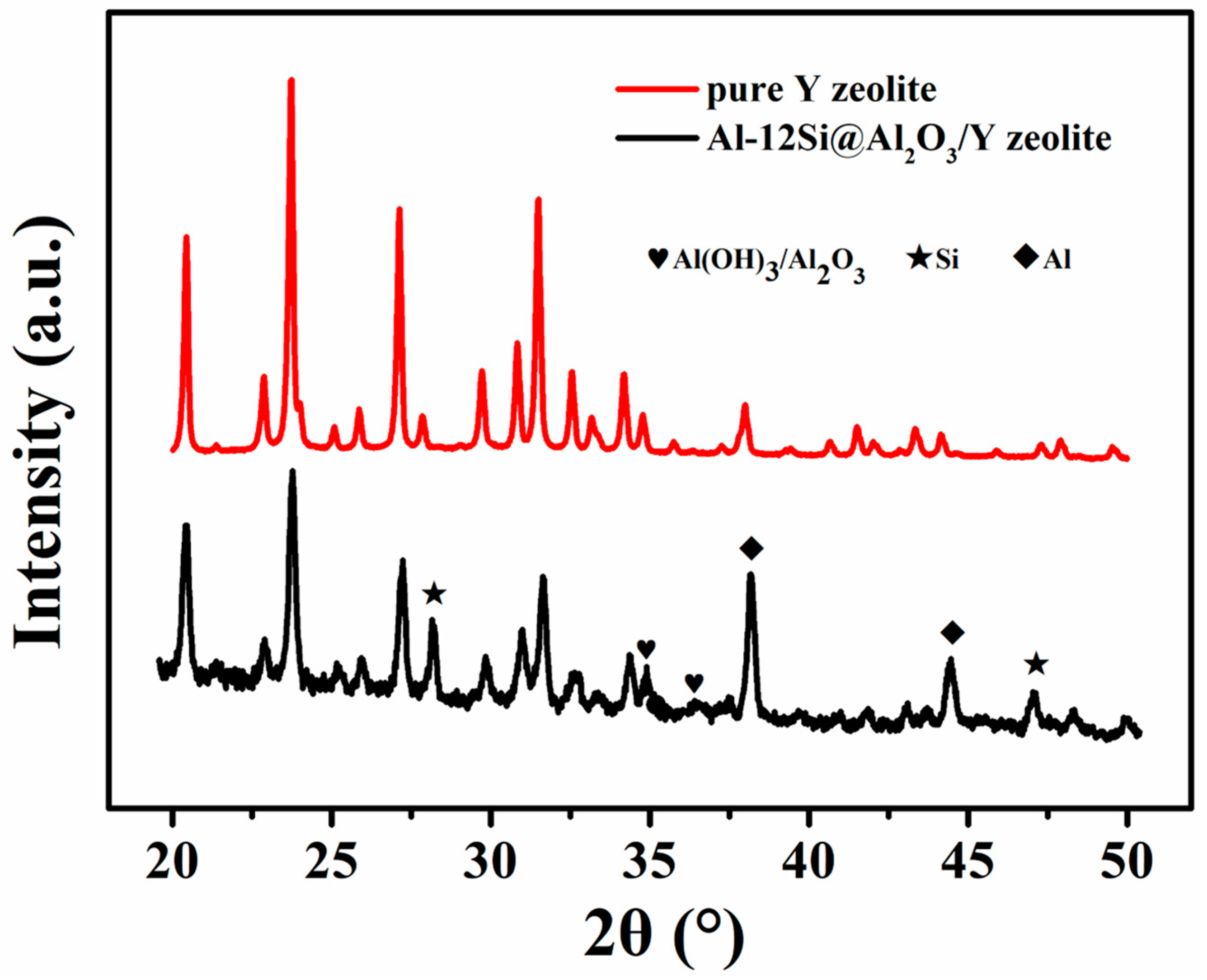
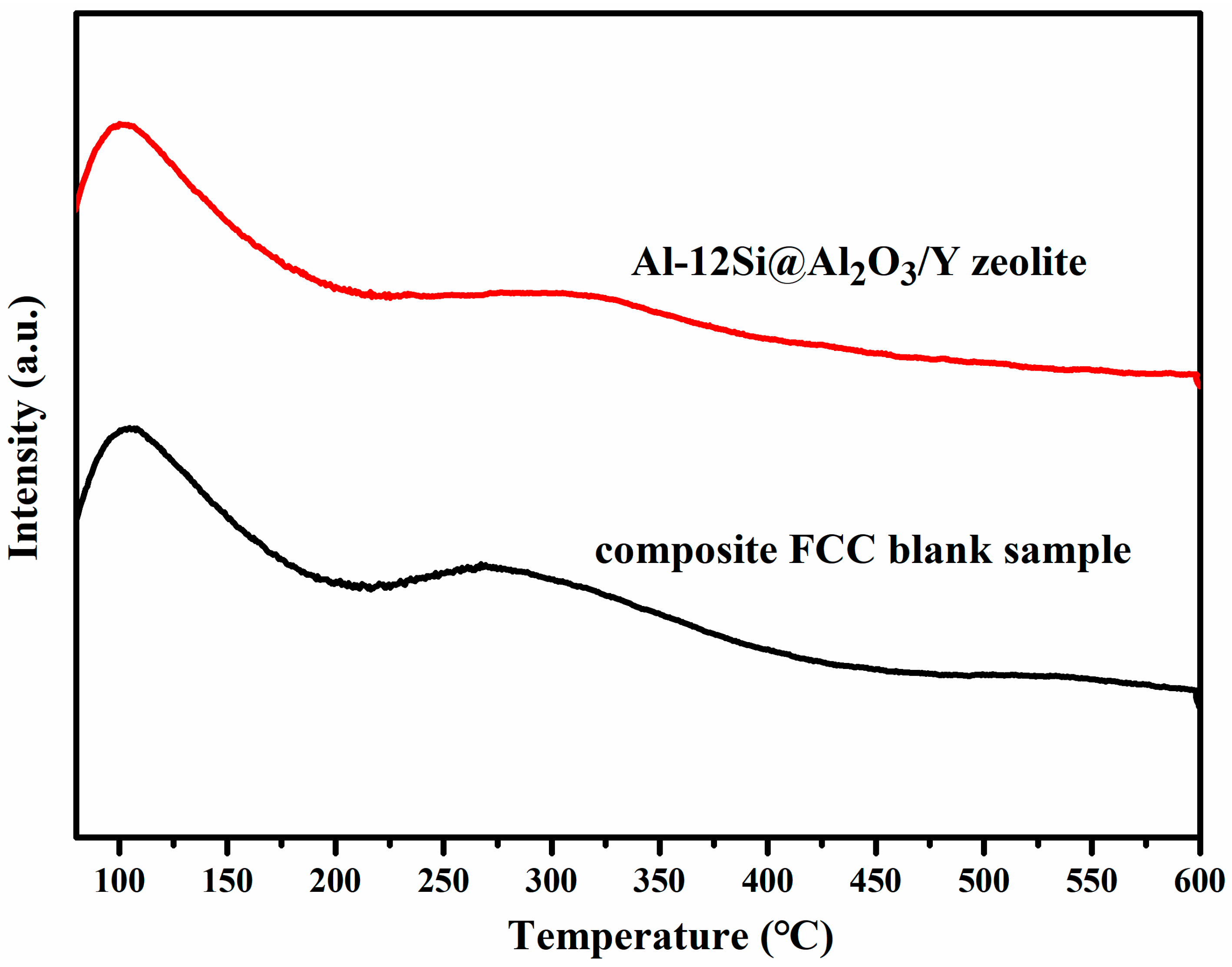
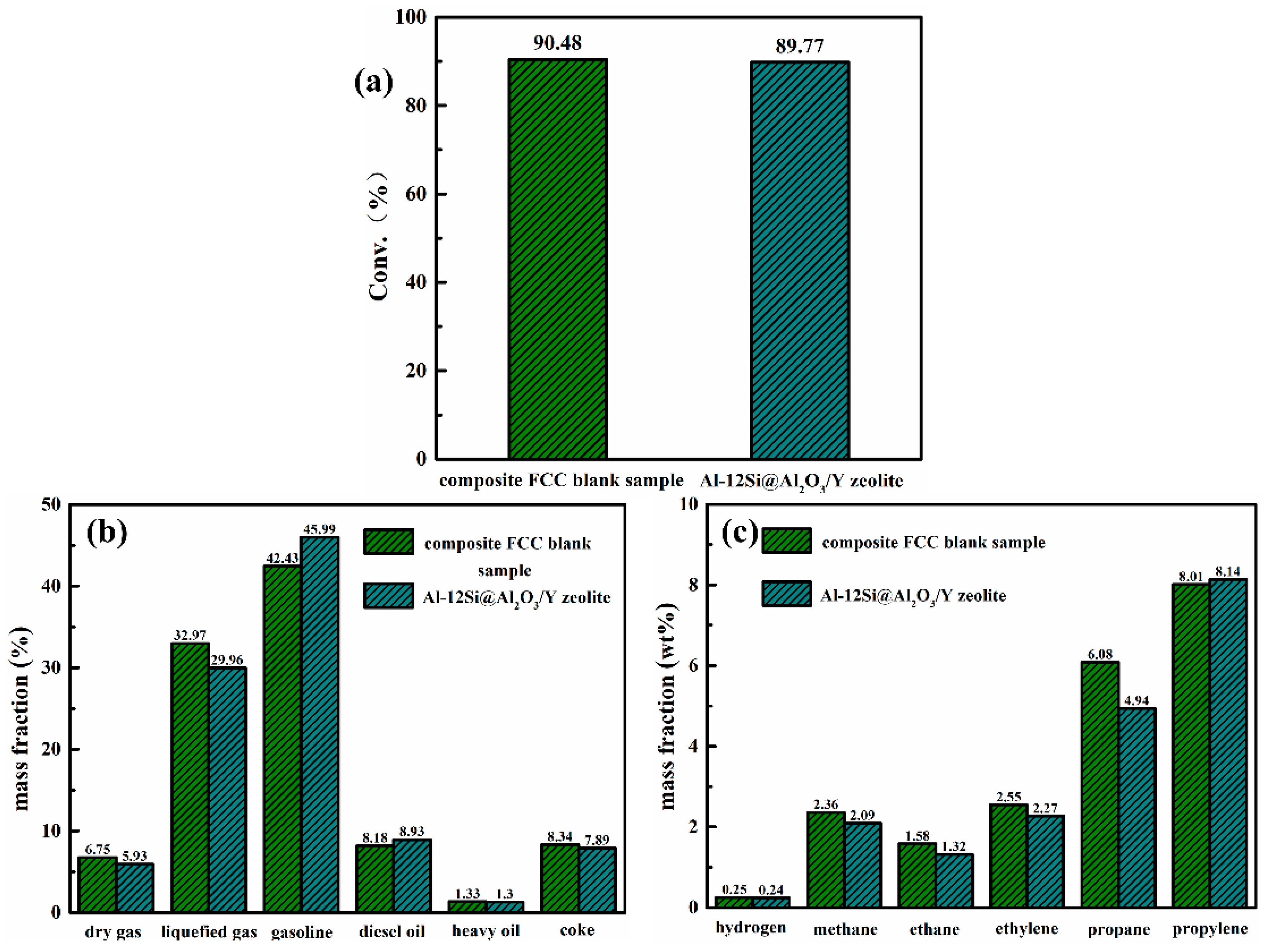
3.3. Structure and Performance Analysis for Al-12Si@Al2O3/Y Zeolite

Figure 7 displays the XRD patterns for the pure Y zeolite and Al-12Si@Al2O3/Y zeolite, and the phase structure of the Y zeolite is completely consistent with that reported in the literature [34,35]. This may be due to the larger mass ratio and stronger diffraction intensity of the catalytic component, resulting in the composite sample showing only the diffraction peaks of the Y zeolite. However, by carefully comparing the XRD results of the two samples, it is not difficult to find that the diffraction peaks belonging to the PCM microcapsule should just be covered rather than absent, because the relative intensity of the peaks at the positions of these peaks is obviously higher than that of the pure Y zeolite, demonstrating that the PCM component has good thermal stability and successfully completes assembly with the catalytic component.
The micro-morphology of the two prepared FCC catalysts (Al-12Si@Al2O3/Y zeolite and its blank sample) was characterized by SEM after grinding treatment, and the results are shown in Figure 8. An amorphous structural material and regular Y zeolite can be clearly observed in the FCC blank samples (Figure 8a–c), and the former is mainly derived from the silica–aluminum sol binder used for granulation. The contained Y zeolite particles possess a regular FAU octahedral structure, with particle sizes between 500 nm and 1.5 μm. After hydrothermal aging at 800 °C (Figure 8d–f), partial Y zeolites start showing a continuous mesoporous pore structure (about 10–20 nm), which may be due to the removal of high-temperature water vapor on the aluminum of the zeolite skeleton. For the Al-12Si@Al2O3/Y zeolite, an obvious composite structure of spherical microcapsules connected by a binder with a Y molecular sieve can be observed. The phase-change microcapsules can still maintain their complete spherical morphology, indicating their good thermal stability. This will facilitate the rapid transfer of heat from the catalyst surface during the FCC process and promote the realization of local in situ thermal management and energy recycling.
The N2 adsorption–desorption isotherms and pore size distributions of the Al-12Si@Al2O3/Y zeolite and its blank sample are shown in Figure 9, and the detailed texture performance parameters are listed in Table 2. In Figure 9a, both samples display a typical type-IV adsorption isotherm equipped with a type-H3 hysteresis loop according to the IUPAC classification [36,37]. This indicates the presence of a mesoporous structure, especially the slit pores generated by the accumulation of microcapsule components and Y zeolite components. The pore size distribution image (Figure 9b) intuitively confirms that the two materials have similar hierarchical pore structures. In addition to micropores of less than 2 nm, mesopores are mainly distributed in the ranges of 2–4 nm and 8–32 nm. Comparing the data in Table 2, the values of SBET, SMic, VMic, VT, and VMes for both samples are virtually identical. Further verifying the acidity features of the target sample and the composite FCC blank sample, NH3-TPD tests were performed to determine the strength and number of acidic sites. In general, the desorption peaks located at the low-temperature zone (100–250 °C), medium-temperature zone (250–400 °C), and high-temperature zone (400–600 °C) are ascribable to weak acid sites, medium acid sites, and strong acid sites, respectively [38,39]. It can be seen in Figure 10 that all the curves possess only two desorption peaks: a strong peak in the low-temperature zone and a relatively weak peak in the medium-temperature zone, showing the absence of strong acid sites and that the majority of acidity in all samples is mainly induced by weak acid sites. The concentrations of acid sites with different strengths were further quantified with the NH3-TPD curves of the two samples (Table 3). It can be seen that the Al-12Si@Al2O3/Y zeolite and the composite blank sample remain essentially the same in terms of the number of each type of acid site, just like the texture performance parameters. These results explain the rationality of the blank sample setting.
ICP tests were used to analyze the elements of the two prepared samples. The contents of Al and Si elements in the Al-12Si@Al2O3/Y zeolite sample were 20.34 wt% and 23.84 wt%, respectively. For the composite FCC blank sample, the contents of both elements were slightly lower, 18.77 wt% and 22.51 wt%, respectively, owing to the absence of the Si element and relatively small mass ratio of the Al element in the pure Al2O3 phase compounded with the zeolite catalytic component of the blank sample. The catalytic performance and product distribution of the composite FCC blank samples and functional composite FCC catalysts were characterized using light diesel oil as a feedstock oil. As shown in Figure 11a, the total substrate conversions for the blank and target sample were basically the same (90.48% and 89.77%), indicating that the addition of the PCM temperature-controlled component did not have a direct promoting effect on the catalytic process. In addition, the extremely low catalyst-to-oil ratio of the Al-12Si@Al2O3/Y zeolite FCC system (close to 1.70) also makes its conversion of about 90% show obvious competitiveness compared with other reported catalytic systems (Table 4), even if the reaction conditions of all FCC systems are basically inconsistent. With further comparative analysis of the product distribution diagram (Figure 11b), obvious differences between the two catalytic systems can be found. For the functional composite FCC catalyst, the proportions of light oil products, including diesel oil and gasoline, were 45.99% and 8.93%, respectively, which are significantly higher than those of the blank sample (42.43% and 8.18%). At the same time, the proportions of both heavy oil and coke products presented a decreasing trend, especially for coke, decreasing from 8.38% to 7.89%, directly proving that the presence of a PCM temperature-controlled zone positively affects the product distribution. Since the conversions of the above two reaction systems are basically the same, it can be calculated that the actual yield of coke products in the functional composite catalyst system is significantly lower than that of the blank sample. In general, coke is formed as a result of occurring side reactions, such as incomplete dissociation of long-chain alkanes, olefin repolymerization, and alkane rearrangement [40,41], and a large amount of coke will easily lead to a carbon deposition phenomenon, blocking or even destroying the active sites on the surface, thus affecting the activity and stability of the catalyst. Therefore, for the functional composite FCC catalyst, the reasons for effective optimization of the product distribution may be as follows: due to the endothermic effect of the FCC process, the blank sample will have a localized low-temperature phenomenon, which easily induces more side reactions, and eventually leads to a reduction in the selectivity of the main product and the generation of more coke. After assembling Al-12Si@Al2O3, the microcapsule component can spontaneously release latent heat when the local temperature decreases (the reaction temperature is near the phase transition point of the alloy PCM), which can promote the positive movement of the chemical equilibrium of the FCC main reaction while regulating the reaction temperature, as well as attenuating the tendency for the occurrence of side reactions, thus optimizing the product distribution. Interestingly, further comparison of the partial cracked gas products of each catalytic system shows that the functional composite FCC catalytic system is less inclined to the generation of other small molecule products, except propylene (Figure 11c).
Recycling experiments on FCC were performed with the prepared Al-12Si@Al2O3/Y zeolite composite FCC catalyst to evaluate its reusability. During the whole cycle, the sample did not undergo any treatment at the end of the previous round of catalysis, and proceeded directly to the next round of catalysis. After three complete catalytic cycles, total substrate conversion and coke yield both varied, but not significantly (substrate conversion decreased from 89.77% to 80.67% and coke yield increased from 7.89 wt% to 9.41 wt%), showing favorable recyclability for the composite catalyst. Figure 12a,b presents the corresponding SEM pattern and XRD curve for the reused Al-12Si@Al2O3/Y zeolite after four cycles. The basic morphology and crystal structure all show no obvious change compared with the pristine catalyst, further proving its good stability. Overall, such PCM@Catalyst composites should have remarkable prospects for development in the FCC process.

4. Conclusions

In this paper, Al-12wt%Si alloy microspheres were used as phase-change components, and Al-12Si@Al2O3 microcapsule samples with good heat storage capacity and phase-change-cycle stability were synthesized by combining the steam-assisted oxidation route and the high-temperature calcination process. The corresponding heat storage/catalysis multifunctional composite FCC catalyst was further constructed by hydrothermal aging. The Al2O3 shell formed in situ can not only effectively solve the leakage of the internal PCM core material in a high-temperature environment but also ensure that most of the latent heat of the original PCM component is stably retained and has good thermal-cycle stability, providing a prerequisite for the subsequent construction of a PCM@Catalyst composite. After combining the synthesized microcapsule with the FCC catalytic component Y zeolite, it was determined from the FCC catalytic experiments that the introduction of the PCM component can effectively improve product distribution. Additionally, its own latent heat release effect is conducive to the effective promotion of the FCC main reaction, improving the selectivity of the target products and reducing the generation of coke. The results prove that the synthesized Al-12wt%Si@Al2O3/Y zeolite may have great application potential in the practical field of FCC.

Author Contributions

Conceptualization, G.A.; Methodology, Z.C.; Software, S.L.; Investigation, G.A.; Resources, Y.O.; Writing—original draft, G.A. and Z.C.; Writing—review & editing, H.G.; Project administration, H.G. All authors have read and agreed to the published version of the manuscript.

Funding

This work was supported by the SINOPEC Research Institute of Petroleum Processing, Natural Science Foundation of the Guangdong Province of China (2022A1515011918), and Fundamental Research Funds for the Central Universities (FRF-IDRY-20-004).

Data Availability Statement

Data sharing not applicable.

Conflicts of Interest

There are no conflicts of interest to declare.

References

  1. Dupain, X.; Makkee, M.; Moulijn, J.A. Optimal conditions in fluid catalytic cracking: A mechanistic approach. Appl. Catal. A Gen. 2006, 297, 198–219. [Google Scholar] [CrossRef]
  2. Huang, Z.; Ho, T.C. Effect of thermolysis on resid droplet vaporization in fluid catalytic cracking. Chem. Eng. J. 2003, 91, 45–58. [Google Scholar] [CrossRef]
  3. Hosseini, S.M.; Safaei, M.R.; Estelle, P.; Jafarnia, S.H. Heat transfer of water-based carbon nanotube nanofluids in the shell and tube cooling heat exchangers of the gasoline product of the residue fluid catalytic cracking unit. J. Therm. Anal. Calorim. 2020, 140, 351–362. [Google Scholar] [CrossRef]
  4. Stratiev, D.; Ivanov, M.; Chavdarov, I.; Argirov, G.; Strovegli, G. Revamping fluid catalytic cracking unit, and optimizing catalyst to process heavier feeds. Appl. Sci. 2023, 13, 2017. [Google Scholar] [CrossRef]
  5. Stratiev, D.; Shishkova, I.; Ivanov, M.; Dinkov, R.; Georgiev, B.; Argirov, G.; Atanassova, V.; Vassilev, P.; Atanassov, K.; Yordanov, D.; et al. Role of catalyst in optimizing fluid catalytic cracking performance during cracking of H-oil-derived gas oils. Acs Omega 2021, 6, 7626–7637. [Google Scholar] [CrossRef]
  6. Nazarova, G.Y.; Ivashkina, E.N.; Ivanchina, E.D.; Mezhova, M.Y. A model of catalytic cracking: Catalyst deactivation induced by feedstock and process variables. Catalysts 2022, 12, 98. [Google Scholar] [CrossRef]
  7. Farshi, A.; Abri, H.R. The addition of ZSM-5 to a fluid catalytic cracking catalyst for increasing olefins in fluid catalytic cracking light gas. Petrol. Sci. Technol. 2012, 30, 1285–1295. [Google Scholar] [CrossRef]
  8. Trujillo, W.R.; De Wilde, J. Computational fluid dynamics simulation of fluid catalytic cracking in a rotating fluidized bed in a static geometry. Ind. Eng. Chem. Res. 2010, 49, 5288–5298. [Google Scholar] [CrossRef]
  9. Stratiev, D.; Shishkova, I.; Ivanov, M.; Chavdarov, I.; Yordanov, D. Dependence of fluid catalytic cracking unit performance on H-oil severity, catalyst activity, and coke selectivity. Chem. Eng. Technol. 2020, 43, 2266–2276. [Google Scholar] [CrossRef]
  10. Hiramatsu, Y.; Aita, Y.; Umeki, T. Effect of acid properties of catalysts on fluid catalytic cracking of residual oil. J. Jpn. Petrol. Inst. 2012, 55, 319–325. [Google Scholar] [CrossRef]
  11. Alabdullah, M.A.; Shoinkhorova, T.; Dikhtiarenko, A.; Ould-Chikh, S.; Rodriguez-Gomez, A.; Chung, S.H.; Alahmadi, A.O.; Hita, I.; Pairis, S.; Hazemann, J.L.; et al. Understanding catalyst deactivation during the direct cracking of crude oil. Catal. Sci. Technol. 2022, 12, 5657–5670. [Google Scholar] [CrossRef]
  12. Liu, L.M. A SoC Controller for Energy Saving and Environmental Protection. Mater. Sci. Environ. Prot. Appl. Res. 2014, 908, 477–480. [Google Scholar] [CrossRef]
  13. Wei, Q.F.; Guo, A.N.; Wei, L.X.; Ni, W.Y. Analysis of the mechanism of renewable energy on energy-saving and environmental protection industry: Empirical evidence from four countries. Energy Rep. 2022, 8, 205–217. [Google Scholar] [CrossRef]
  14. Zivkovic, S.; Todorovic, M.; Pejcic, D. Improvements in environmental protection through optimization of production processes a case study. Fresen. Environ. Bull. 2016, 25, 2725–2735. [Google Scholar]
  15. de Gracia, A.; Cabeza, L.F. Phase change materials and thermal energy storage for buildings. Energy Build. 2015, 103, 414–419. [Google Scholar] [CrossRef]
  16. Kibria, M.A.; Anisur, M.R.; Mahfuz, M.H.; Saidur, R.; Metselaar, I.H.S.C. A review on thermophysical properties of nanoparticle dispersed phase change materials. Energy Convers. Manag. 2015, 95, 69–89. [Google Scholar] [CrossRef]
  17. Pielichowska, K.; Pielichowski, K. Phase change materials for thermal energy storage. Prog. Mater. Sci. 2014, 65, 67–123. [Google Scholar] [CrossRef]
  18. Shi, J.M.; Qin, M.L.; Aftab, W.; Zou, R.Q. Flexible phase change materials for thermal energy storage. Energy Storage Mater. 2021, 41, 321–342. [Google Scholar] [CrossRef]
  19. Qiu, L.; Ouyang, Y.X.; Feng, Y.H.; Zhang, X.X. Review on micro/nano phase change materials for solar thermal applications. Renew. Energy 2019, 140, 513–538. [Google Scholar] [CrossRef]
  20. Su, W.G.; Darkwa, J.; Kokogiannakis, G. Review of solid-liquid phase change materials and their encapsulation technologies. Renew. Sustain. Energy Rev. 2015, 48, 373–391. [Google Scholar] [CrossRef]
  21. Fukahori, R.; Nomura, T.; Zhu, C.; Sheng, N.; Okinaka, N.; Akiyama, T. Thermal analysis of Al-Si alloys as high-temperature phase-change material and their corrosion properties with ceramic materials. Appl. Energy 2016, 163, 1–8. [Google Scholar] [CrossRef]
  22. Kageyama, Y.; Morita, K. Compositional and thermophysical study of Al-Si- and Zn-Al-Mg-based eutectic alloys for latent heat storage. High Temp. Mat. Pract.-ISR 2023, 42, 20220269. [Google Scholar] [CrossRef]
  23. Ma, F.; Zhang, P. Investigation on the performance of a high-temperature packed bed latent heat thermal energy storage system using Al-Si alloy. Energy Convers. Manag. 2017, 150, 500–514. [Google Scholar] [CrossRef]
  24. Wang, Z.Y.; Wang, H.; Yang, M.; Sun, W.W.; Yin, G.F.; Zhang, Q.Y.; Ren, Z.F. Thermal reliability of Al-Si eutectic alloy for thermal energy storage. Mater. Res. Bull. 2017, 95, 300–306. [Google Scholar] [CrossRef]
  25. He, F.; Chao, S.; He, X.D.; Li, M.W. Inorganic microencapsulated core/shell structure of Al-Si alloy micro-particles with silane coupling agent. Ceram. Int. 2014, 40, 6865–6874. [Google Scholar] [CrossRef]
  26. Nomura, T.; Yoolerd, J.; Sheng, N.; Sakai, H.; Hasegawa, Y.; Haga, M.; Saito, G.; Akiyama, T. Microencapsulation of eutectic and hyper-eutectic Al-Si alloy as phase change materials for high-temperature thermal energy storage. Sol. Energy Mat. Sol. C 2018, 187, 255–262. [Google Scholar] [CrossRef]
  27. Nomura, T.; Zhu, C.; Sheng, N.; Saito, G.; Akiyama, T. Microencapsulation of metal-based phase change material for high-temperature thermal energy storage. Sci. Rep. 2015, 5, 9117. [Google Scholar] [CrossRef] [PubMed]
  28. Wang, C.P.; Huang, Y.; Wei, H.T.; Yu, F.Z.; Wang, M.S.; Guo, Y.H.; Zhang, J.B.; Deng, R.; Yang, S.Y.; Liu, X.J. A brief strategy for designing self-encapsulated Al-Si base phase change materials with high thermal energy storage performance. J. Energy Storage 2023, 62, 106957. [Google Scholar] [CrossRef]
  29. Zhu, S.L.; Nguyen, M.T.; Yonezawa, T. Micro- and nano-encapsulated metal and alloy-based phase-change materials for thermal energy storage. Nanoscale Adv. 2021, 3, 4626–4645. [Google Scholar] [CrossRef] [PubMed]
  30. Zou, Q.C.; Zhang, Z.X.; Dong, Z.H.; Zhang, J.J.; Dong, B.W.; Fu, H.T.; An, X.Z. Electromagnetic self-encapsulation of carbon fiber reinforced Al matrix composite phase change material for high-temperature thermal energy storage. J. Alloys Compd. 2022, 901, 163560. [Google Scholar] [CrossRef]
  31. Han, C.J.; Gu, H.Z.; Zhang, M.J.; Huang, A.; Zhang, Y.; Wang, Y. Al-Si@Al2O3@mullite microcapsules for thermal energy storage: Preparation and thermal properties. Sol. Energy Mat. Sol. C 2020, 217, 110697. [Google Scholar] [CrossRef]
  32. Han, C.J.; Gu, H.Z.; Zhang, M.J.; Huang, A.; Zhang, Y.; Wang, Y. Thermal properties of Al-Si/Al2O3 core-shell particles prepared by using steam hydration method. J. Alloys Compd. 2020, 817, 152801. [Google Scholar] [CrossRef]
  33. Nomura, T.; Sheng, N.; Zhu, C.; Saito, G.; Hanzaki, D.; Hiraki, T.; Akiyama, T. Microencapsulated phase change materials with high heat capacity and high cyclic durability for high-temperature thermal energy storage and transportation. Appl. Energy 2017, 188, 9–18. [Google Scholar] [CrossRef]
  34. Katoh, M.; Kimura, M.; Sugino, M.; Horikawa, T.; Nakagawa, K.; Sugiyama, S. Modification of commercial NaY zeolite to give high water diffusivity and adsorb a large amount of water. J. Colloid Interf. Sci. 2015, 455, 220–225. [Google Scholar] [CrossRef] [PubMed]
  35. Katsuki, H.; Furuta, S.; Komarneni, S. Microwave versus conventional-hydrothermal synthesis of NaY zeolite. J. Porous Mat. 2001, 8, 5–12. [Google Scholar] [CrossRef]
  36. Hasanudin, H.; Asri, W.R.; Fanani, Z.; Adisti, S.J.; Hadiah, F.; Maryana, R.; Al Muttaqii, M.; Zhu, Z.Y.; Machado, N.T. Facile fabrication of SiO2/Zr assisted with EDTA complexed-impregnation and templated methods for crude palm oil to biofuels conversion via catalytic hydrocracking. Catalysts 2022, 12, 1522. [Google Scholar] [CrossRef]
  37. Seo, S.; Chaikittisilp, W.; Koike, N.; Yokoi, T.; Okubo, T. Porous inorganic-organic hybrid polymers derived from cyclic siloxane building blocks: Effects of substituting groups on mesoporous structures. Micropor. Mesopor. Mat. 2019, 278, 212–218. [Google Scholar] [CrossRef]
  38. Deng, C.S.; Zhang, J.J.; Dong, L.H.; Huang, M.N.; Bin, L.; Jin, G.Z.; Gao, J.B.; Zhang, F.Y.; Fan, M.G.; Zhang, L.M.; et al. The effect of positioning cations on acidity and stability of the framework structure of Y zeolite. Sci. Rep. 2016, 6, 23382. [Google Scholar] [CrossRef]
  39. An, G.Q.; Gao, H.Y.; Luo, Y.B.; Ouyang, Y.; Wang, G.; Liu, S.Q.; Wang, C.A.; Liu, Z.Y.; Cheng, Z.X.; Shu, X.T. Optimization of MOFs-induced strategy for preparing anatase-free hierarchical TS-1 towards 1-hexene epoxidation: TPAOH dosage regulation, silanization and stabilizing acidic sites. Micropor. Mesopor. Mat. 2023, 360, 112704. [Google Scholar] [CrossRef]
  40. Shi, J.J.; Guan, J.Y.; Guo, D.W.; Zhang, J.S.; France, L.J.; Wang, L.F.; Li, X.H. Nitrogen chemistry and coke transformation of FCC coked catalyst during the regeneration process. Sci. Rep. 2016, 6, 27309. [Google Scholar] [CrossRef]
  41. Cumming, K.A.; Wojciechowski, B.W. Hydrogen transfer, coke formation, and catalyst decay and their role in the chain mechanism of catalytic cracking. Catal. Rev. 1996, 38, 101–157. [Google Scholar] [CrossRef]
  42. Zhao, J.; Yin, Y.C.; Li, Y.; Chen, W.Y.; Liu, B.J. Synthesis and characterization of mesoporous zeolite Y by using block copolymers as templates. Chem. Eng. J. 2016, 284, 405–411. [Google Scholar] [CrossRef]
  43. Zhao, J.; Wang, G.G.; Qin, L.H.; Li, H.Y.; Chen, Y.; Liu, B.J. Synthesis and catalytic cracking performance of mesoporous zeolite Y. Catal. Commun. 2016, 73, 98–102. [Google Scholar] [CrossRef]
  44. Zhao, J.; Wang, G.G.; Hu, J.; Liu, B.J.; Li, D.F. Preparation of mesoporous Y zeolite by template method and its application in catalytic cracking. Pet. Process. Petrochem. 2019, 50, 46–51. [Google Scholar]
  45. Liu, W.R.; Liu, X.M.; Gu, Y.; Liu, Y.X.; Yu, Z.M.; Lyu, Y.C.; Tian, Y.P. A new composite consisting of Y zeolite and ZrO2 for fluid catalytic cracking reaction. Compos. Part B-Eng. 2020, 200, 108317. [Google Scholar] [CrossRef]
  46. de Souza, E.C.; Pereira, M.M.; Lam, Y.L.; Morgado, E.; Chinelatto, L.S. Aluminum phosphate as active matrix of fluid catalytic cracking catalysts: Y zeolite stabilization. Appl. Catal. A-Gen. 2021, 619, 118156. [Google Scholar] [CrossRef]
  47. Cui, W.H.; Zhu, D.L.; Tan, J.; Chen, N.; Fan, D.; Wang, J.; Han, J.F.; Wang, L.Y.; Tian, P.; Liu, Z.M. Synthesis of mesoporous high-silica zeolite Y and their catalytic cracking performance. Chin. J. Catal. 2022, 43, 1945–1954. [Google Scholar] [CrossRef]
  48. Chen, H.L.; Shen, B.J.; Pan, H.F. Acidity and catalytic performance of ZSM-5/Y composite zeolite for heavy oil cracking. Chin. J. Catal. 2004, 25, 715–720. [Google Scholar]
  49. Zhang, L.; Hu, Q.X.; Qin, Y.C.; Liu, H.H.; Liu, H.F.; Cao, G.Z.; Gao, X.H.; Song, L.J.; Sun, Z.L. Optimizing the accessibility of zeolite Y on FCC catalyst to improve heavy oil conversion capacity. Micropor. Mesopor. Mat. 2023, 359, 112627. [Google Scholar] [CrossRef]
Scheme 1. Schematic diagram of the preparation process for the Al-12Si@Al2O3/Y zeolite FCC catalyst.
Processes 11 02659 sch001
Figure 1. SEM images of the unencapsulated Al-12wt%Si alloy before and after calcination: (a) before calcination, (b) after calcination.
Processes 11 02659 g001
Figure 2. XRD patterns of the pristine Al-Si alloy and the encapsulated alloy PCM before and after calcination treatment.
Processes 11 02659 g002
Figure 3. SEM images of the encapsulated alloy PCM before and after calcination: (a,b) before calcination (Al-12Si@Al(OH)3), (c,d) after calcination (Al-12Si@Al2O3).
Processes 11 02659 g003
Figure 4. Thermal property images for pure alloy, Al-12Si@Al2O3, and Al-12Si@Al2O3 after 30 cycles: (a) The total performance image, (b) The specific endothermic curves image, (c) The specific exothermic curves image.
Processes 11 02659 g004
Figure 5. SEM and TEM images of the encapsulated alloy PCM before and after cycle testing: (ac) SEM images of Al-12Si@Al2O3 after 30 cycles, (d) Al-12Si@Al2O3 before cycle testing, (e,f) TEM images of Al-12Si@Al2O3 after 30 cycles.
Processes 11 02659 g005
Figure 6. The TG curves for pure alloy, Al-12Si@Al2O3, and Al-12Si@Al2O3 after 30 cycles.
Processes 11 02659 g006
Figure 7. XRD patterns of the pristine Y zeolite and the sample Al-12Si@Al2O3/Y zeolite.
Processes 11 02659 g007
Figure 8. SEM images of the Al-12Si@Al2O3/Y zeolite and its blank sample: (ac) composite FCC blank sample, (df) Al-12Si@Al2O3/Y zeolite.
Processes 11 02659 g008
Figure 9. N2 adsorption–desorption isotherms (a) and pore size distributions (b) for Al-12Si@Al2O3/Y zeolite and its blank sample.
Processes 11 02659 g009
Figure 10. NH3-TPD curves for the Al-12Si@Al2O3/Y zeolite and its blank sample.
Processes 11 02659 g010
Figure 11. The catalytic performance and product distribution for Al-12Si@Al2O3/Y zeolite and its blank sample: (a) the total conversion of each catalytic system, (b) the product distribution image for each catalytic system, (c) the partial cracking gas product distribution for each catalytic system.
Processes 11 02659 g011
Figure 12. The SEM patten (a) and XRD curve (b) for reused Al-12Si@Al2O3/Y zeolite after three cycles.
Processes 11 02659 g012
Table 1. The thermal performance parameters of samples.
SampleCrystallizing ProcessMelting ProcessEncapsulation Parameters
Tc
(°C)
H c
(J/g)
Tm
(°C)
H m
(J/g)
Een
(%)
Ees
(%)
Ces
(%)
Al-12Si pure alloy560.57433.63581.72382.37///
Al-12Si@Al2O3524.87251.65580.01283.7374.2065.6188.42
Al-12Si@Al2O3
(30 cycles)
526.19299.62580.94280.3473.3271.0796.93
Table 2. Textural properties of the two prepared samples.
SamplesSBET a
(m2 g−1)
SMic b
(m2 g−1)
Micropore
Volume b (cm3 g−1)
Total Pore Volume c
(cm3 g−1)
Mesopore
Volume d (cm3 g−1)
Al-12Si@Al2O3/Y zeolite471.30422.250.1630.2560.091
Composite FCC blank sample479.61434.000.1680.2600.088
a SBET (specific surface area) calculated by the BET method. b SMic (micropore area) and VMic (micropore volume) calculated by the t-plot method. c VT (total pore volume) calculated by the adsorption pore volume at P/P0 = 0.99. d VMes (mesoporous volum) calculated by the BJH method (from the desorption branch).
Table 3. Specific quantitative values for the acid sites of the two samples.
SamplesNH3-TPD (μmol/g)
Weak Acid SitesMedium Acid SitesStrong Acid Sites
Al-12Si@Al2O3/Y zeolite787.62405.440.00
Composite FCC blank sample789.41410.210.00
Table 4. The catalytic activity of some reported FCC catalysts.
EntrySampleConv. (%)Feedstock TypeReaction Conditions
1Meso-CAT63.0light diesel oilreaction temperature: 460 °C, catalyst loading: 5 g, total oil-feed mass: 1.56 g, reaction duration: 70 s) [42]
2Meso-CAT-363.3light diesel oilreaction temperature: 460 °C, catalyst loading: 5 g, total oil-feed mass: 1.56 g, reaction duration: 70 s) [43]
3F-MCAT69.9light diesel oilreaction temperature: 460 °C, catalyst loading: 5 g, total oil-feed mass: 1.56 g [44]
4H–Y/ZrO2-5067.81high-basic nitrogen vacuum gas oilreaction temperature: 500 °C, catalyst loading: 5 g, total oil-feed mass: 1.67 g, reaction duration: 70 s) [45]
5CAT-A-d68.7 ± 0.6Brazilian vacuum gas oilreaction temperature: 535 °C, catalyst loading: 9 g, total oil-feed mass: 1.50 g, reaction duration: 75 s) [46]
6MSY10.7-based catalyst93.1heavy oilreaction temperature: 482 °C, catalyst loading: 4 g, total oil-feed mass: 1.33 g, reaction duration: 75 s) [47]
7MM03-2P69.9Xinjiang heavy oil -reaction temperature: 500 °C, reaction duration: 60 s, catalyst to oil ratio: 3.75) [48]
8Base catalyst +15%cat-2486.3heavy oilreaction temperature: 500 °C, reaction duration: 70 s, catalyst to oil ratio: 3.20) [49]
Disclaimer/Publisher’s Note: The statements, opinions and data contained in all publications are solely those of the individual author(s) and contributor(s) and not of MDPI and/or the editor(s). MDPI and/or the editor(s) disclaim responsibility for any injury to people or property resulting from any ideas, methods, instructions or products referred to in the content.

