Article

Research and Development of Anti-High-Pressure Sealing Material and Its Bonding Performance

School of Energy Science and Engineering, Henan Polytechnic University, Jiaozuo 454000, China
*
Author to whom correspondence should be addressed.
Processes 2023, 11(8), 2270; https://doi.org/10.3390/pr11082270
Submission received: 9 June 2023 / Revised: 21 July 2023 / Accepted: 26 July 2023 / Published: 28 July 2023

Abstract

:
To solve the problem of the field application of downhole hydraulic fracturing technology due to the difficulty in sealing holes, this study analyzes the influence of special cement, expansion agents, stabilizers, and fiber material on basic properties, such as the setting time, fluidity, and compressive strength of high-pressure sealing materials through systematic tests based on a summary of conventional sealing materials. It was determined that with 20–30% special cement and 4% expansion agent added, and a fiber material length of 8 mm and volume of 1%, the high-pressure sealing material had high fluidity and a large expansion rate, demonstrating early strength. The bond performance of the high-pressure sealing material was tested through the variable-angle shear test. The relationship between the fractal dimension of the coal-rock mass around the borehole and the bond performance of the high-pressure sealing material was also explored.

1. Introduction

Coal is China’s main energy source, accounting for over 70% of primary energy, and is an important source of support for its energy security systems. In recent years, with increases in mining depth, the risk of coal and gas protrusion accidents has increased. Hydraulic fracturing, one of the main anti-permeability and anti-surge technologies, has been widely used in coal mine gas control in recent years. The core of underground hydraulic fracturing is anti-high-pressure sealing technology. In soft coal seams, especially those with more microcracks [1], the sealing material is often damaged and drilling water leaks because the sealing material cannot withstand high pressure. This directly affects the downhole hydraulic fracturing. To solve the problems of sealing materials and the lack of an anti-reflection effect in downhole hydraulic fracturing, new anti-high-pressure sealing materials must be developed to improve the sealing of hydraulic fracturing and promote its use in hydraulic fracturing technology.
Conventional sealing technologies include mechanical sealing, polyurethane organic material sealing, and composite cement inorganic material sealing [2,3,4]. Mechanical sealing is primarily performed using capsule-sealing devices and packer sealing. Capsule-sealing devices are simple and easy to operate. The common feature of the packer-sealing method is that the packer can be used many times [5,6]. Mechanical sealing has the following problems: the structure is complex, the equipment precision requirements are high, and troubleshooting is inconvenient. The polyurethane sealing process can be divided into mechanical and manual sealing. The mechanical injection process is simple and stable but requires considerable preparation and equipment. Manual sealing is simple; however, the pipeline into the hole must be timed to prevent the polyurethane from arriving at the location of expansion and solidification, requiring skilled operators. Composite cement grout mortar can seal cracks in the coal-rock mass around the drilling hole, but its permeability is low and it cannot penetrate cracks in the drilling hole to seal them [7].
For high-pressure resistance of pore-sealing materials, fiber materials can be added to concrete to increase ductility, uniformity, and isotropy. Variable fibers can increase the strength of concrete; low-resistance fibers can increase the ductility of concrete to minimize cracking [8]. In construction, the addition of fiber materials can improve the mechanical properties of concrete, including its machinability and compression strength. Polyolefin fibers have high tensile resistance and good corrosion resistance, and can enhance concrete performance after cracking and improve its bonding properties. Furlan and De Hanai [9] showed that the characteristics of concrete were significantly affected when fibers were added.
There are currently three main bonding-strength test methods for concrete interfaces: tensile, flexural, and shear tests [10]. The inclined plane compression shear method is the most common testing method; its force form is closest to actual conditions. The inclined plane compression shear method was developed by Kreigh et al. [11]. A cylinder with a diameter of 150 mm and a height of 300 mm was proposed to test the bond strength of epoxy resin. Tabor et al. [12] used this method to test the bond strength between concrete and prisms. Li et al. [13] used a single-shear experiment to explore the influence of different binder types and CFRP materials on the bond properties of the CFRP–steel interface and analyzed its failure process and failure mechanism.
Considering coal mine hole-sealing materials, this study identifies the influence of different materials on the performance of hole-sealing materials through basic experiments and determines the optimal material proportions. The changing characteristics of hole-sealing material performance with added fiber materials were studied. The bonding properties of the sealing material were tested using a variable-angle shear test.

2. Material Preparation

2.1. Basic Performance Indicators for Anti-High-Pressure Sealing Materials

To improve the effectiveness of hydraulic fracturing, new high-pressure-resistant hole-sealing materials must be developed. Sealing materials must be suitable for underground use in coal mines and should effectively solve the problems that make sealing holes difficult in hydraulic fracture drilling and high-pressure water injection drilling. The basic performance of the sealing material was evaluated in terms of its setting time, fluidity, compressive strength, expansion performance, and bonding strength.
The longer the initial setting time of the sealing material, the longer the time required for the material to penetrate the micro-fractures of the coal-rock body, and the better the penetration effect, increasing the success rate of hole sealing. In addition, because hydraulic fracturing drilling and high-pressure water injection drilling must occur quickly to prevent construction slowdowns, high-pressure sealing materials must have good early strength performance; thus, the solidification time of sealing materials cannot be too long. Considering these factors, it is appropriate to limit the solidification time of a high-pressure-resistant drilling and sealing material to 60–120 min, balancing the fluidity and early strength.
After drilling, the hole is deformed by ground stress and roadway stress; thus, the sealing material must have a short solidification time and early strength to prevent the collapse of the hole. In addition, downhole fracturing and water injection construction require that the final strength of the anti-high-pressure drilling seal material is reached as soon as possible; the material must have high bonding strength, withstanding a pressure greater than 30 MPa without damage or leakage at the bonding interface. In this study, 3 d was selected as the assessment time, and the target uniaxial compressive strength of the sealing material was greater than 30 MPa.
When sealing horizontal fractured boreholes or near-horizontal high-pressure water injection boreholes with a small inclination, “crescent” type voids are formed in the upper part of the borehole due to material running, slurry leakage, and the inability to exclude gas generated during material expansion. Thus, the sealing material must have a good expansion performance to effectively fill the fissures in the surrounding rock in the borehole. If the expansion of the sealing material is not uniform, the upper surface of the material is too soft and the overall pressure resistance is reduced, resulting in water leakage at the interface of the material and the upper part of the borehole wall, which directly affects the pressure relief and permeation measures. Thus, anti-high-pressure drilling and sealing materials require a high expansion ratio, expansion uniformity, dispersion, and stability.
The bond strength is a basic material property that must be considered in the development of hydraulic fracturing, high-pressure water injection drilling, and sealing materials. As micro-fractures are present in the sealing material, in the coal-rock body around the borehole, and in the bond between the sealing material and the coal-rock body, stress concentration around the borehole occurs at the front of the seal with a large external load (high-pressure water), resulting in micro-fracture cracking. At some point, stable micro-fractures develop into unstable fractures in the stress concentration area of the borehole that eventually penetrate the large fractures, leading to the failure of the hole seal. The probability of defects and fissures in the bonding area between the sealing material and the coal-rock body in the borehole is high; the reaction of the sealing material generates complex stresses in the area, affecting the mechanical properties of the bonding area between the sealing material and the coal-rock body in the borehole. The load resistance of the sealing material is weakened, leading to the destruction of the bonding interface between the sealing material and the coal-rock body in the borehole. Thus, the bonding zone between the sealing material and the coal-rock in the hole is a weak link in hole sealing; the properties and structure of the bonding zone directly affect the success rate of hole sealing. Thus, the bonding performance of hole-sealing materials and the bonding strength between the sealing material and the coal-rock body must be studied.

2.2. Effect of Different Materials on Basic Sealing Material Properties

Based on the gelling mechanism of inorganic materials and the performance requirements, it was concluded that new anti-high-pressure drilling sealing materials for underground coal mines must be compounded with other materials. The experiment included raw materials, including base materials (cement), expansion agents, stabilizers, and fibers. The main base materials were ordinary silicate cement and special cement. Expansion agents contain two types of components: an oxide expansion agent and a metal expansion agent. The final formulated material had early strength, high strength, a good flow and expansion rate, and an adjustable setting time.

2.2.1. Test Method

(1)
To make the cement slurry more homogeneous, with consistent mixing conditions for each ratio, each slurry was mixed for 3 min using a mixer.
(2)
The setting time of the cement slurry was determined according to GB1346-2001 [14] (“Cement Standard Consistency, Setting Time, Stability Test Method”) using the cement standard consistency and a setting time tester.
(3)
The flow of the cement slurry was tested with reference to GB/T2419-2005 [15] (“Determination Method of Cement Sand Flow”) using a cement sand flow tester (jump table) [15], as shown in Figure 1.
(4)
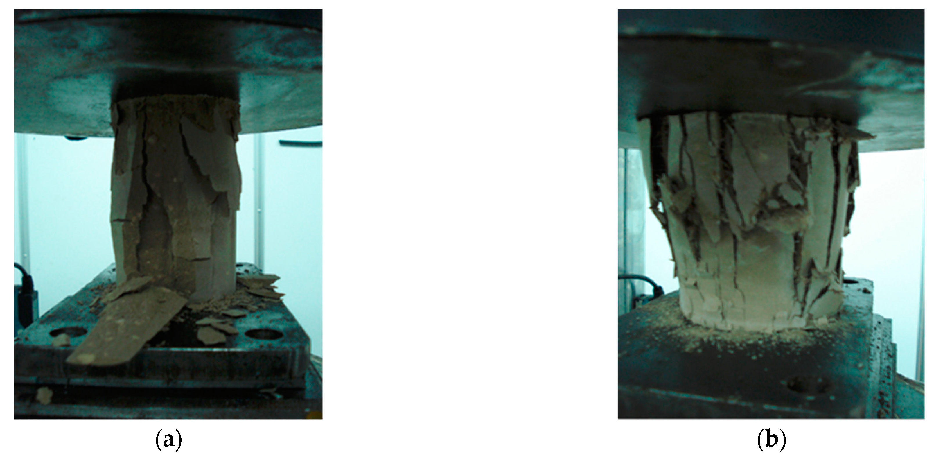
The compressive strength of the cement specimens was tested in 70 mm × 70 mm × 70 mm test molds; the slurry was injected into the test molds and placed in a curing box at an ambient temperature of 20 ± 2 °C and a humidity higher than 90%. The molds were removed after 1 d, 2 d, 3 d, and 7 d for compressive strength tests.
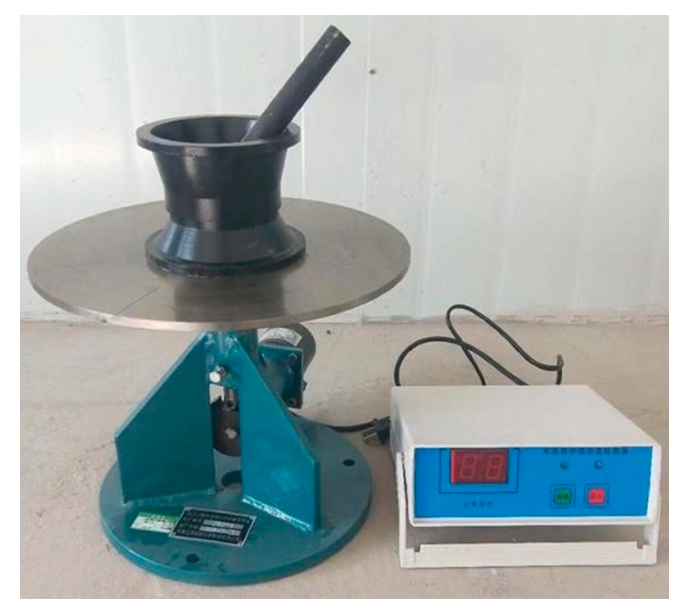
(5)
A water–cement ratio of 0.5 at 20 ± 2 °C was chosen for the development of the sealing material.

2.2.2. Influence of Different Cement Components on the Performance of Hole-Sealing Materials

Because the hydration reaction of ordinary silicate cement is slow and the setting time and starting strength time are long [15], it cannot meet the requirements of hydraulic fracture drilling and high-pressure water injection drilling, which affects the downhole construction progress. Thus, a special cement must be added to shorten the setting time of the cement slurry and accelerate the starting strength.
The results of the experiments and tests are shown in Table 1. With changes in the special cement content, the fluidity of the composite slurry fluctuated; the overall fluidity remained at 280–295 mm, which indicates good fluidity and injectability. Thus, the influence of the special cement on the fluidity of the composite slurry was ignored. The addition of the special cement decreases the setting time of the composite slurry; the initial setting time decreased from greater than 400 min to approximately 30 min. The time difference between the initial setting time and the final setting time was gradually shortened, which greatly accelerated the early strength of the material and improved the material strength. When the amount of special cement exceeded 25%, the chemical reaction between the two types of cement had a negative effect, hindering continued strength development, which decreased as the amount of special cement increased. For the combined effect of these three elements, the final choice was 20–25% of the special cement.

2.2.3. Effect of Expansion Agent Components on Material Properties

As shown in Table 2, the flow of the sealer material was significantly affected by an increase in the expander. The flow of the sealer material decreased from 282 mm to 171 mm owing to the reaction of the hydroxide generated by the reaction of the oxide expander with water and the components in the sealer material, which generated a colloid and caused a rapid decrease in the mobility of the sealer material [16].
Because the expansion agent continuously expands during setting of the composite slurry, and the expansion multiplier of the composite slurry is large, it is not appropriate to use the JC/T603-1995 “Cement Mastic Dry Shrinkage Test Method” to test the expansion of the slurry. We used a 1000 mL measuring cylinder to measure the expansion of the composite slurry every 20 min.
The specimens were naturally maintained after solidification; the dimensional changes of the specimens were measured at 1 d, 3 d, 7 d, and 14 d. No shrinkage or dry cracking was observed. Due to the reaction of the expander, there were many small independent bubbles inside the specimen, which effectively prevented the creation and penetration of cracks and enabled the material to maintain its overall integrity.
As can be seen from Table 2, with an increase in the content of the expansion agent, the fluidity of the cement slurry decreased from 282 mm to 171 mm, the initial setting time decreased from 71 min to 51 min, and the expansion ratio increased from 5% to 22%. When the content of the expansion agent was 4%, although the fluidity of the cement slurry decreased, it remained at 223 mm and the fluidity was still good. When the expansion agent content was higher than 4%, the fluidity of the cement slurry dropped to less than 200 mm; the initial setting time changed little, but the fluidity of the cement slurry became worse.
After the addition of the expansion agent, the compressive strength of the composite cement slurry slightly decreased; however, this did not have a significant impact. After many experiments with different blends, the final compound expansion agent admixture was chosen as approximately 4%.

2.2.4. Effect of Stabilizers on Sealing Material Performance

An inorganic stabilizer can improve the stability of the cement slurry, increase dispersion and uniformity, effectively stop water loss, and increase the penetration time into fissures in the coal-rock body, making the slurry more diffuse and improving the overall hole-sealing effect [17].
Stabilizers reduce water loss and improve the dispersion and stability of the slurry. However, the stability of the cement slurry did not increase with an increase in stabilizer content; when the content was greater than 2%, the overall performance of the cement slurry was reduced. Thus, approximately 2% of an inorganic stabilizer was added. A stabilizer eliminates water loss from cement grout owing to the influence of the expansion agent and has a slight influence on the fluidity and setting time of the cement slurry; however, it is not particularly obvious, and can be ignored.
After adding the stabilizer, the composite slurry had the following advantages:
(1)
The cement precipitation of the composite grout was lower, making the overall grout more uniform.
(2)
The water loss from the grout surface was reduced; the grout had high stability and could fully penetrate the microcracks in coal-rock pores, improving the sealing quality.
(3)
After adding the stabilizer, the overall structure of the slurry was dense, the mechanical strength was improved, and the slurry could better resist external loads.

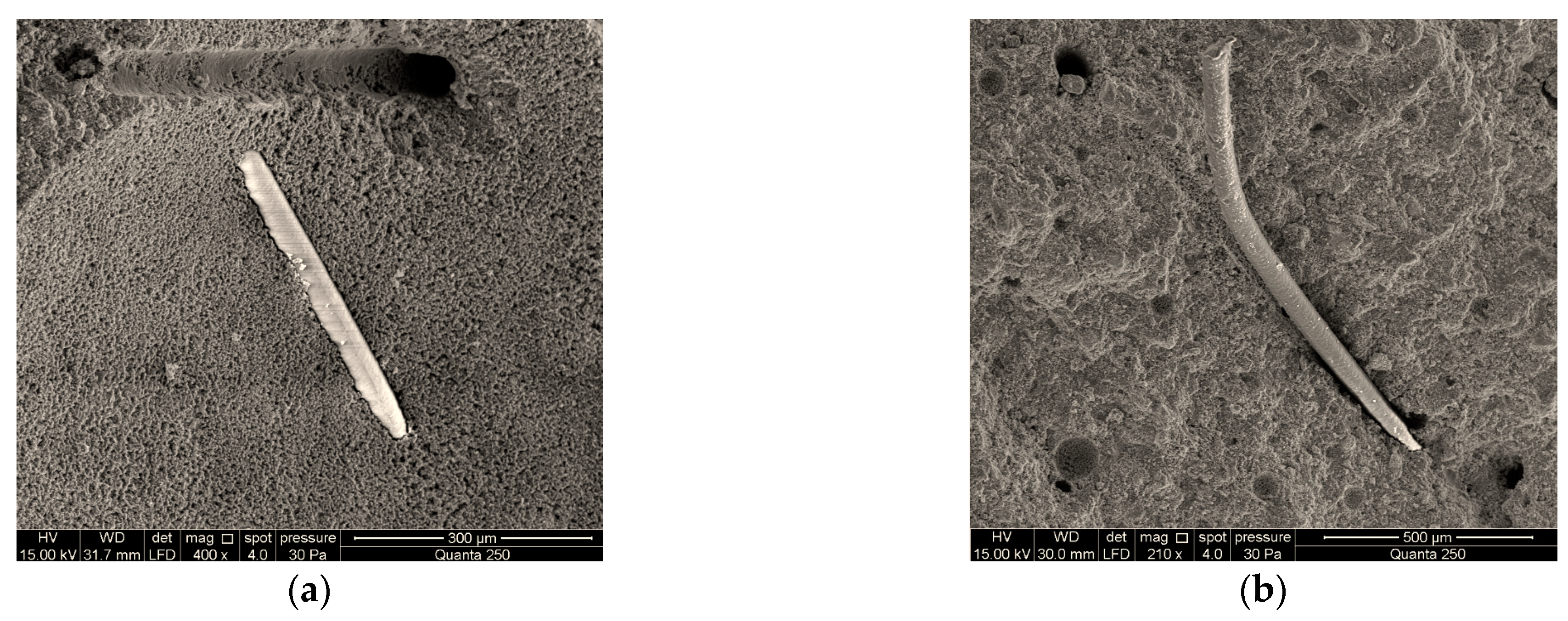
2.2.5. Effect of Fibers on Material Properties

It was demonstrated in many tests that the use of fibers to strengthen concrete can provide obvious crack resistance and toughening with a low fiber-volume content [18,19]. The addition of fibers to cement and concrete is common in practical engineering applications. The addition of fibers to cement grout has the following functions: crack resistance, seepage prevention, durability, impact resistance, and tensile resistance. Polyvinyl alcohol and basalt fibers are primarily used in engineering [20,21].
Because the elastic modulus of the fiber is higher than that of the cement body, when the cement body cracks under the action of an external load, the fiber begins to play a bonding role. When the material body reaches its maximum strength, the fiber plays a key role in preventing the destruction of the overall material. Thus, the mechanical properties of the cement matrix can be significantly improved with the addition of fibers.
Figure 2a,b shows the failure graphs of compressive strength tests of material specimens without fiber and with fiber, respectively. Their compressive effects can be clearly compared. The specimens without added fibers were destroyed as a whole; spalling was severe after reaching the maximum compressive strength. The specimens with added fibers reached the maximum compressive strength. Although cracks were produced, the specimens as a whole did not spall due to the cementing effect of the fibers. The specimens were severely compressed and deformed but maintained an excellent overall performance.
Table 3 shows the changes of fluidity of hole-sealing materials with different fiber lengths and contents. Because the fibers increased the surface area of the cement matrix, the fluidity of the cement slurry decreased with a gradual increase in the fiber content. The diameter of the fiber is only more than ten microns, requiring more cement paste wrapped on the fiber surface, which reduced the fluidity of the cement slurry. The addition of fiber had no direct effect on the solidification time of the cement slurry.
Fiber length is important. If the fiber is too short, it easily pulls out of the cement body when it is loaded, and the fibers have no benefit. If the fibers are too long, mixing the material becomes difficult.
Figure 3a,b shows microscopic analyses of the fibers using an FEI QuantaTM 250 environmental scanning electron microscope. It is observed that the 6 mm fibers are pulled out of the material matrix, leaving only a hole, whereas the 8 mm fibers are only partially pulled out. After a comprehensive analysis of the fiber content and microstructure, a fiber length of 8 mm was chosen to toughen the material matrix; the content was selected as 1.0% of the volume.

3. Bonding Performance Test of Hole-Sealing Materials

3.1. Cracking Pressure and Mechanical Property Test Method Selection

According to previous studies, in terms of the compressive strength, shear strength, and tensile strength of coal-rock masses, the compressive strength is approximately 2–5 times the shear strength. The tensile strength is 2–12% of the compressive strength, and the lowest of these mechanical properties. Thus, when a coal-rock mass is subjected to a load imposed by high-pressure water, the maximum tensile stress zone is the first to be destroyed; the micro-fissures in this region generate stress concentration under the action of stress. The tip of the micro-fissure has the highest stress concentration. When the stress concentration of the microcrack tip exceeds the tensile strength of the coal-rock mass, the microcracks at the tip begin to expand and extend [22].
According to contact stress theory, the maximum tensile stress area of the coal-rock body in the borehole is generally around the coal-rock body in the area directly subjected to high-pressure water impact. The tensile stress gradually decreases as the distance from the center of the directly impacted area increases. That is, the maximum tensile stress decreases with an increase in the radius from the central impact area. Outside the direct-impact area, the tensile stress decreases to zero, and the tensile stresses to which the coal-rock body is subjected are converted to compressive and shear stresses. Thus, during hydraulic fracturing, the primary micro-fractures in the coal-rock body are mainly subjected to the tensile stress of the high-pressure water, causing them to expand and extend. With the penetration of primary fractures, the coal-rock body away from the direct-impact area is subjected to the compressive and shear stresses of high-pressure water, producing secondary micro-fractures on the surface that continue to expand, forming a fracture network. Generally, the tensile strength of a coal body is approximately 1 MPa, but due to the interaction between the vertical pressure of the seam and the capillary pressure, site construction often requires a higher water pressure to fracture the micro-fractures of the coal body. Equation (1) describes the relationship between the fracture pressure of the coal seam and the depth of the coal seam endowment.
p f = 0.265 H + 3.5
where p f is the coal-seam fracturing pressure (MPa) and H is the depth of coal-seam fugacity (m).
From Equation (1), it is observed that the fracture initiation pressure of the coal seam is related to the burial depth. The greater the burial depth, the higher the initial fracture pressure. For coal seams with a burial depth greater than 1000 m, the borehole seal must withstand a pressure greater than 30 MPa; otherwise, the borehole will leak, affecting hydraulic fracturing and high-pressure water injection. In addition to a compressive strength of 30 MPa, the sealing material must resist the force exerted by the external load. Because the hole-sealing material is far from the direct-impact area of high-pressure water, it is subjected to high-pressure water mainly during fracturing construction. The bonding interface between the sealing material and the coal-rock body is mainly subjected to a compound stress consisting of shear stress and tensile stress generated by high-pressure water. Thus, the shear and tensile strengths of the bonding interface between the hole-sealing material and the coal-rock body must be tested to measure the bonding performance of the sealing material. The variable-angle shear (oblique shear) test method integrates the compression shear strength, tensile shear strength, and bending shear strength tests, and can accurately reflect the bonding performance of the sealing material and the coal-rock body to a certain extent and is more in line with actual sealing in a coal mine. The space utilization of the variable-angle shear specimen was high; the majority of the volume at the bond interface of the specimen was subjected to the maximum stress rather than the bending moment.
Figure 4 shows a schematic of the variable-angle shear (oblique shear) test method and the variable-angle shear test specimens and fixtures used in this study. The positive σ and shear stresses σ at the test specimen shear–damage interface were calculated using the following equations.
σ = F S cos α × 10     τ = F S sin α × 10
where σ is the positive stress (MPa); τ is the shear stress (MPa); F is the specimen damage load (kN); S is the area of the bonding interface (cm2); and α is the angle between the specimen and the horizontal plane.
When the angle between the test specimen and the horizontal plane is α < 40°, the test specimen may not be damaged according to the predetermined damage interface surface under the action of excessive α , but presents one-way compression shear damage. When the angle between the specimen and the horizontal plane is α > 65°, the tensile stress on the specimen increases, presenting tensile shear damage. Thus, a fixed horizontal angle of α = 50° was used for the variable-angle shear test.

3.2. Calculation Method for Fractional Dimension

For the bonding interface between the sealing material and the coal-rock body in the borehole, the traces can be considered to have a certain fractional dimensional structure, and the roughness of the bonding interface can be quantitatively described by the fractional dimensional value. This method can provide a comprehensive description of the corrugation and irregularity of the bonding interface between the sealing material and the coal-rock body and can determine the roughness of the coal-rock body in the borehole more accurately.
In this study, we chose the sectional vertical profile trace method to measure the length, L, of different traces with an unsynchronized distance, r. The fractional dimension of the interface was obtained after linear regression [23] and was used to measure the roughness of the bonding interface between the seal material and the coal-rock body in the borehole. Referring to the test apparatus of Sannma [23], the fractional dimensions of the coal-rock sections were measured using a homemade fractional dimension meter from the School of Materials Science and Engineering, Southeast University.
With n such intervals, it follows from the basic definition of the fractional dimension that the measured step, r, and curve length, L, are r = n L i n × L 0 ; L = n L i , where L i can be calculated using the following equation:
L i 2 = ( x ( i + 1 ) xi ) 2 + ( y ( i + 1 ) yi ) 2 .
The equation for the fractional dimension is
lgL = lg L 0 + ( 1 D ) lgr .
The measured r and D values for different values of n were introduced into Equation (3) and regressed in the lgL lgr coordinate system to obtain the D value. Compared to the linear regression model, y = ax + b , we obtain
D = 1 b .

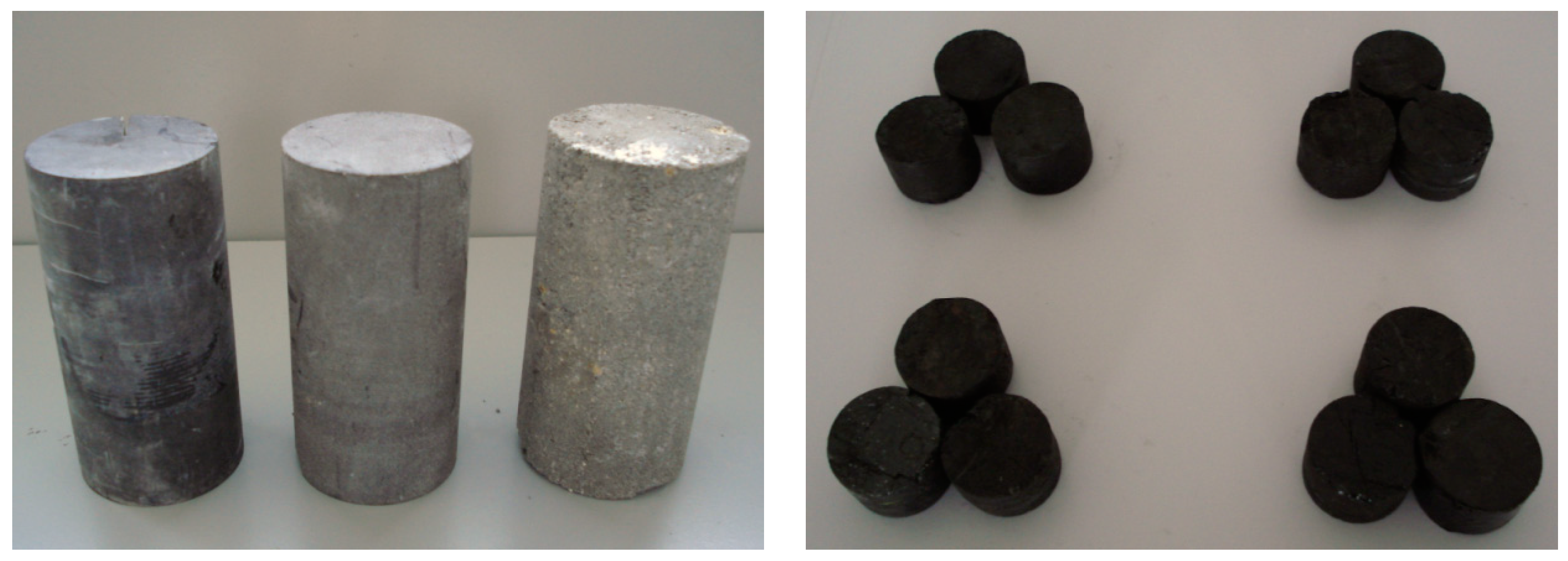
3.3. Specimen Cut after Fracturing

The test samples were processed as standard cylindrical specimens in accordance with the requirements of the test procedure of the Rock Mechanics Society; no artificial fissures were allowed during the specimen preparation. Cores were taken on a coring machine and cut flat using a cutter. The section was smoothed on a stone grinding machine. The height of the rock sample was 100 ± 5 mm and the diameter of the cylinder was 50 ± 2 mm; the height of the coal sample was 50 ± 5 mm. The processed rock and coal specimens are shown in Figure 5.
(1)
Fifteen rock samples (five samples from each type of rock) and 12 coal samples (three coal samples from each mine) that met the test requirements were collected and numbered.
(2)
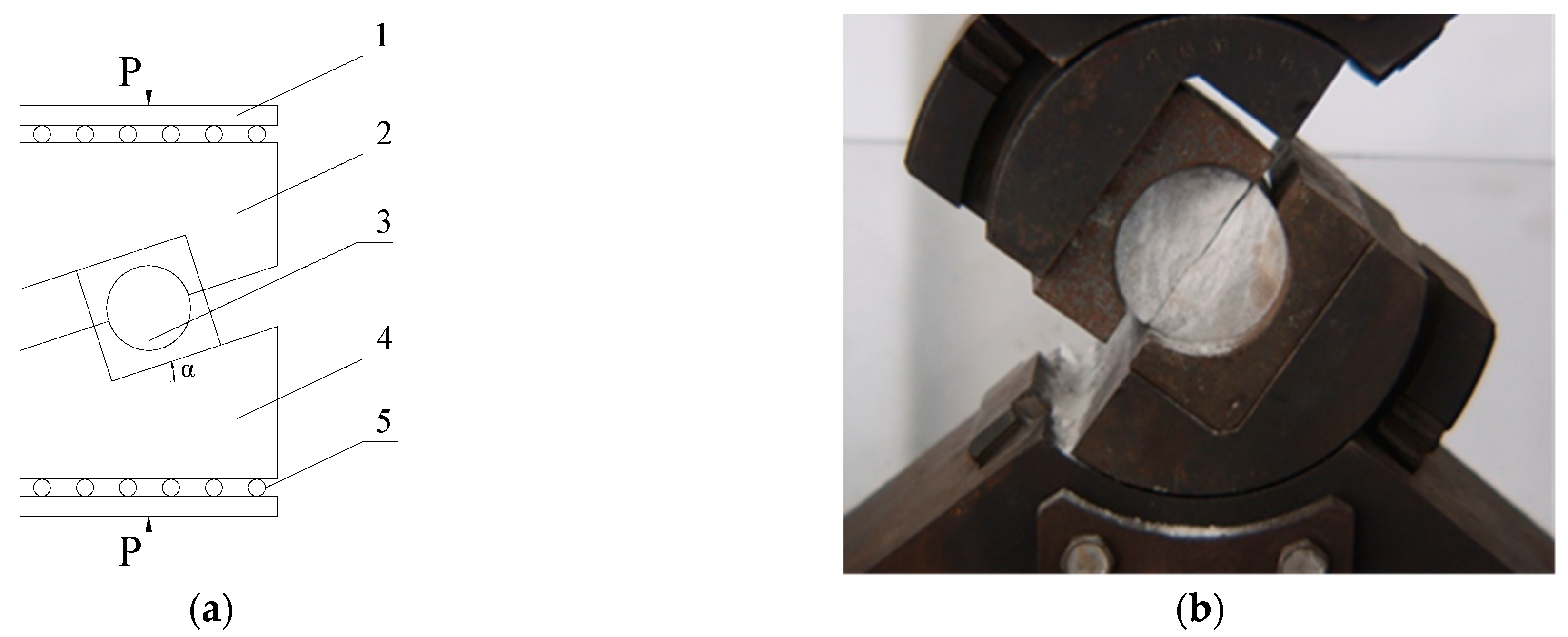
The selected coal-rock samples were sheared into two parts using a universal material-testing machine to perform oblique shear tests at a shear angle of α = 50°.
(3)
The shear surfaces of the coal-rock body samples sheared into two parts were moderately polished with sandpaper. After removing the broken particles, 30 rock samples and 16 coal block samples were selected after shearing (some coal samples were damaged after shearing; four samples were selected from each of the four coal samples), and the fractional dimension D of the shear surface of the coal-rock body was tested using a homemade fractional dimension meter.
(4)
Thirty rock samples and 16 coal samples were placed into the standard mold, and a new high-pressure-resistant drilling seal material was formulated with a suitable water–cement ratio. The seal material was injected into the standard mold and demolded after 3 d of standard maintenance; 46 samples of the combined seal material and coal-rock body were obtained.
(5)
A universal material-testing machine was used to perform a shear test with a shear angle of α = 50° on a sample of the bond between the sealing material and the coal-rock body to determine the minimum stress when the bond interface between the sealing material and the coal-rock body was broken.
(6)
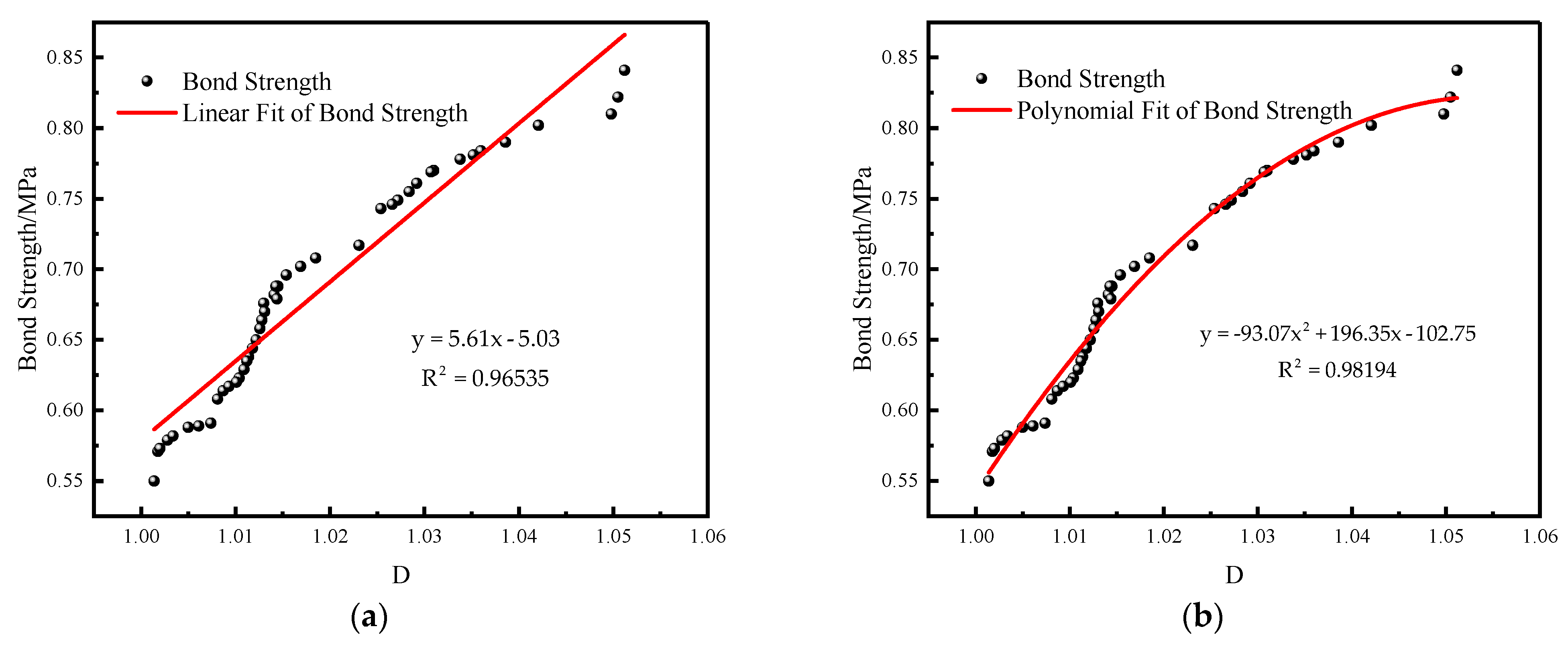
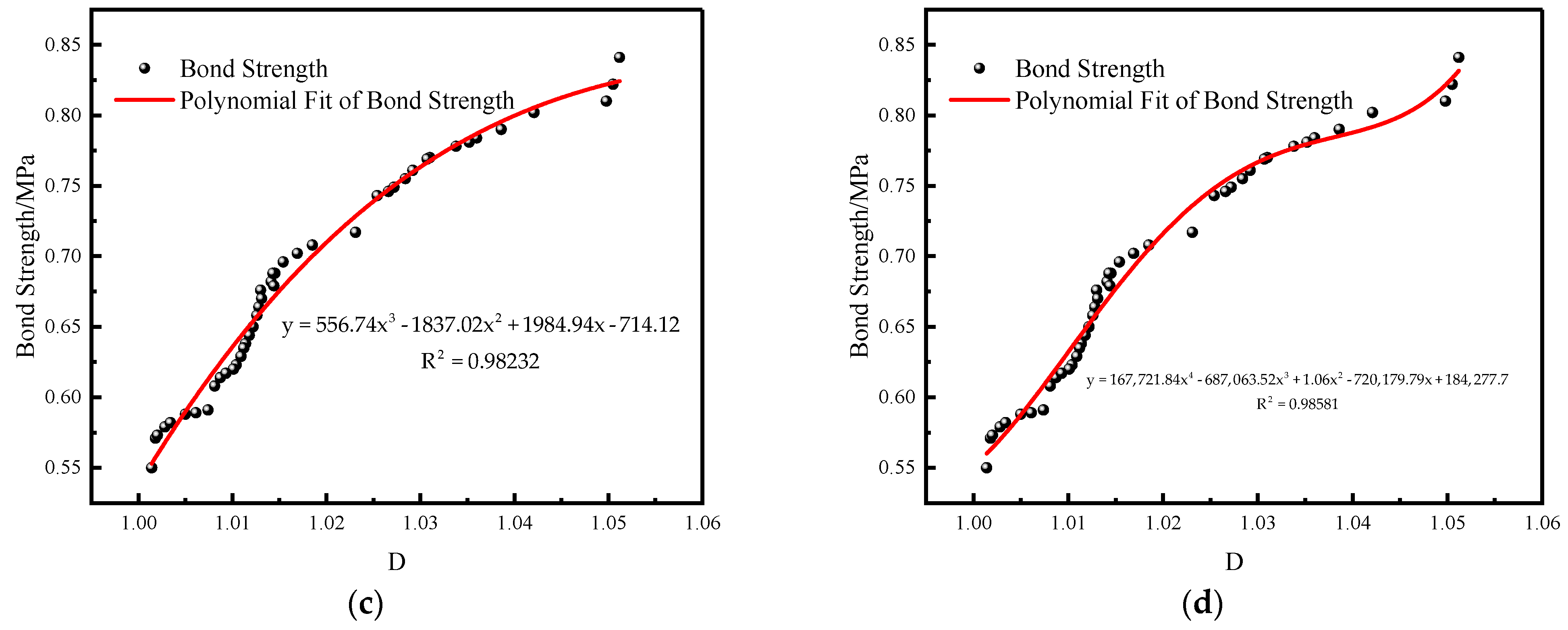
According to the measured fractional dimension, D, and the bond strength, a similar curve between the bond strength and roughness was fitted, and the function equation of the bond strength between the sealing material and the coal-rock body was analyzed.

3.4. Test Data and Curve-Fitting Function

The data on the applied load, shear strength, and calculated fractional dimensions of the coal-rock samples measured in the test are presented in Table 4.
The fractional dimension, D, was used as the horizontal axis and the bond strength, τ, was used as the vertical axis to make a graph, which was fitted with the primary linear function and the polynomial functions to obtain the fitted graph, the corresponding functional relationship, and the degree of fit.
Due to the complexity of the polynomial functions of the quintic function and above, the calculation is difficult and tedious, so this paper only selects the fitting with the primary linear function, the quadratic function, the trinomial function, and the quartic function, as shown in Figure 6a–d. The fitting degree of the primary linear function is 0.96335, the fitting degree of the binomial function is 0.98194, the fitting degree of the trinomial function is 0.98232, and the fitting degree of the quadrinomial function is 0.98581, it can be seen that the fitting degree of the polynomial is getting higher and higher.
In comparing the degree of fit of the fitted curves, although the quadrinomial function has the highest degree of fit, the coefficients of its function are more complicated and cumbersome to calculate. The degree of fit of the trinomial function is higher than that of the binomial, and the degree of fit is only 0.00038 less. The binomial function is easy to calculate; thus, the binomial function with a higher fitting degree and more convenient calculation was used as the fitting function for the fractional dimension and bond strength. Thus, the variation curve of the bond strength, τ, between the sealing material and the coal-rock body with the fractional dimension, D, follows the variation law of the binomial function:
y = 93.07 x 2 + 196.35 x 102.75

4. Conclusions

(1)
Considering the influence of different materials on the basic performance of the sealing materials, the integration of the setting time of composite cement slurry sealing materials, and the actual underground coal mine conditions, the best water–cement ratio was determined to be 0.5. The admixture of special cement was most suitable between 20% and 25%; the admixture of composite expansion agent was best at 4%. By adding 1% of 8 mm polyvinyl alcohol fibers, the surface area of the cement matrix was increased; the integrity and compressive strength of the material were increased due to the increased surface area of the cement matrix.
(2)
The variable-angle shear (oblique shear) test was used to integrate the compressive shear strength, tensile shear strength, and bending shear strength to accurately reflect the bonding performance of the sealing material and the coal-rock body. The results were in line with those from an actual coal mine. The oblique shear method with a fixed horizontal angle of τ = 50° was used to measure the bonding performance of the sealing material and the bonding interface of the coal-rock body, using the shear stress, τ, at the breaking interface.
(3)
The roughness of the coal-rock body around the borehole has a direct influence on the bonding strength of the sealing material, the bonding interface of the coal-rock body in the borehole, and the roughness of the coal-rock body. The measured fractional dimension, D, and the bond strength results were analyzed and fitted with a primary linear function and polynomial functions to obtain the fitted curves. Comparing the fitting degrees of the fitted curves, it was found that the change curve of the bond strength between the seal material and the coal-rock body with the fractional dimension, D, follows the change law of a binomial function.

Author Contributions

Conceptualization, X.L. and S.H.; methodology, X.L.; validation, T.W., W.Z. and J.Z.; formal analysis, S.H.; investigation, T.W., W.Z. and J.Z.; resources, X.L.; data curation, T.W., W.Z. and J.Z.; writing—original draft preparation, S.H.; writing—review and editing, X.L.; visualization, S.H.; supervision, X.L.; project administration, X.L.; funding acquisition, X.L. All authors have read and agreed to the published version of the manuscript.

Funding

This research was funded by the National Natural Science Foundation of China (grant no. 52174175, 52274078 and 52174073) and the Program for the Scientific and Technological Innovation Team at the Universities of Henan Province (grant no. 23IRTSTHN005).

Institutional Review Board Statement

Not applicable.

Informed Consent Statement

Not applicable.

Data Availability Statement

Not applicable.

Conflicts of Interest

The authors declare no conflict of interest.

References

  1. Zheng, K. Permeability improving technology by sectional hydraulic fracturing for comb-like long drilling in the floor of crushed and soft coal seam with low permeability. J. Min. Saf. Eng. 2020, 37, 272–281. [Google Scholar]
  2. Zhang, C.; Yan, J.; Li, S. Experimental study on dynamic sealing of mucilage material in gas extraction borehole. J. Min. Saf. Eng. 2022, 39, 1033–1040. [Google Scholar]
  3. Wang, S. A new pressure maintaining and sealing technology for gas drainage borehole. Saf. Coal Mines 2021, 52, 61–66. [Google Scholar]
  4. Yang, W.; Huo, Z.; Shu, L. Analysis of the whole process of grouting sealing for gas extraction drilling hole sealing section. Saf. Coal Mines 2021, 52, 1–6. [Google Scholar]
  5. Liu, A.; Ju, W.; Zhang, Z. Key factors in hole-sealing and pressure-relief failure of hydraulic fracturing straddle packer in coal mine. Eng. Fail. Anal. 2023, 149, 107243. [Google Scholar] [CrossRef]
  6. Klishin, S.V.; Klishin, V.I. Packer Sealing–Wellbore Interaction in Hydraulic Fracturing in Coal Seams. J. Min. Sci. 2020, 56, 547–556. [Google Scholar] [CrossRef]
  7. Xiao, Q.; Yu, X.; Feng, K. Research and application of “double-sealing and single-grouting” hole sealing technique with pressure in Longmen Gorge South Coal Mine. China Coal 2020, 46, 52–56. [Google Scholar]
  8. Pakravan, H.R.; Latifi, M.; Jamshidi, M. Hybrid short fiber reinforcement system in concrete: A review. Constr. Build. Mater. 2017, 142, 280–294. [Google Scholar] [CrossRef]
  9. Furlan, S.; Hanai, J. Shear behavior of fiber reinforced concrete beams. Cem. Concr. Compos. 1997, 19, 359–366. [Google Scholar] [CrossRef]
  10. American Concrete Institute. ACI 546.3R-14: Guide to Materials Selection for Concrete Repair; American Concrete Institute: Indianapolis, IN, USA, 2014. [Google Scholar]
  11. Li, S. Durability and Bond of High-Performance Concrete and Repaired Portland Cement Concrete; University of Connecticut: Storrs, CT, USA, 1997. [Google Scholar]
  12. Tabor, L.J. The Evaluation of Resin Systems for Concrete Repair. Mag. Concr. Res. 1978, 30, 221–225. [Google Scholar] [CrossRef]
  13. Li, C.; Ke, L.; Chen, Z. Experimental study and numerical simulation for bond behavior of interface between CFRP and steel. Acta Mater. Compos. Sin. 2018, 35, 3534–3536. [Google Scholar]
  14. GB1346-2001; Test Methods for Water Requirement of Normal Consistency, Setting Time and Soundness of the Portland Cements. GAQSIQ: Beijing, China, 2001.
  15. GB/T2419-2005; Method for Determining the Flow of Cementitious Sand. National Institutes of Health: Bethesda, MD, USA, 2005.
  16. Gou, M.; Guan, X.; Zhang, A. Study on a New Cement-Based Plugging Grouting Material. Coal Technol. 2007, 119–121. [Google Scholar] [CrossRef]
  17. Feng, Q.; Jia, F.; Peng, Z. Preparation, characterization, and evaluation of suspension stabilizer for low-density cement slurry for cementing. J. Appl. Polym. Sci. 2022, 139, e53058. [Google Scholar] [CrossRef]
  18. Nassiri, S.; Chen, Z.; Jian, G. Comparison of unique effects of two contrasting types of cellulose nanomaterials on setting time, rheology, and compressive strength of cement paste. Cem. Concr. Compos. 2021, 123, 104201. [Google Scholar] [CrossRef]
  19. Kim, S.; Park, C. Flexural Behavior Characteristics of High Performance Slurry Infiltrated Fiber Reinforced Cementitious Composite with Respect to Exposure to High Temperature. J. Korea Concr. Inst. 2019, 31, 139–146. [Google Scholar] [CrossRef]
  20. Yang, G.; Dong, Z.; Bi, J. Experimental study on the dynamic splitting tensile properties of polyvinyl-alcohol-fiber-reinforced cementitious composites. Constr. Build. Mater. 2023, 383, 131233. [Google Scholar] [CrossRef]
  21. Gomes, T.A.; de Resende, T.L.; Cardoso, D.C.T. Shear-transfer mechanisms in reinforced concrete beams with GFRP bars and basalt fibers. Eng. Struct. 2023, 289, 116299. [Google Scholar] [CrossRef]
  22. Liu, J.; Nie, Z.; Yu, B. Analysis of the mechanism and influencing factors of supercritical carbon dioxide on coal permeability enhancement. Coal Sci. Technol. 2023, 51, 204–216. [Google Scholar]
  23. Sannma, V.E. Fractal characterization of fracture surfaces in concrete. Eng. Fraerure Meehanies 1990, 35, 47–53. [Google Scholar]
Figure 1. Flow table to determine the mortar fluidity, consistency, and setting time of cement.
Processes 11 02270 g001
Figure 2. (a) Compression test at 1 d; (b) compression test at 3 d.
Processes 11 02270 g002
Figure 3. (a) Scanning electron micrograph of 6 mm fiber; (b) scanning electron micrograph of 8 mm fiber.
Processes 11 02270 g003
Figure 4. (a) Diagram of variable-angle shear test (1—steel spacer plate, 2—fixture upper seat, 3—test piece, 4—fixture lower seat, 5—rollers); (b) fixture of the variable-angle shear.
Processes 11 02270 g004
Figure 5. Diagram of rock specimens and coal samples.
Processes 11 02270 g005
Figure 6. (a) Linear function fitting of the fractal dimension and adhesive strength; (b) binomial function fitting of the fractal dimension and adhesive strength; (c) trinomial function fitting of the fractal dimension and adhesive strength; (d) quadrinomial function fitting of the fractal dimension and adhesive strength.
Processes 11 02270 g006aProcesses 11 02270 g006b
Table 1. Influence of swelling-agent content on materials.
Ordinary Silicate
Cement Content/%
Special
Cement
Content/%
Flow/mmSolidification Time/minCompressive Strength/MPa
Initial CondensationFinal Condensation1 d3 d
9552794106646.88.8
901028123034213.016.7
851528811815917.922.5
8020293829822.831.3
7525292728824.132.7
7030292607623.432.1
6535291506322.629.8
6040287384621.828.8
5545282283420.226.5
Table 2. Influence of swelling-agent content on materials.
Amount of Expansion Agent Added/%Flow/mmSolidification Time/minExpansion Multiplier/%
Initial CondensationFinal Condensation
128271835
2261677710
3245627015
4223556116
5194545718
6171515522
Table 3. Fluidity of hole-sealing materials with different fiber lengths and contents.
Length/mmFiber Content/%
0.51.01.52.0
6294270242205
8300278250215
12305285256225
Table 4. Test results.
Sample NumberApplied Load/kNBond Strength/MPaDSample NumberApplied Load/kNBond Strength/MPaD
Coal sample 12.000.6001.0076Rock sample 84.950.7781.0338
Coal sample 21.930.5881.0050Rock sample 94.540.6821.0141
Coal sample 32.110.6381.0114Rock sample 104.950.7551.0284
Coal sample 41.860.5791.0028Rock sample 114.470.6791.0144
Coal sample 52.080.6231.0104Rock sample 124.470.6961.0154
Coal sample 61.950.6141.0087Rock sample 134.700.7021.0169
Coal sample 71.850.5711.0018Rock sample 144.290.6641.0128
Coal sample 82.110.6441.0118Rock sample 154.670.7171.0231
Coal sample 91.790.5501.0014Rock sample 164.520.6881.0143
Coal sample 102.030.6201.0101Rock sample 175.100.7901.0386
Coal sample 111.890.5911.0074Rock sample 184.900.7491.0272
Coal sample 121.870.5731.0020Rock sample 194.300.6701.0131
Coal sample 132.020.6171.0093Rock sample 204.940.7611.0292
Coal sample 141.900.5821.0034Rock sample 215.040.7691.0307
Coal sample 151.960.6081.0081Rock sample 225.500.8411.0512
Coal sample 161.910.5891.0061Rock sample 234.300.6291.0109
Rock sample 15.360.8021.0421Rock sample 244.820.7461.0266
Rock sample 24.220.6351.0112Rock sample 255.140.7841.0360
Rock sample 34.120.6501.0122Rock sample 265.180.7811.0352
Rock sample 45.410.8221.0505Rock sample 274.220.6581.0126
Rock sample 54.530.6881.0145Rock sample 285.310.8101.0498
Rock sample 65.160.7701.0310Rock sample 294.870.7431.0254
Rock sample 74.340.6761.0130Rock sample 304.580.7081.0185
Disclaimer/Publisher’s Note: The statements, opinions and data contained in all publications are solely those of the individual author(s) and contributor(s) and not of MDPI and/or the editor(s). MDPI and/or the editor(s) disclaim responsibility for any injury to people or property resulting from any ideas, methods, instructions or products referred to in the content.

