
Mechanical Behavior and Low-Cycle Fatigue Performance of a Carburized Steel for GTF Engines

1
Aero Engine Corporation of China, Beijing 100097, China
2
Institute for Aero Engine, Tsinghua University, Beijing 100084, China
*
Author to whom correspondence should be addressed.
Processes 2023, 11(4), 1275; https://doi.org/10.3390/pr11041275
Submission received: 16 March 2023
/
Revised: 8 April 2023
/
Accepted: 11 April 2023
/
Published: 20 April 2023
(This article belongs to the Special Issue Advances in Green Propulsion Engine and Environmental Pollution Control)
Abstract
:Using nanoindentation technology to analyze the hardness and elastic modulus distributions of the local microzones within materials, it can be determined that the case-carburized specimen is a composite of the carburized case and the pseudo-carburized material in the core. The overall mechanical behavior of the case-carburized material is much closer to that of the completely carburized material, indicating that the carburized case dominates the case-carburized material. Stress fatigue tests conducted on carburized tubular specimens, pseudo-carburized solid specimens, and case-carburized solid specimens showed that the fatigue performance of the completely carburized material is slightly lower than that of the pseudo-carburized specimens due to lower plasticity. However, the fatigue performance of the case-carburized specimens is significantly better than that of the two homogeneous materials. This could be attributed to the graded material behavior and the larger compressive residual stress in the carburized case, which are the primary positive factors for improving the fatigue life of case-carburized materials. SEM fractographs revealed that the fatigue nucleation in the case-carburized specimen initiates from the transition zone rather than from the surface of the specimens as observed in the homogeneous materials. Low-cycle fatigue evaluation of ultra-high-power gear transmission systems should focus on the influences of the carburized case.
1. Introduction
As the Pratt & Whitney geared turbofan (GTF) engine matures, it is expected that ultra-high-power reduction gear systems will become more prevalent in the rotor system of aeroengines. However, gear design must address low-cycle fatigue as the primary failure mode, as bending loads at the tooth root of gears are much larger in the rotor system than in ordinary transmission systems. To improve the fatigue resistance and service life of parts generally, carburization is widely used in aeroengine reduction gearboxes [1,2]. Therefore, it is important to quantify the mechanical behavior and low-cycle fatigue performance of carburized parts.
Carburization is a process of case hardening where the specimens to be carburized are placed in a kerosene atmosphere and heated to 850∼950 °C. This allows carbon atoms in the environment to infiltrate into the materials, typically low-carbon steels that are readily fabricated into mechanical parts. The gradient in the carbon content beneath the surface of the parts results in a corresponding gradient in hardness, creating a strong and hardened case on the parts, whereas the core of the parts remains soft and tough.
Meanwhile, carbon atoms enter the surface of the parts and form residual stress [3] due to the sequence of microstructure transformations upon quenching. Generally, this residual stress can significantly affect the mechanical properties of carburized parts, including hardness, yield strength, tensile strength, and fatigue performance. As a result, the distribution of residual stress along the depth of carburized specimens has been widely studied. It has been found that the surface of such specimens has residual compressive stress, which reaches the maximum value at some distance from the surface of the specimens and then gradually decreases with depth. Eventually, it reaches a stable value of residual tensile stress [4,5]. However, residual stress distributions can be more complex within carburized parts because of temperature gradients and retained austenite [6], thus making accurately characterizing the effect of residual stress on the fatigue performance in carburized parts difficult.
To properly design parts that require carburization to achieve high wear and fatigue strength, such as gears and shafts, the effects of case depth, retained austenite, hardness, and residual stress on fatigue performance in case-carburized materials have been widely investigated in [7,8,9,10]. It has been found that fatigue cracks always initiate underneath the carburized case at a very early stage of fatigue life and subsequently grow predominantly into the core material regardless of the environment and stress level, and the carburized materials show considerably higher fatigue strength compared with the untreated materials [11,12]. Because the graded material behavior and the residual stress make mechanical analysis of the case-carburized parts considerably more difficult, life models based on nominal stress or nominal strain are still used in practice, leading to much more conservative treatments being necessary for safety. Inevitably, this traditional approach contradicts the requirement to pursue the smallest size and weight in engineering design, particularly in the aerospace and aeroengine domains.
In summary, carburization of mechanical parts is popular for generally improving the fatigue performance of parts. However, how to characterize the mechanical properties of carburized materials and to quantify the effects of residual stress induced by carburization on the fatigue life of carburized mechanical parts remain open questions. Additionally, methods for accurately predicting the fatigue life of carburized parts based on the fatigue performance of homogeneous materials have not been established. Therefore, in the present paper, the effects of carburization on the mechanical properties and fatigue performance of the low-carbon steel 18Cr2Ni4WA are investigated through indentation tests, tensile tests, and fatigue tests using solid and thin-walled tubular specimens after carburizing and solid specimens subjected to pseudo-carburizing. Here, pseudo-carburizing is a simulated carburization procedure that is performed without the carburizing medium [13].
2. Materials and Methods
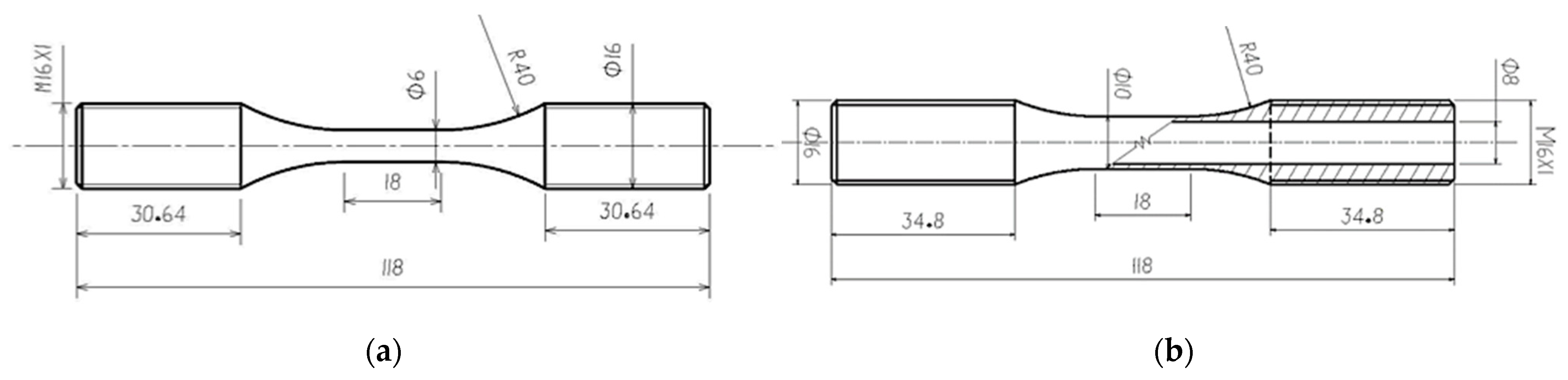
18Cr2Ni4WA is a low-carbon steel with the following chemical composition (in wt%): 0.16 C, 0.19 Si, 0.33 Mn, 1.55 Cr, 4.22 Ni, 0.97 W, 0.005 S, 0.01 V, 0.01 Mo, 0.008 P, 0.009 Ti, 0.04 Cu-Fe (balance). After carburizing, the surface of parts forms a carburized case that has a higher hardness. To characterize the mechanical properties and fatigue performance of the carburized 18Cr2Ni4WA steel, round bars with a diameter of 18 mm were produced using virgin material. Solid specimens with a cylindrical gauge of 18 mm in length and 6 mm in diameter, as well as tubular specimens with a similar gauge length, 10 mm external diameter, and 8 mm inner diameter, as shown in Figure 1, were then machined and subjected to carburization and pseudo-carburization, respectively.
The process of carburization used in this paper included four stages. First, the carburized specimens were subjected to a kerosene atmosphere at a temperature of 850 °C with a carbon content of 0.5%, held for 2 h for heat treatment, then heated to the carburizing temperature of 930 °C with an increased carbon content of 1.2%, and held for 6 h for the forced carburizing. Next, the carburized specimens were held for 4 h for the diffusion carburizing with a carbon content of 0.98% without a temperature change. Finally, the specimens were cooled at room temperature. The pseudo-carburizing process was a simulated carburization procedure performed with a carbon content of 0%.
3. Results and Discussions
3.1. Static Mechanical Properties
The nanoindentation test has become a wildly used method for investigating the mechanical properties in the microzone of a material [14,15,16,17]. For case-carburized materials, obtaining appropriate parameters of mechanical properties through tensile and compressive tests is very difficult because the elastic–plastic response varies with the depth from the surface of the specimens. The microindentation technique based on hardness measurements is considered to be an inexpensive, non-destructive, and simple method for obtaining a material’s mechanical behavior parameters, especially for gradient materials such as carburized materials [18,19,20].
3.1.1. Distributions of Hardness and Elastic Modulus
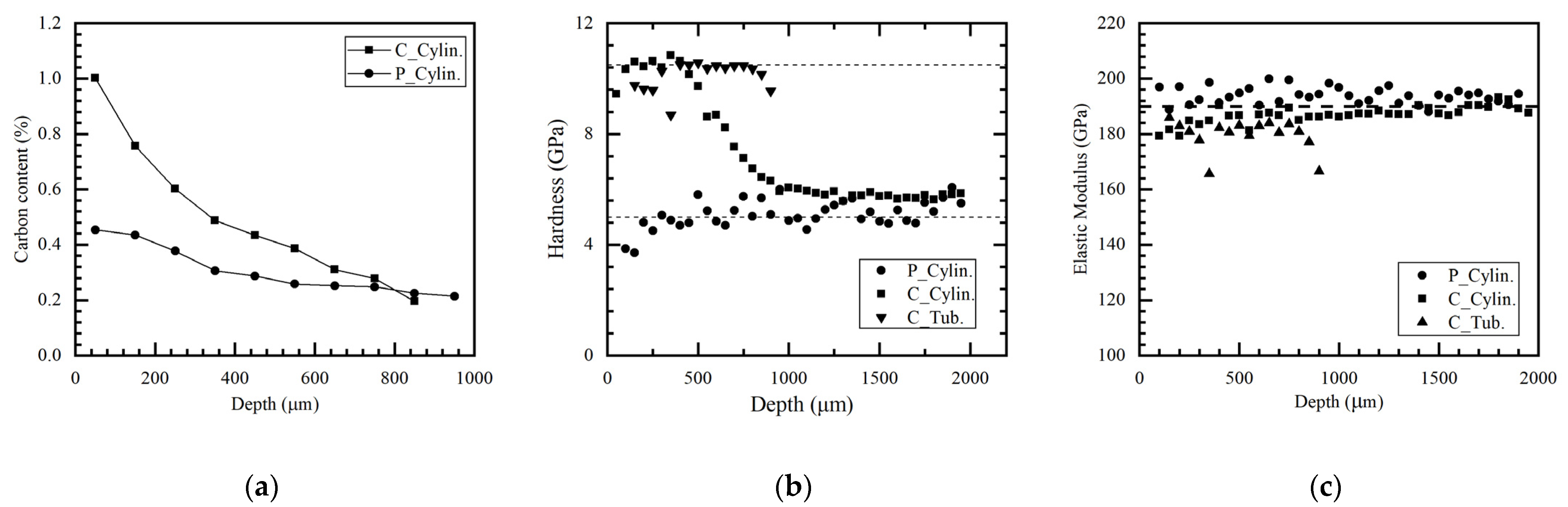
Three types of specimens were obtained including case-carburized cylindrical specimens (C.Cylin.), carburized tubular specimens (C.Tub.), and pseudo-carburized cylindrical specimens (P.Cylin.). In general, carburization improves the hardness of the surface of the specimens by increasing the carbon content of the surfaces to form martensite with a high carbon content; however, the carbon content of pseudo-carburizing specimens still remains the same value as that of the virgin material. Figure 2a,b show the distributions of carbon content and Brinell hardness within different specimens separately. In this study, the hardness of the specimens was measured using Agilent’s Nanoindenter G200 with a Berkovich indenter with the continuous stiffness method. It can be observed that the distribution of the carbon content is similar to that of the hardness for the solid specimens after carburizing, and that the maximum hardness of the carburized steel is about 10.5 GPa, which is almost independent of the shape of the specimens. For the case-carburized solid specimen, the hardness is significantly reduced with depth and is approximately a linear function of depth when the depth exceeds 350 μm, while the hardness at depths beyond approximately 800 μm tends to stabilize, approaching that of the pseudo-carburized solid specimens, at approximately 5.0 GPa. Therefore, the thickness of the carburized case for the case-carburized solid specimen can be estimated as 800 μm.
A load–displacement curve (often called P-h curve) at every indenter can be obtained during the nanoindentation tests. Based on the P-h curves, the elastic modulus of the local microzone material of the specimens can be conducted through Dao’s method [21], a sort of reverse analysis algorithm of nanoindentation. Figure 2c shows the distributions of the elastic modulus of the different specimens; it is obvious that the elastic modulus of the carburizing steel is almost not affected by the carburization and the depth from the surface of the specimen. The average value of the calculated elastic modulus is about 190 GPa. According to the distributions of hardness and elastic modulus, the solid specimens can be considered as a combination of the completely carburized case material and the pseudo-carburized core material. Furthermore, the hollow tubular specimens can be considered a completely carburized steel used to investigate the approximate mechanical properties and fatigue performance of the carburized case, while the pseudo-carburized cylindrical specimens can be used to investigate the mechanical properties and fatigue performance of the materials in the core of the case-carburized solid specimen.
Note that for the carburized specimens in Figure 2b, the hardness of the surface significantly decreases within a depth of less than 200 μm due to more retained austenite (RA) in the surface, as shown in Figure 3a, which indicates that the gradient in carbon content within the specimen results in not only a gradient hardness but also a graded change in microstructure. In the high-carbon-content area of the case, the microstructure consists mainly of acicular martensite and retained austenite, as well as carbides, whereas in the core region of the specimens more bainite and ferrite remain due to the low carbon content as shown in Figure 3b,d.
3.1.2. Distribution of Residual Stress
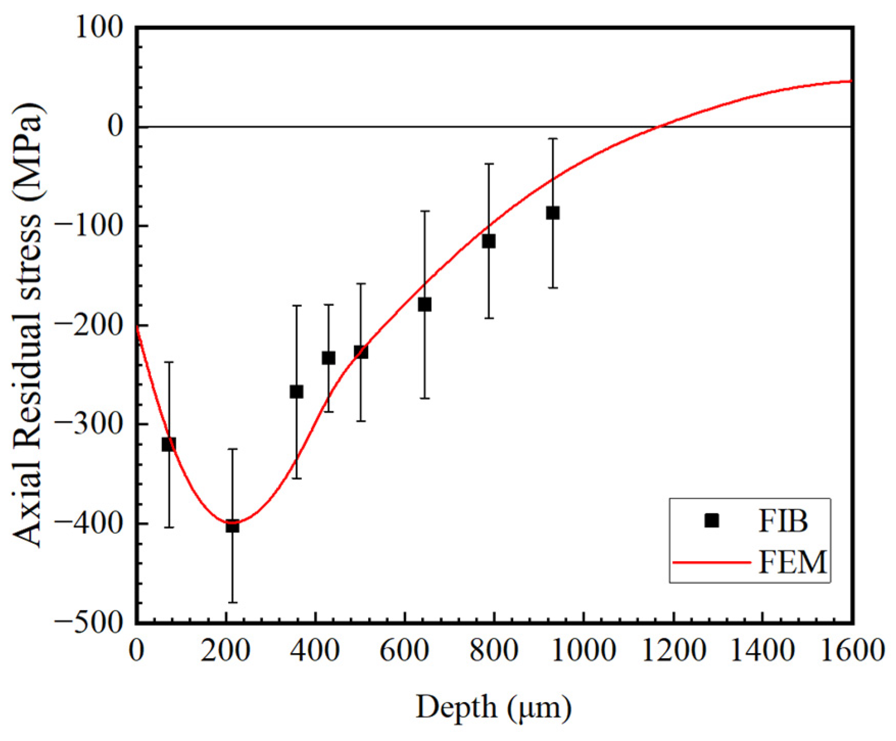
Carburization can introduce residual compressive stress into the case of solid specimens [22]. In this study, the distribution of residual stresses along the depth of the carburized solid specimen was measured through the milling method based on a focused ion beam (FIB) system. As shown in Figure 4, the maximum residual compressive stress in the carburized case is about 402 MPa, which is about 50% of the yield stress of the pseudo-carburized material in the core (shown in Figure 5), and it occurred at a depth of about 215 μm from the surface of the solid specimen. The residual stress tends to zero in the region of 1 mm depth and will then become the tensile stress in the core region of the specimen from consideration of force balances. Therefore, there is almost always residual compressive stress in the whole carburized case.
Residual stress will generally change the mechanical properties of parts and then seriously affect the service life of parts, particularly when the residual stress on the surface of parts is larger. As shown in Figure 2b,c, however, these distributions of hardness and elastic modulus may not be significantly affected by the residual stress within the solid specimens.
3.1.3. Stress–Strain Curves
The mechanical properties of a homogeneous material are typically measured through tensile or compressive tests, in which the nominal stress in the gauge of the specimen is the true stress of the material. The tubular specimen and the pseudo-carburized solid specimen are approximately homogeneous, and there is almost no residual stress within the specimens. However, the case-carburized solid specimen is a nonuniform material because the microstructures in the core are significantly different from those in the case within the specimen [23], which can be considered a combination of the carburized steel in the case and the pseudo-carburized steel in the core. In addition, on the surface of the specimen, there is higher residual compressive stress, whereas there is residual tensile stress in the core. Therefore, the nominal stress–strain curve obtained from the tensile test cannot characterize the true mechanical behavior but rather only the average properties of the graded materials within the carburized solid specimen.
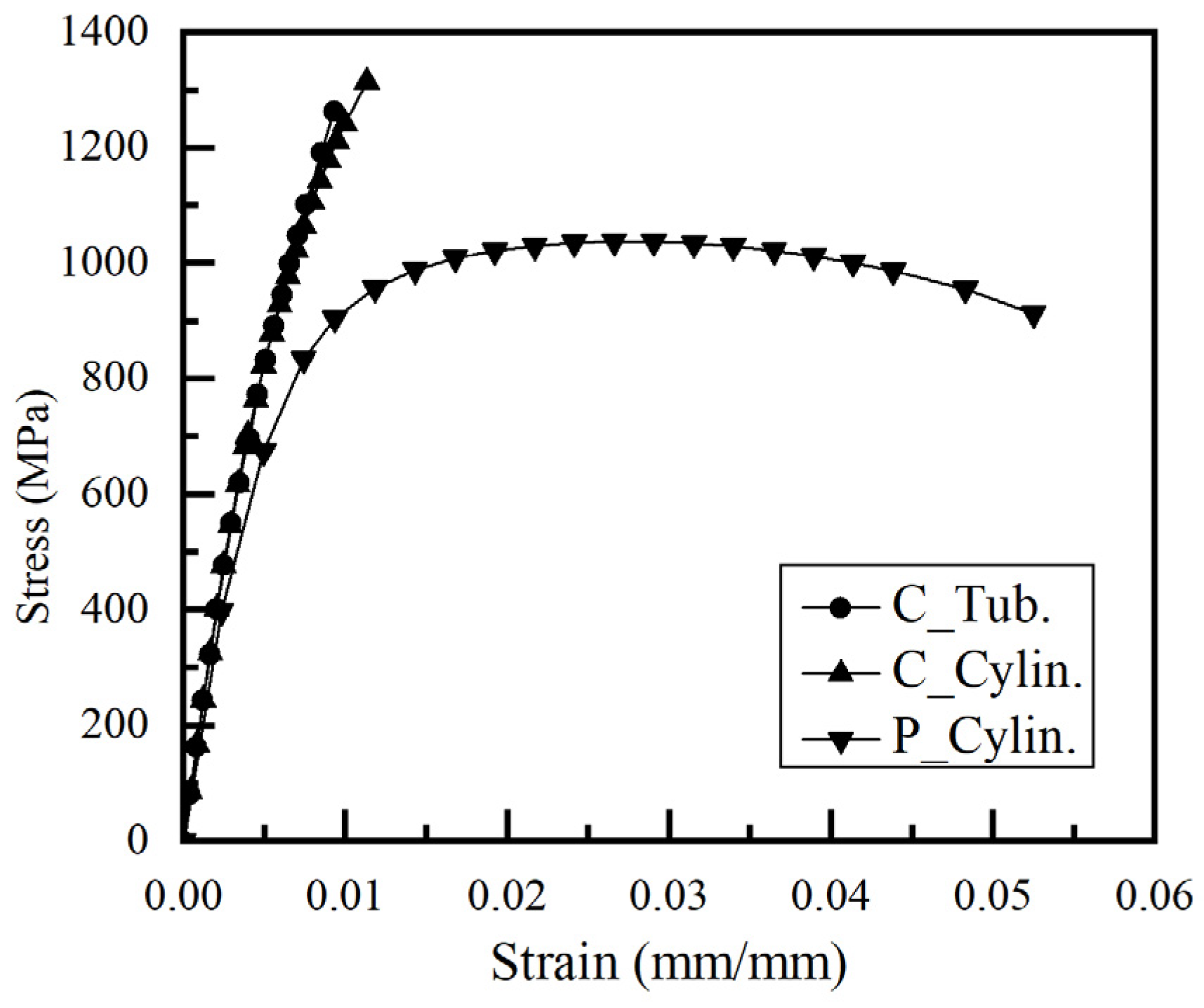
Stress–strain curves of three types of specimens obtained from the tensile tests on an MTS809 hydraulic servo tester are shown in Figure 5. The elastic moduli of the different specimens are almost consistent, approximately 197 GPa, which is a less than 3.1% difference, and almost not affected by the material state. Comparing the macrotensile test and indentation test, the difference between the elastic modulus values is less than 5.0%. The monotonic tensile properties are listed in Table 1.
Note that the nominal stress–strain curve of the case-carburized cylindrical specimen is very similar to that of the carburizing tubular specimen and is almost free of plastic deformation, as shown in Figure 5, indicating that the carburized case will dominate the deformation in monotonic loading. Nevertheless, the values of fracture stress and fracture strain on the case-carburized specimen, 1313 MPa and 1.13%, respectively, are larger than those of the completely carburized tubular specimen, indicating that the strength and toughness of the carburized cylindrical specimen have been improved compared with those of the material in the carburized tubular specimen. However, the material after pseudo-carburization becomes more ductile, and its fracture strains are greater than 5.0%. In short, the mechanical behavior of carburized parts can be deduced from that of simple specimens, that is, the carburized case will dominate the deformation and fracture of carburized parts, and its damage under monotonic tensile loads is also primarily a brittle fracture.
3.2. Fatigue Tests and Properties
Higher hardness and brittleness are the main characteristics of the mechanical properties of carburized steel; the former can improve the wear and fatigue resistance of the material, whereas the latter will result in a decrease in the fatigue performance of the material. As shown in Figure 5, the mechanical behavior of carburized parts is almost linear and is closer to that of the completely carburized steel. Fatigue tests for carburized materials are conducted with stress controlled rather than strain controlled due to higher brittleness. To quantify the fatigue properties of the carburized part, fatigue tests for the carburized thin-walled tubular specimens, the pseudo-carburized solid specimens, and the carburized solid specimens were performed with stress controlled with a completely inverted load on an MTS809 hydraulic servo tester.
The stress–life curves (often called S-N curves) of the pseudo-carburized steel and the carburized steel are shown in Figure 6, including the tubular and solid specimens after carburization and the solid specimens after pseudo-carburization. In general, the S-N curves can be characterized through the Basquin model as follows:
where is the number of fatigue cycles, is the stress amplitude of the applied load, and and are model parameters.
Because both the carburized tubular specimens and the pseudo-carburized solid specimens can be approximately considered as uniform materials, which ensures that the nominal stress in the specimens is uniaxial and is equal to the true stress of the specimens for the uniaxial fatigue tests, the S-N curves can reflect the fatigue properties of completely carburized steel and pseudo-carburized steel and can generally be characterized by the conventional Basquin model, for which the parameters are listed in Table 2. Due to concern about the LCF performance of materials, can be calculated according to the Basquin equation (Equation (1)) occurring at cycles.
Note that, as shown in Figure 6, the fatigue life of the completely carburized steel is slightly lower than that of the pseudo-carburized base metal due to its worse plasticity, indicating that the carbon content during carburization cannot improve the fatigue properties of the low-carbon steel 18Cr2Ni4WA. Meanwhile, it can clearly be observed that the fatigue performance of the case-carburized solid specimens is significantly higher than that of the carburized tubular specimens and pseudo-carburized specimens. As mentioned earlier, the carburized cylindrical specimen can be considered as a combination of the carburized steel in the case and the pseudo-carburized steel in the core, while the overall mechanical behavior of the case-carburized material only shows slightly better ductility than the completely carburized steel, as shown in Figure 5. Moreover, note that the amplitude of the residual compressive stress in the carburized case of the solid specimen has exceeded the fatigue strengths of the uniform materials, as shown in Table 2; thus, the material fatigue damage on the surface might be delayed, and the overall fatigue performance of the specimens is improved. Therefore, both the graded mechanical behavior and residual stress are positive factors in improving the fatigue life of the case-carburized part.
Due to the inhomogeneous mechanical behavior of the case-carburized material, the nominal stress obtained from the uniaxial fatigue test cannot represent the true stress of the case-carburized specimens with residual stress. Therefore, the nominal S-N curve obtained from the case-carburized cylindrical specimens cannot be used to directly predict the life of carburized parts in engineering design. In engineering applications, the prediction of the fatigue life of carburized parts is traditionally achieved through stress–life models based on the carburized case material or the pseudo-carburized core material. Under the nominal completely inverted load, the local mean stress inside the case-carburized solid specimens might not be zero due to residual stress.
An exponential stress function that relates the effect of mean stress on the fatigue strength and life was presented by Kwofie [24,25], given as follows:
where is the local stress amplitude of the specimen, is the local mean stress, is the fatigue strength of the specimen when both the mean stress and residual stress are zero, is the tensile strength of the material, and is the material sensitivity to mean stress depending on the material.
Note that only retains the linear terms of the Taylor expansion; the correction model can be written as follows:
When is a different value such as , , and , the Goodman relation, the Gerber relation, and the Morrow relation can be obtained, respectively. Therefore, the Kwofie model can be considered a more common correlation to the mean stress.
Assuming that the macroscopic mean stress in case-carburized solid specimens is zero, the maximum residual compressive stress is taken as the local mean stress. Based on the completely carburized specimens and the pseudo-carburized specimens, the parameters of Equation (2) on the case-carburized material are obtained listed in Table 3. It is clear that the correction model based on the completely carburized specimens is more consistent with the test data than that based on the pseudo-carburized specimens, and the values of between the predicted and experimental data are 0.8501 and 0.8006, respectively.
3.3. Damage Mechanism
Generally, low-cycle fatigue (LCF) damage to metal tends to initiate from the sur- face of the specimen, particularly for homogeneous materials. Scanning electron microscopy (SEM) fractographs of the fracture morphologies of the LCF specimens in the uniform material were obtained, as shown in Figure 7. Note that the fatigue nucleation initiates clearly on the surface of the pseudo-carburized specimen, while for the carburized tubular specimen, the fatigue source can still be observed, albeit less clearly, as shown at location ’A’ in Figure 7. Moreover, the fracture surface of the pseudo-carburized specimen shows more significant plastic deformation compared with that of the carburized tubular specimen, which is approximately considered to be a brittle material, as shown in Figure 5.
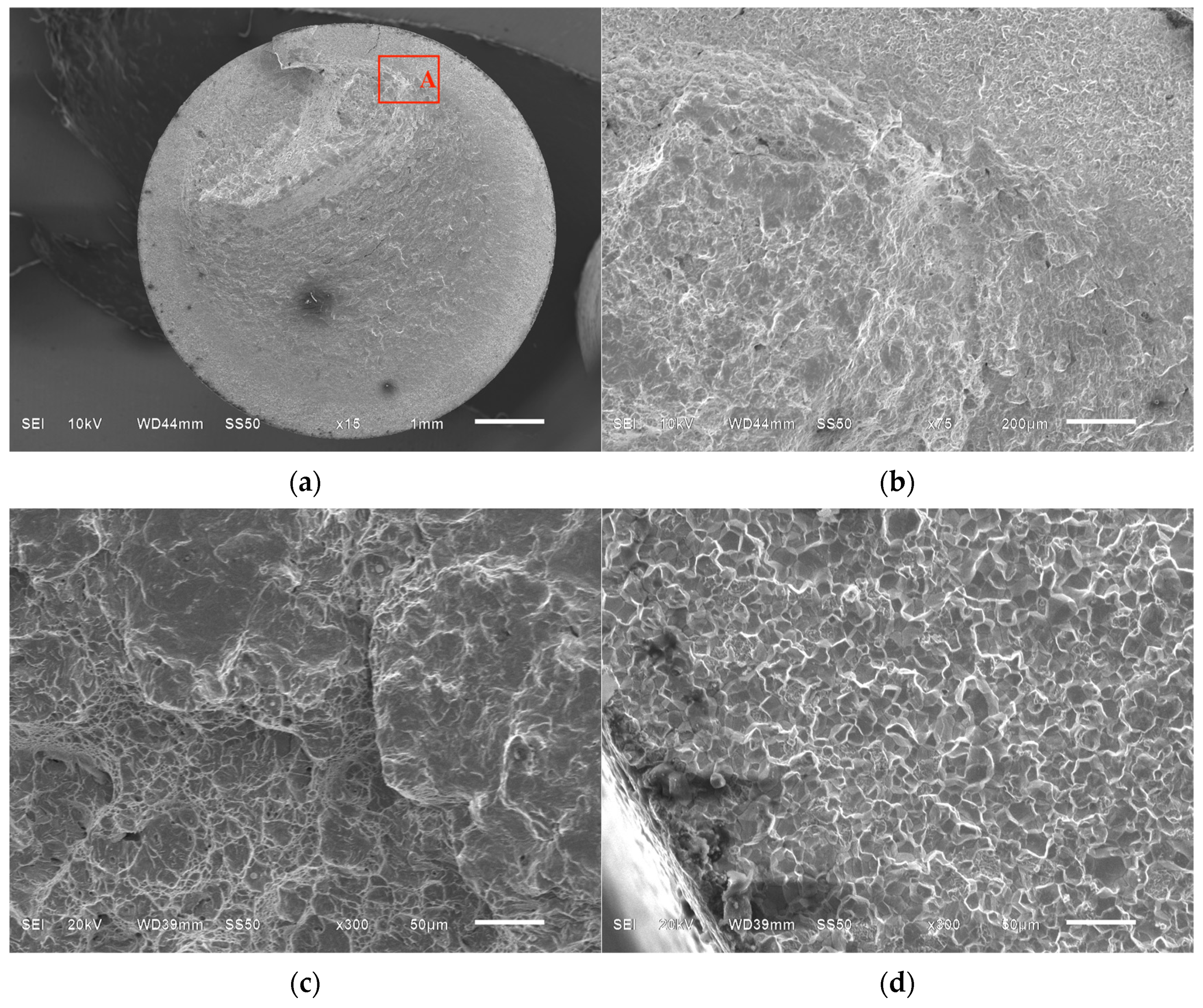
Figure 8 shows the SEM fractographs of the fracture morphologies of the case-carburized specimens in the low-cycle domain. These differ from those of the specimens in the uniform material in that for the case-carburized specimen, the fatigue nucleation initiates from inclusions or cementite in the transition zone rather than from the surface of the specimen shown in Figure 8b. Additionally, note that, as for the case-carburized material, microcracks are always more prone to propagate to the softer core material, leading to a smoother fracture surface being observed in the carburized case, as shown in Figure 8a. The transition zone is defined as the domain between the completely carburized layer and the core, at a depth between approximately 350 μm and 800 μm for the case-carburized solid specimen here. As shown in Figure 8c, in the core, significant plastic deformation has occurred, while a completely brittle fracture occurred in the carburized case in Figure 8d.
4. Conclusions
- Although the case-carburized solid specimen can be considered a combination of the carburized case and the pseudo-carburized steel, the overall mechanical behavior of the case-carburized material is much closer to that of the completely carburized materials. This means that the mechanical behavior of the carburized case dominates that of the case-carburized parts. In the low-cycle fatigue (LCF) domain, however, the fatigue performance of the case-carburized material is significantly better than that of the two types of homogeneous materials. Furthermore, the fatigue performance of the completely carburized material is slightly worse than that of the pseudo-carburized material.
- SEM fractographs were obtained from the fracture surfaces of three types of specimens. Compared with the uniform material specimens, under the stress-controlled LCF test, the fatigue nucleation in the case-carburized specimen might not initiate from the surface of the specimen but in the transition zone, and the microcracks are always more prone to propagate to the softer core material.
- The carbon content in the 18Cr2Ni4WA low-carbon steel specimens does not improve their low-cycle fatigue properties. However, the graded performance and the compressive residual stress induced by the carburization process could be the primary factors in enhancing the fatigue life of case-carburized components. For ultra-high-power gear transmission systems in the GTF engine, the evaluation of low-cycle fatigue for gears should mainly consider the influences of the carburized case on the carburized gears.
Author Contributions
Conceptualization, methodology, data curation, writing—original draft preparation, writing—review and editing, J.C. and J.Y.; project administration, funding acquisition, J.C. All authors have read and agreed to the published version of the manuscript.
Funding
This research was funded by Aerospace Power Foundation of China, grant number 6141B090323.
Institutional Review Board Statement
Not applicable.
Informed Consent Statement
Not applicable.
Data Availability Statement
Not applicable.
Conflicts of Interest
The authors declare no conflict of interest.
References
- Woods, J.L.; Daniewicz, S.R.; Nellums, R. Increasing the bending fatigue strength of carburized spur gear teeth by presetting. Int. J. Fatigue 1999, 21, 549–556. [Google Scholar] [CrossRef]
- Min, G.; Guoming, C. The Heat Treatment Technique in Gear Manufacturing of China. Heat Treat. Met. 2005, 30, 30–37. [Google Scholar]
- Stickels, C.A. Carburizing, Friction, Lubrication, and Wear Technology, ASM Handbook; ASM International: Metals Park, OH, USA, 1992; Volume 18, p. 1778. [Google Scholar]
- Bonglae, J.; Shahriar, S.; Yongbo, S.; Ali, F. Cyclic deformation and fatigue behavior of carburized automotive gear steel and predictions including multiaxial stress states. Int. J. Fatigue 2017, 100, 454–465. [Google Scholar]
- Kanchanomai, C.; Limtrakarn, W. Effect of Residual Stress on Fatigue Failure of Carburized Low- Carbon Steel. J. Mater. Eng. Perform. 2008, 17, 879–887. [Google Scholar] [CrossRef]
- Guoming, C. Review on Carburizing and Hardening Technology of Gears in China. Heat Treat Met. 2008, 33, 25–33. [Google Scholar]
- Tokaji, K.; Kohyama, K.; Akita, M. Fatigue behaviour and fracture mechanism of a 316 stainless steel hardened by carburizing. Int. J. Fatigue 2004, 26, 543–551. [Google Scholar] [CrossRef]
- Jeddi, D.; Lieurade, H.P. Effect of retained austenite on high cycle fatigue behavior of carburized 14NiCr11 steel. Procedia Eng. 2010, 2, 1927–1936. [Google Scholar] [CrossRef]
- Farfán, S.; Rubio-González, C.; Cervantes-Hernández, T.; Mesmacque, G. High cycle fatigue, low cycle fatigue and failure modes of a carburized steel. Int. J. Fatigue 2004, 26, 673–678. [Google Scholar] [CrossRef]
- Yongmin, Y.; Yazheng, L.; Leyu, Z.; Sheng, X.; Guochun, W. Carburizing law and microstructure of 23CrNi3Mo drill steel. Mater. Sci. Technol. 2013, 21, 102–108. [Google Scholar]
- Zhiyong, H.; Danièle, W.; Qingyuan, W.; Claude, B. Effect of carburizing treatment on the “fish eye” crack growth for a low alloyed chromium steel in very high cycle fatigue. Mater. Sci. Eng.-A 2013, 559, 790–797. [Google Scholar]
- Dengo, C.; Meneghetti, G.; Dabala, M. Experimental analysis of bending fatigue strength of plain and notched case-hardened gear steels. Int. J. Fatigue 2015, 80, 145–161. [Google Scholar] [CrossRef]
- Stickels, C.A. HeatTreating, ASM Handbook; ASM International: Metals Park, OH, USA, 1991; Volume 4, p. 2136. [Google Scholar]
- Nathan, A.B.; Nagaraj, K.A.; Ghatu, S.; Michael, A.K. Determination of constitutive response of plastically graded materials. Int. J. Plast. 2011, 27, 728–738. [Google Scholar]
- Choi, I.S.; Dao, M.; Suresh, S. Mechanics of indentation of plastically graded materials-I: Analysis. J. Mech. Phys. Solids 2008, 56, 157–171. [Google Scholar] [CrossRef]
- Choi, I.S.; Detor, A.J.; Schwaiger, R.; Dao, M.; Schuh, C.A.; Suresh, S. Mechanics of indentation of plastically graded materials—II: Experiments on nanocrystalline alloys with grain size gradients. J. Mech. Phys. Solids 2008, 56, 172–183. [Google Scholar] [CrossRef]
- Narasimhan, R. Analysis of indentation of pressure sensitive plastic solids using the expanding cavity model. Mech. Mater. 2004, 36, 633–645. [Google Scholar] [CrossRef]
- Loganathan, T.; Purbolaksono, J.; Inayat-Hussain, J.; Wahab, N. Effects of carburization on expected fatigue life of alloys steel shafts. Mater. Des. 2011, 32, 3544–3547. [Google Scholar]
- Nathan, A.; Ghatu, S.; Nagaraj, K.; Michael, A. A new reverse analysis to determine the constitutive response of plastically graded case hardened bearing steels. Int. J. Solids Struct. 2011, 48, 584–591. [Google Scholar]
- Junjie, Y.; Keji, P. Elastoplastic Behavior of Case-Carburized 18Cr2Ni4WA Steel by Indenter Testing. J. Aerosp. Eng. 2019, 32, 04019045. [Google Scholar]
- Dao, M.; Chollacoop, N.; Van Vliet, K.J.; Venkatesh, T.A.; Suresh, S. Computational modeling of the forward and reverse problems in instrumented sharp indentation. Acta Mater. 2001, 49, 3899–3918. [Google Scholar] [CrossRef]
- Asi, O.; Can, A.C.; Pineault, J.; Belassel, M. The relationship between case depth and bending fatigue strength of gas carburized SAE 8620 steel. Surf. Coat. Technol. 2007, 201, 5979–5987. [Google Scholar] [CrossRef]
- Zhinan, Y.; Yulong, J.; Fucheng, Z.; Ming, Z.; Nawaz, B.; Chunlei, Z. Microstructural evolution and performance change of a carburized nanostructured bainitic bearing steel during rolling contact fatigue process. Mater. Sci. Eng.-A 2018, 725, 98–107. [Google Scholar]
- Kwofie, S. An exponential stress function for predicting fatigue strength and life due to mean stresses. Int. J. Fatigue 2001, 23, 829–836. [Google Scholar] [CrossRef]
- Patricio, E.C.; Nima, S.; Steven, R.D.; Robert, D.M. Fatigue behavior of Ti-6Al-4V ELI including mean stress effects. Int. J. Fatigue 2017, 99, 87–100. [Google Scholar]
Figure 1.
(a) Solid specimen and (b) tubular specimen with 1 mm wall thickness.

Figure 2.
(a) Distributions of carbon content in the solid specimens and (b) distributions of hardness and (c) elastic modulus obtained from the nanoindentation tests in three types of specimens.
Figure 2.
(a) Distributions of carbon content in the solid specimens and (b) distributions of hardness and (c) elastic modulus obtained from the nanoindentation tests in three types of specimens.

Figure 3.
(a) Distribution of retained austenite (RA) and microstructures at different depths in the solid specimen: (b) on the surface of the solid specimen, (c) at the depth of 200 μm, and (d) at the depth of 800 μm.
Figure 3.
(a) Distribution of retained austenite (RA) and microstructures at different depths in the solid specimen: (b) on the surface of the solid specimen, (c) at the depth of 200 μm, and (d) at the depth of 800 μm.


Figure 4.
Axial residual stress distribution of case-carburized solid specimen. Bars on top indicate the standard deviation.
Figure 4.
Axial residual stress distribution of case-carburized solid specimen. Bars on top indicate the standard deviation.

Figure 5.
Stress–strain curves obtained from tensile tests of three different specimens.

Figure 6.
Reversals to failure of pseudo-carburized specimens and carburized specimens.

Figure 7.
Fracture surfaces of homogeneous materials at low-cycle domain: (a) fracture morphology of pseudo-carburized specimen at Nf = 40,929 cycles and (b) fracture morphology of carburized tubular specimen at Nf = 22,666 cycles.
Figure 7.
Fracture surfaces of homogeneous materials at low-cycle domain: (a) fracture morphology of pseudo-carburized specimen at Nf = 40,929 cycles and (b) fracture morphology of carburized tubular specimen at Nf = 22,666 cycles.

Figure 8.
Fracture surface of the case-carburized specimen at Nf = 13,367 cycles: (a) whole fracture morphology, (b) fatigue nucleation at location A, (c) fracture morphology in the core, and (d) fatigue morphology in the case.
Figure 8.
Fracture surface of the case-carburized specimen at Nf = 13,367 cycles: (a) whole fracture morphology, (b) fatigue nucleation at location A, (c) fracture morphology in the core, and (d) fatigue morphology in the case.


Table 1.
Tensile properties of the materials.
| Type - | E GPa | MPa | Fracture Stress MPa | Fracture Strain % |
|---|---|---|---|---|
| C.Tub. | 197.0 | 1102.0 | 1262.0 | 0.93 |
| C.Cylin. | 197.0 | 1059.0 | 1313.0 | 1.13 |
| P.Cylin. | 197.0 | 674.0 | 973.0 | 5.03 |
Table 2.
Material parameters in the Basquin model.
| Type - | A MPa | n - | MPa | - |
|---|---|---|---|---|
| C.Tub. | 2113.8 | −0.1666 | 310.7 | 0.9149 |
| C.Cylin. | 2649.5 | −0.1396 | 531.2 | 0.8967 |
| P.Cylin. | 2715.3 | −0.1829 | 330.4 | 0.9524 |
Table 3.
Parameters of the Kwofie model for the case-carburized material.
| Type - | MPa | MPa | - | - |
|---|---|---|---|---|
| Based on C.Tub. | 492.9 | 1262.0 | 1.3980 | 0.8501 |
| Based on P.Cylin. | 449.5 | 973.0 | 0.9996 | 0.8006 |
Disclaimer/Publisher’s Note: The statements, opinions and data contained in all publications are solely those of the individual author(s) and contributor(s) and not of MDPI and/or the editor(s). MDPI and/or the editor(s) disclaim responsibility for any injury to people or property resulting from any ideas, methods, instructions or products referred to in the content. |
© 2023 by the authors. Licensee MDPI, Basel, Switzerland. This article is an open access article distributed under the terms and conditions of the Creative Commons Attribution (CC BY) license (https://creativecommons.org/licenses/by/4.0/).
Share and Cite
MDPI and ACS Style
Cao, J.; Yang, J. Mechanical Behavior and Low-Cycle Fatigue Performance of a Carburized Steel for GTF Engines. Processes 2023, 11, 1275. https://doi.org/10.3390/pr11041275
AMA Style
Cao J, Yang J. Mechanical Behavior and Low-Cycle Fatigue Performance of a Carburized Steel for GTF Engines. Processes. 2023; 11(4):1275. https://doi.org/10.3390/pr11041275
Chicago/Turabian StyleCao, Juan, and Junjie Yang. 2023. "Mechanical Behavior and Low-Cycle Fatigue Performance of a Carburized Steel for GTF Engines" Processes 11, no. 4: 1275. https://doi.org/10.3390/pr11041275
Note that from the first issue of 2016, this journal uses article numbers instead of page numbers. See further details here.