Article

Experimental Study on Mechanical Properties of Automatic Anchoring Preloaded Energy Absorbing Anchor Rods

1
School of Mechanics and Engineering, Liaoning Technical University, Fuxin 123000, China
2
International Engineering Company of CCTEG, Beijing 100029, China
*
Author to whom correspondence should be addressed.
Processes 2023, 11(4), 1130; https://doi.org/10.3390/pr11041130
Submission received: 21 March 2023 / Revised: 2 April 2023 / Accepted: 5 April 2023 / Published: 6 April 2023
(This article belongs to the Topic Energy Storage Using Underground Mine Space)

Abstract

:
In order to enhance the anti-impact mechanical properties of the roadway support system, an automatic anchoring pre-tightening energy absorbing anchor composed of rod body, tray, constant resistance energy absorber, energy-absorbing casing bulging block, pre-tightening force warning washer, and nut and anchorage force warning stopper was designed and developed for the special requirements of rock burst roadway support. The anchor can automatically judge the anchoring force and pre-tightening force of the anchor, and also has the functions of energy absorption and early warning. The static load tensile test and impact test are used to study the mechanical properties of the energy absorbing anchor, such as the displacement distance, energy absorption, and impact time, and they are then compared with the mechanical properties of the conventional anchor. It is concluded that under static load, the yielding distance of the energy absorbing anchor is 1.67 times that of conventional anchor. The absorbed energy is 1.61 times that of the conventional anchor. Under the impact load, the displacement distance of the energy absorbing anchor is 2.02 times that of the conventional anchor. The absorbed energy is 1.85 times that of the conventional anchor, and the anti-impact time is 1.47 times that of the conventional anchor. The energy absorbing anchor increases the constant resistance deformation stage of the energy absorber during the deformation process, so that the anchor has better deformation ability, energy absorption, and anti-impact ability than the conventional anchor, and it can thus effectively guide and control the release and transformation of surrounding rock deformation energy.

1. Introduction

Surrounding rock control of a deep roadway is one of the theoretical bottlenecks and key problems in deep mining. Among these problems, the coordination between support and roadway surrounding rock is the core problem of deformation control of deep roadway surrounding rock.
Anchor support is a kind of reinforcement support often used in roadway support, which is to change the mechanical state of the surrounding rock itself through the anchor inside the surrounding rock, and then use the anchor and the surrounding rock to work together to maintain the stability of the roadway. The behavior mechanism, application, and mode of bolts have evolved into standard practices for all types of underground excavation, significantly improving the overall rock mass properties [1]. In recent years, it has been proved that the use of energy absorbing anti-impact support can effectively control the deformation of the surrounding rock of the roadway and can effectively prevent the impact ground pressure of the roadway [2,3].
Scholars at home and abroad have conducted a lot of research on anchor rods and have obtained research results. Krzysztof [4] designed and tested anchor load cells, the effectiveness of which has been experimentally confirmed for anchor support. Małkowski [5] studied three roadways in hard coal mines under different support schemes to verify the correctness of roadway support selection under specific mining and geological conditions. Matayev [6] determined the efficiency and prospects for the use of combined anchor and shotcrete support, which improves the reliability of mine operations and miners’ labor productivity while ensuring a reduction in its material consumption and costs. Skrzypkowski [7] used indoor tests to determine quasi-static coefficients and to determine load-displacement characteristics of partially buried anchors, and on this basis, stress-strain characteristics were analyzed. Knox [8] pointed out that deep and highly stressed mines are susceptible to mining-induced seismic activity and that energy-absorbing anchors can withstand large loads and accommodate large deformations. Impact tests were used to determine the maximum displacement and dissipation energy of energy-absorbing anchors before fracture. Kang [9] studied the mechanical properties of various components of anchor rods, including rod body, threaded section, butt plate, spherical washer, and friction reducing washer. Wu [10] analyzed the impact resistance of different toughness anchor rods from the micro-fine viewpoint. Dong [11] designed an energy absorbing anti-impact anchor support member mainly by using the energy absorbing property of axial tearing and the curling deformation of metal round tubes. Ning [12] proposed a method to reduce anchor rod breakage by improving the stress state of the anchor rod, changing the anchor rod anchoring method, and optimizing the shape of the rod, and he designed a rebar anchor rod with a new shape structure. He [13] independently developed constant resistance large deformation anchor rods adapted to the surrounding rock support of soft rock roadways and deep roadways. Wang [14] studied the mechanical properties and engineering applications of constant resistance energy absorbing anchor rods with good impact resistance and overall deformation capacity. Fu [15] concluded that the reasonable arrangement of anchor rod (cable) support parameters can improve its working interval of synergistic impact prevention and reduce the damage of impact ground pressure on the surrounding rock of the roadway. Wang [16,17,18,19,20] designed different anchors based on the principle of energy absorption by structural deformation and studied their static and dynamic mechanical properties with good energy absorption and impact prevention.
The results of existing studies show that adding energy absorbing devices with energy absorbing characteristics to the anchor rod design can effectively absorb the impact energy of the surrounding rock and enhance the mechanical properties of the anchor rod against impact. However, the existing energy absorbing anchor rods are costly, the constant resistance performance needs to be improved, the judgment of anchorage force and preload force during construction is time-consuming and laborious, and the downhole workers are not clear about the force status of the anchor rods (no warning function). To solve this problem, an automatic anchor preload energy absorbing anchor rod (referred to as an energy absorbing anchor rod) is designed and developed, and the mechanical characteristics of the energy absorbing anchor rod are studied by static load tensile test and impact test and then compared with those of a conventional anchor rod.

2. Energy Absorbing Anchor Design

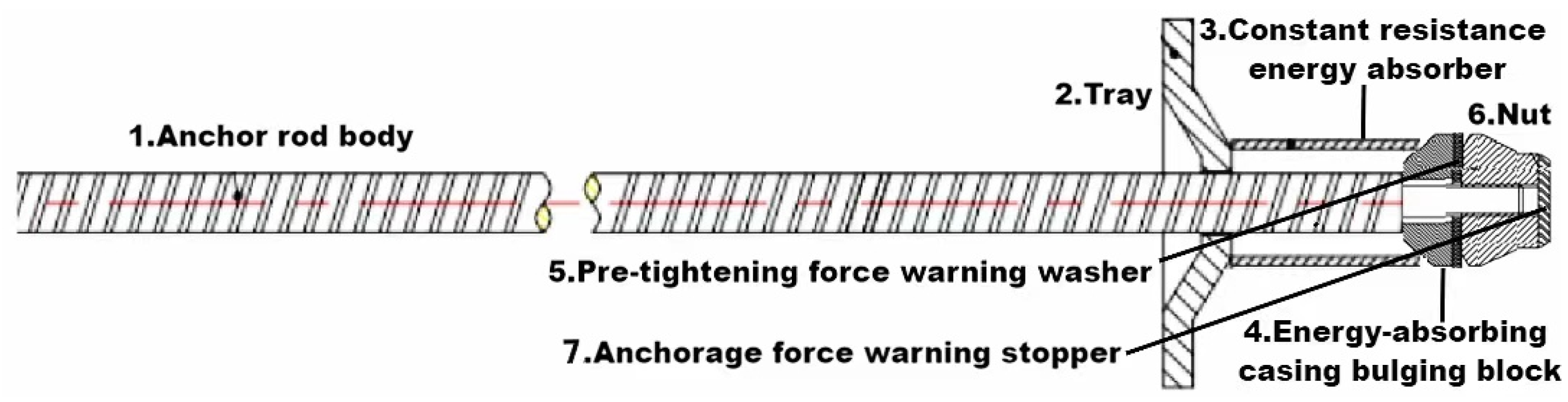
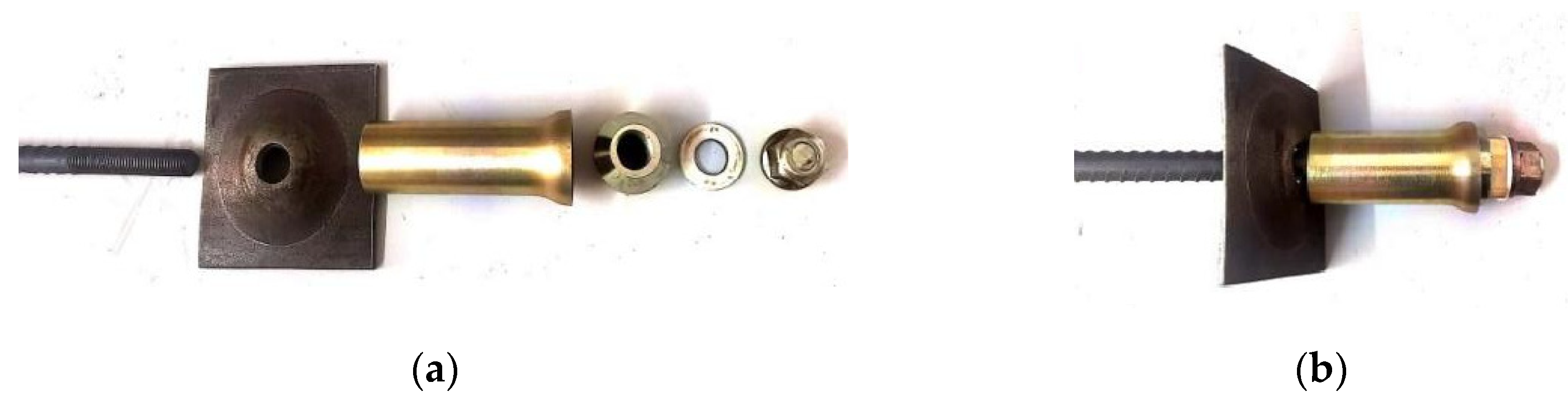
2.1. Energy Absorbing Anchor Structure

In order to enhance the anti-impact mechanical properties of the roadway support system, an automatic anchoring pre-tightening energy absorbing anchor composed of rod body, tray, constant resistance energy absorber, energy-absorbing casing bulging block, pre-tightening force warning washer, and nut and anchorage force warning stopper has been innovatively designed and developed for the special requirements of rock burst roadway support. The schematic diagram of energy absorbing anchor construction is shown in Figure 1. The energy absorbing anchor rod body, tray, constant resistance energy absorber, energy-absorbing casing bulging block, and nut and anchorage force warning stopper are all made of metal, and the pre-tightening force warning washer is made of resin. The tray provides support and spreads the load between the anchor rod and the coal (rock) body to prevent the anchor rod from failing due to excessive load. The nut compresses the pallet to apply pre-stress to the anchor rod, the deformation of the surrounding rock is transferred to the rod body through the pallet and nut, the working resistance of the rod body increases to control the deformation of the surrounding rock, and the energy-absorbing casing bulging block plays the role of adjusting the energy-absorbing resistance after expanding and deforming.
The right outer surface of the energy absorbing anchor rod is provided with an external thread, the nut is screwed to the right end of the rod through the external thread, and the anchorage force warning stopper is fixed on the axial right end of the nut. The pre-tightening force warning washer, the energy-absorbing casing bulging block, the constant resistance energy absorber [21], and the tray are set on the rod body in order, as shown in Figure 2. The constant resistance energy absorber is a thin-walled round tube structure, the right end of the constant resistance energy absorber has a flared mouth structure, the constant resistance energy absorber is coated with reflective paint, and the bearing capacity of the constant resistance energy absorber is designed to be 95–100% of the yield force of the rod. The left side of the energy-absorbing casing bulging block is a conical structure, the right side is a cylindrical structure, the right end is a flat structure, and the center is to the left of the rod penetration hole. The conical structure of the energy-absorbing casing bulging block is in contact with the flared structure of the constant resistance energy absorber.
During the installation process, the drilling rod is first used to make a hole in the coal (rock) body, and then the energy-absorbing anchor rod is screwed into the hole by relying on a certain torque. This fundamentally improves the strength and safety of the support structure; enhances the efficiency and quality of the anchor installation process; makes the monitoring of pre-stress and anchorage force more convenient, accurate, and systematic; greatly improves the efficiency of coal mine employees; reduces the waste of human and material resources; and ensures that the deep shaft anchor support solution has higher economic practicality and technical feasibility.

2.2. Functional Characteristics of Energy Absorbing Anchor

2.2.1. Automatic Determination of Anchorage Force

Anchor anchoring force is the ability of the anchor rod to consolidate the surrounding rock by resin anchorant, and it is an important indication of the working effectiveness of the anchor rod. In advance, according to the anchor force value to be achieved by the anchor rod, the force of the designed rod breaking through the anchorage force warning stopper is the anchor force value. In the process of anchor installation, when the nut is screwed into the rod for the first time, the nut should be screwed until the rod rests on the anchor force warning stop, then screw the nut should continue to be screwed. If the rod does not break through the anchor force warning stop and rotate with the nut, it means the anchor force of the rod does not reach the design requirement; if the rod can break through the anchor force warning stop so that the nut can continue to screw in the rod, it means the anchor force of the rod reaches the design requirement. The anchoring force of the rod has reached the design requirement. The anchorage force is automatically determined by observing the state of the anchorage force warning stopper of the energy absorbing anchor.

2.2.2. Automatic Determination of Preload Force

Anchor preload is the axial tension force exerted on the anchor rod during its installation. In advance, according to the anchor rod’s need to achieve the value of preload force, the design preload force warning washer is squeezed with broken force for the anchor preload force value. In the process of tightening the nut, when the pre-tightening force warning washer clamped between the energy-absorbing casing bulging block and the nut is squeezed and broken, it means that the preload force exerted by the nut on the rod reaches the design requirements, otherwise it does not reach the design requirements. By observing the breakage of the pre-tightening force warning washer, the preload force can be automatically judged.

2.2.3. Early Warning Function and Logo

The outer surface of the tube body of the constant resistance energy absorber is coated with reflective paint. When the expansion and deformation of the constant resistance energy absorber occurs, the color of the reflective paint warning mark disappears, indicating that the rod has entered the yielding stage. By observing whether the color of the reflective paint mark on the outer surface of the tube body disappears, the purpose of the warning effect is achieved.

2.3. Anti-Impact Mechanism of Energy Absorbing Anchor and Applicability Analysis

After the installation of the energy absorbing anchor under the impact load of the surrounding rock, when the impact load is less than the energy absorber bearing capacity, when the energy absorber is not deformed, and when the rod is in the elastic stage, the bearing capacity rises linearly. When the impact load reaches the threshold value of the energy absorber deformation load, the energy absorber constant resistance deformation is damaged, and in the process of deformation damage to absorb the impact energy, the bearing capacity is in the constant stage. After the end of the energy absorber deformation, if the impact load is still greater than the threshold value of the energy absorber deformation load, the rod becomes the main body of the load, subjected to the tension of the yielding stage, and the bearing capacity has a small increase and remains constant. If the yielding stage of the rod is over, the impact load continues to increase, the rod enters the strengthening stage, and the bearing capacity continues to rise until the rod is pulled off and the anchor fails.
Energy absorbing anchor rods are suitable for most of the impact ground pressure roadways, and the actual field shows that the stress concentration area of the mine is not only subject to high static load but is also subject to frequent impact load. Energy-absorbing anchors are implanted into the coal rock around the roadway to maintain the integrity of the surrounding rock, improve the stress distribution in the roadway, and increase the ability of the surrounding rock to resist dynamic load impact. The test results show that the energy-absorbing anchor rod exhibits significant plastic deformation characteristics, whether it is loaded statically or by impact loading, and the anchor rod and the surrounding rock form a reduced propensity to impact, while the support resistance provided by the energy-absorbing anchor rod can increase the critical load of the impact ground pressure occurring in the roadway. The energy absorbing anchor has a special structure of a constant resistance energy absorber and an energy-absorbing casing bulging block. Under the action of impact load or static load, when the constant resistance energy absorber is squeezed by the energy-absorbing casing expander and deformation occurs, the constant resistance energy absorber directly absorbs the energy released during the deformation of the surrounding rock through its own plastic deformation and indirectly absorbs the energy released during the deformation of the surrounding rock by giving way to space. It can realize the self-balancing of the surrounding rock stress and improve the stability of the “energy absorbing anchor—roadway surrounding rock” support system.

3. Analysis of Mechanical Properties of Anchor under Static Load

3.1. Basic Parameters of Specimen

3.1.1. Basic Parameters of Conventional Anchor Specimen

In order to study the mechanical properties of conventional anchor rods, the tests are conducted using Q235 steel processed conventional anchor rods for quasi-static tensile tests. The length of conventional anchor rods is 2 m, the diameter is 22 mm, the front and rear ends have 300 mm threads for anchoring, and the wall thickness of the anchor tray is 8 mm. The basic parameters of the conventional anchor rods are shown in Table 1.

3.1.2. Basic Parameters of Energy Absorbing Anchor Specimen

In order to study the mechanical properties of energy absorbing anchor rods, a Q235 steel energy absorbing anchor rod is used for quasi-static tensile testing. The length of the energy absorbing anchor rod is 2 m, the diameter is 22 mm, the front and rear ends have 300 mm threads for anchoring, and the wall thickness of the anchor tray is 8 mm. The length of the constant resistance energy absorber is 150 mm, with a 41 mm inner wall diameter and a 3 mm wall thickness. The cone angle of the left side of the energy-absorbing casing bulging block is 53.6°, and it has a 15 mm height and a 50 mm diameter of the right side of the cylindrical structure. The basic parameters are shown in Table 2, and the energy absorbing anchor is shown in Figure 3.

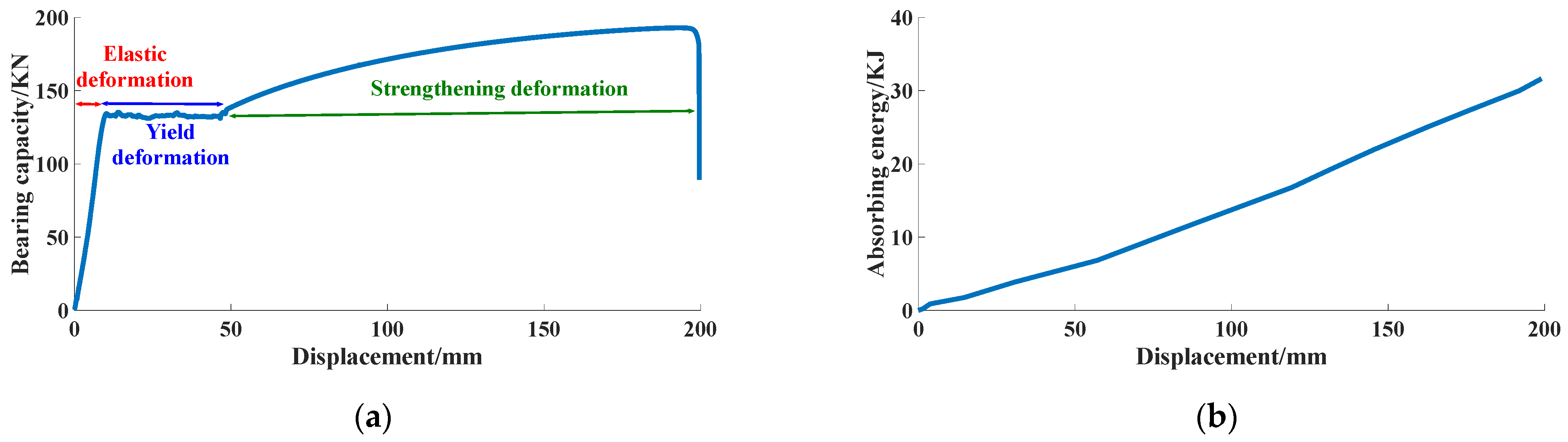
3.2. Study on Static Load Test of Conventional Anchor

The test was conducted by a microcomputer-controlled electrical tensile testing machine for quasi-static tensile testing of anchor rods, and the test rig included a loading system, a load control system, and a monitoring display system. The model of the tester is LAW-600 with a capacity of 600 KN, power of 5 KW, and a tensile rate setting of 50 mm/min. The test setup is as shown in Figure 4. Regarding anchor rod static load test system usage, after the hydraulic system motor starts running, it drives the oil pump to start. The high pressure oil then enters the working cylinder, the working piston is pushed and makes the cross beam move, and the cross beam drives the front chuck to move through the tie bar. When the beam is ejected, the distance between the front collet and the rear collet increases, and the tensile test is conducted. During the tensile test, the sensor can transmit the pressure and displacement changes as signals to the microcomputer system. Through the collection of pressure and displacement by the microcomputer system, the computer screen shows the curve of the specimen tensile test parameters, and the experimental data can be post-processed at the same time.
The test force and the displacement data are obtained from the anchor rod test system, and the energy absorbed by the anchor rod is obtained by integrating the force-displacement curve. The static force-displacement curve of the anchor rod is measured by the static load tensile test, so that the energy absorbed by the anchor rod under static load is obtained. The bearing capacity-displacement curve and energy absorption characteristic curve of conventional anchors are shown in Figure 5.
From Figure 5, it can be seen that (1) during the tensile process, the conventional anchor rod is mainly wired in three stages of elastic deformation, yield deformation, and strengthening deformation (the anchor rod breaks instantly after reaching tensile strength). The displacement of elastic deformation, yield deformation, and strengthening deformation are 10.17 mm, 46.61 mm, and 140.39 mm, accounting for 5.2%, 23.6%, and 71.2% of the total displacement, respectively. (2) The energy absorbed in the elastic deformation stage, yield deformation stage, and strengthening deformation stage of the conventional anchor is 0.72 kJ, 4.93 kJ and 26.34 kJ, accounting for 2.3%, 15.4% and 82.3% of the total energy absorbed, respectively.

3.3. Study on Static Load Test of Energy Absorbing Anchor Anchor

The energy absorbing anchor static load tensile test is shown in Figure 6, and the constant resistance energy absorber before and after the test is shown in Figure 7.
The comparison of the mechanical property curves of the conventional anchor and the energy absorbing anchor under static load is shown in Figure 8, and the comparison of the mechanical properties of the conventional anchor and the energy absorbing anchor during loading is shown in Table 3.
From Figure 8 and Table 3, it can be deduced that (1) in the tensile process, the energy absorbing anchor is mainly wired with four stages: elastic deformation, constant resistance absorber yield deformation, yield deformation, and strengthening deformation. Compared with the conventional anchor, the energy absorbing anchor increases the deformation stage of the constant resistance energy absorber. (2) In the tensile process, the displacements of the elastic deformation stage, constant resistance absorber yielding deformation stage, yielding deformation stage, and strengthening deformation stage of the energy absorbing anchor are 43.33 mm, 130.93 mm, 26.23 mm, and 129.09 mm, accounting for 13.1%, 39.7%, 8%, and 39.2% of the total displacements, respectively. The yield distances of conventional anchors and energy absorbing anchors are 197.17 mm and 329.58 mm, respectively, the difference between them is 132.41 mm, and the yield distance of the energy absorbing anchors is 1.67 times of that of conventional anchors. (3) In the tensile process, the energy absorbed in the elastic deformation phase, the yield deformation phase, the yield deformation phase, and the reinforcement deformation phase of the energy absorbing anchor are 4.03 kJ, 19.63 kJ, 3.69 kJ, and 24.27 kJ, accounting for 7.8%, 38%, 7.2%, and 47% of the total absorbed energy, respectively. The absorbed energy of the conventional anchor rod and energy absorbing anchor rod are 31.99 kJ and 51.62 kJ, respectively, and while the difference between them is 19.63 kJ, the absorbed energy of energy absorbing anchor rod is 1.61 times of the absorbed energy of conventional anchor rod. (4) In the tensile process, the damaged loads of conventional anchor rod and energy absorbing anchor rod are 192.14 kN and 193.40 kN, respectively, which indicates that the difference in bearing capacity between conventional anchor rod and energy absorbing anchor rod under static load is small. (5) In the tensile process, the energy absorption anchor is divided into two parts: one is the expansion energy absorption of constant resistance energy absorber, and the other is the energy absorption of the anchor rod itself under tension. The constant resistance energy absorber has good constant resistance performance in the process of compression, and also has a more stable deformation damage mode.

4. Analysis of Mechanical Properties of Anchor under Impact Load

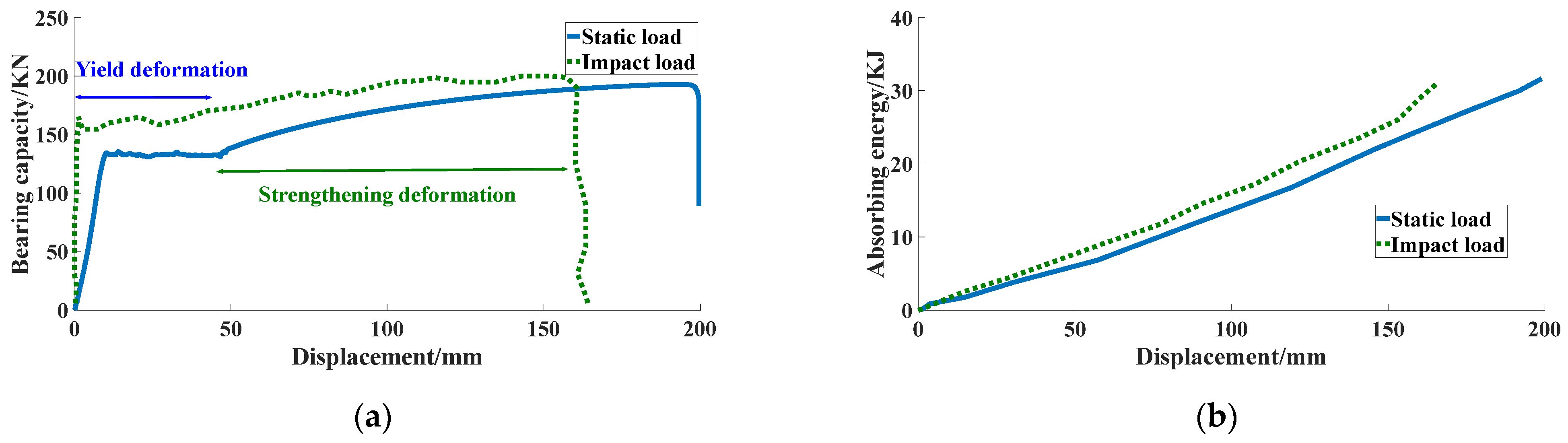
4.1. Study on Impact Load Test of Conventional Anchor

The test was conducted using a 300 KN anchor impact test rig for conventional anchor rods. The test rig consisted of a clamping system, a loading system, a load control system, and a monitoring display system, and the impact loading is set to 24 tons, with the test setup as shown in Figure 9. Regarding the anchor rod impact load test system usage, the control pump in the anchor rod impact test platform should be turned on, the pressure value in the “static pressure setting value” for static pressure loading should be entered, the “hydraulic cylinder forward” button should be used to adjust the hydraulic cylinder position and change the “static pressure setting value”, and the high pressure pump should be turned on, the given pressure in the “dynamic pressure setting value” for dynamic pressure loading should be entered, and the accumulator will then be pressurized and enter the impact phase. Regarding the “static pressure setting value”, the high pressure pump should be turned on, the given pressure in the “dynamic pressure setting value” to load the dynamic pressure should be entered, and then the accumulator is pressurized and enters the impact stage. After that, start collecting—return valve open—impact valve open, wait for 3–5 s after impact, close each button in turn, reset the hydraulic cylinder, give 0 to “static pressure set value”, and turn off the control pump. Finally, open the history curve, and select the file you need to read, while the experimental data can be found post-processing operations.
The dynamic force-displacement curve of the anchor rod is measured by the impact load loading test, and the energy absorbed by the anchor rod is obtained by integrating the force-displacement curve. A comparison of the mechanical property curves of conventional anchor rods under static load and impact load is shown in Figure 10, and a comparison of the mechanical properties of conventional anchor rods is shown in Table 4.
From Figure 10 and Table 4, it can be deduced that (1) during the action of the impact load, the linear elastic deformation phase of the conventional anchor rod is not obvious due to the instantaneous action of the impact load on the anchor rod body, and there are mainly two phases—yield deformation and strengthening deformation. The displacement of the yield deformation phase and the strengthening deformation phase are 48.76 mm and 117.2 mm, accounting for 29.4% and 70.6% of the total displacement, respectively. (2) During the impact load, the energy absorbed in the yield deformation and strengthening deformation stages of the conventional anchor is 7.07 kJ and 23.36 kJ, accounting for 24.8% and 75.2% of the total energy absorbed, respectively. (3) The yield distances of conventional anchor rods under static load and impact load are 197.17 mm and 165.96 mm, respectively, with a difference of 31.21 mm, indicating that the elongation of conventional anchor rods under impact load is lower than that of conventional anchor rods under static load. (4) The energy absorbed by conventional anchor rods under static load and impact load is 31.99 kJ and 31.08 kJ, respectively, with a difference of 0.91 kJ, indicating that the difference between the energy absorbed by conventional anchor rods under impact load and that under static load is small. (5) The damage loads of conventional anchor rods under static load and impact load are 192.14 kN and 203.49 kN, respectively, with a difference of 11.35 kN, indicating that the bearing capacity of conventional anchor rods under impact load is higher than that of conventional anchor rods under static load.

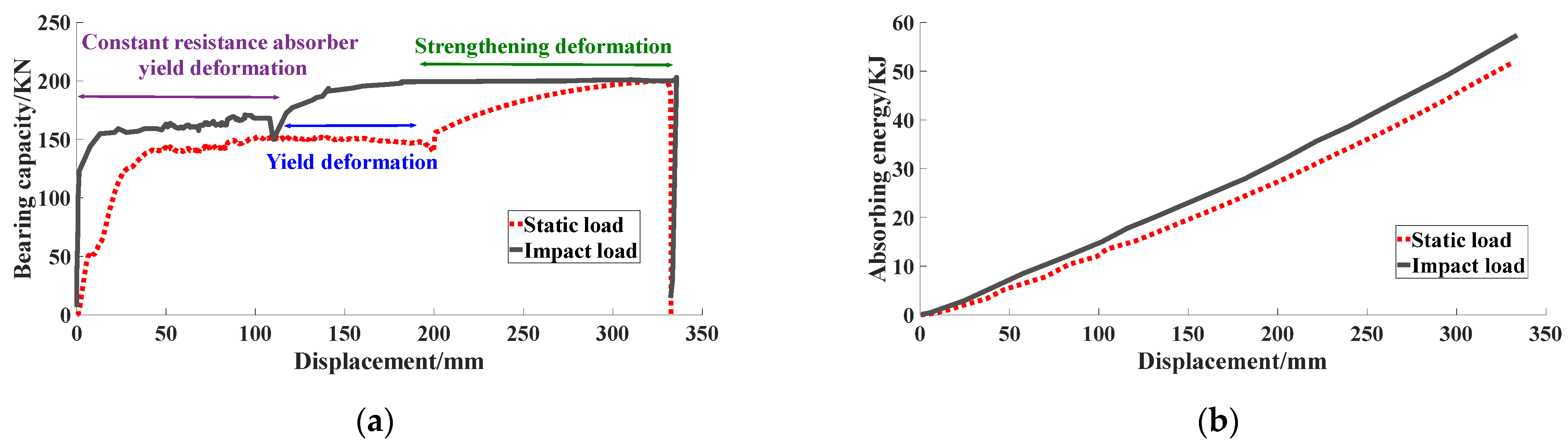
4.2. Study on Impact Load Test of Energy Absorbing Anchor

A comparison of the mechanical property curves of energy absorbing anchor rods under static load and impact load is shown in Figure 11, and a comparison of the mechanical properties of energy absorbing anchor rods is shown in Table 5.
From Figure 11 and Table 5, it can be deduced that (1) in the process of impact load, the energy absorbing anchor mainly has three stages—the constant-resistance energy-absorbing device giving way to deformation, yield deformation, and strengthening deformation. The displacements of the constant-resistance energy absorbing anchor in yield deformation, yield deformation, and strengthening deformation are 121.47 mm, 63.21 mm, and 150.69 mm, respectively, accounting for 36.3%, 18.8%, and 44.9% of the total displacements, respectively. (2) In the process of the impact load, the energy absorption anchor rod absorbs 20.65 kJ, 10.01 kJ, and 26.97 kJ in the yield deformation stage, yield deformation stage, and strengthening deformation stage of the constant resistance energy absorber, accounting for 35.8%, 17.4%, and 46.8% of the total energy absorption, respectively. (3) The yield distances of energy absorbing anchor rods under static load and impact load are 329.58 mm and 335.37 mm, respectively, with a difference of 5.79 mm, indicating that the elongation of energy absorbing anchor rods under impact load is higher than that of energy absorbing anchor rods under static load. (4) The energy absorbed by energy absorbing anchor rods under static load and impact load are 51.62 kJ and 57.63 kJ, respectively, with a difference of 6.01 kJ between them, indicating that the energy absorbed by energy absorbing anchor rods under impact load is better than that under static load. (5) The damage loads of energy absorbing anchor rods under static load and impact load are 194.40 kN and 203.31 kN, respectively, with a difference of 9.91 kN between them, indicating that the load-bearing capacity of energy absorbing anchor rods under impact load is higher than that of energy absorbing anchor rods under static load.

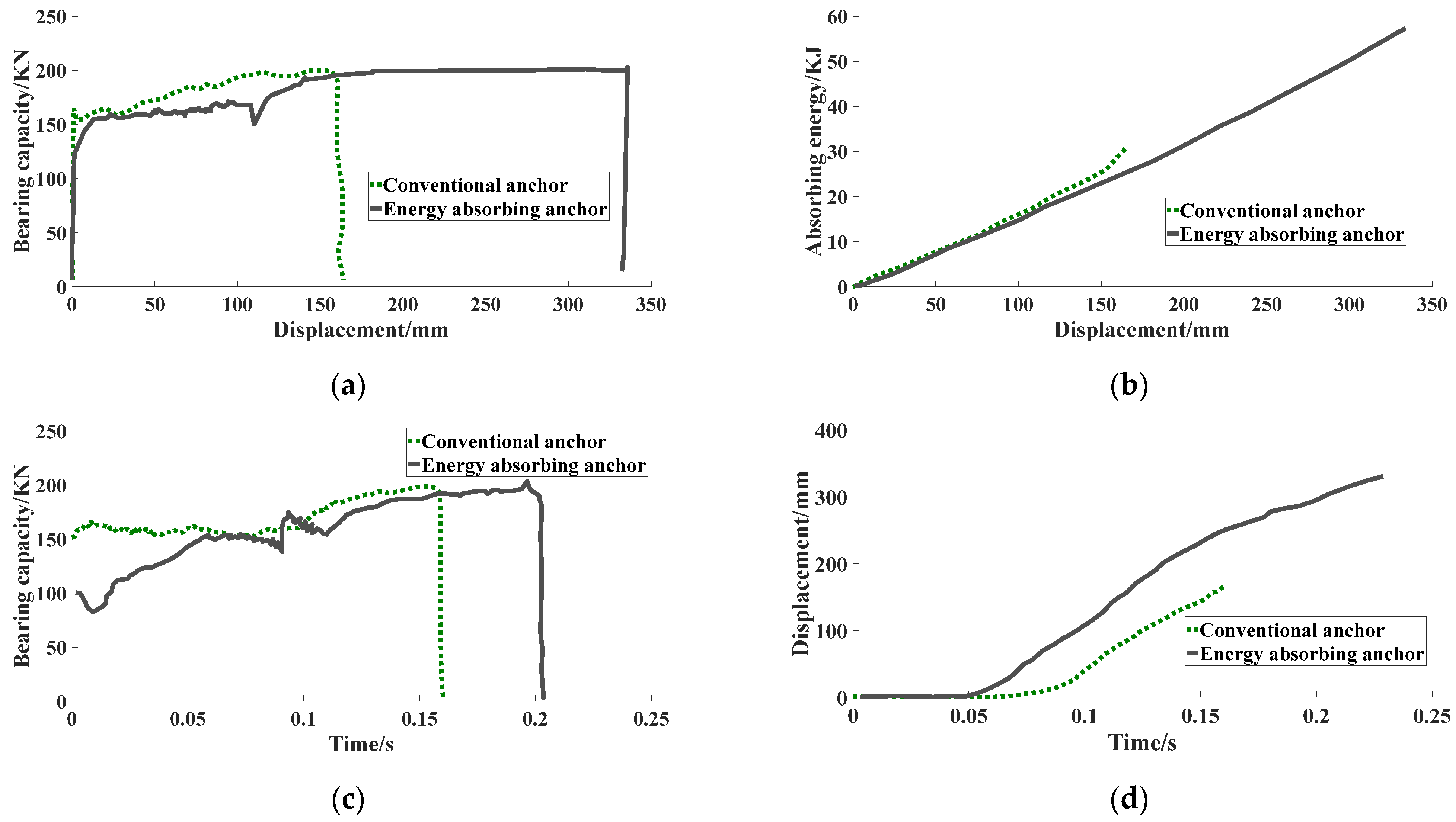
4.3. Comparison of Mechanical Properties of Conventional Anchor and Energy Absorbing Anchor in Impact Load Tests

A comparison of the mechanical property curves of conventional and energy absorbing anchor rods under impact loading is shown in Figure 12, and a comparison of the mechanical properties of conventional and energy absorbing anchor rods is shown in Table 6.
From Figure 12 and Table 6, it can be seen that (1) the yield distances of the conventional anchor rod and the energy absorbing anchor rod during impact action are 165.96 mm and 335.37 mm, respectively, the difference between them is 169.41 mm, and the yield distance of energy absorbing anchor rod is 2.02 times that of the conventional anchor rod. This indicates that the elongation of energy absorbing anchor rods under impact load is higher than that of conventional anchor rods under impact load. (2) The energy absorbed by the conventional anchor rod and the energy absorbing anchor rod during impact load action is 31.08 kJ and 57.63 kJ, respectively, and the difference between them is 26.55 kJ. The energy absorbed by the energy absorbing anchor rod is 1.85 times that of the energy absorbed by the conventional anchor rod. This means that the energy absorbed by the energy absorbing anchor rod under the impact load is better than that of the conventional anchor rod under the impact load. (3) During the impact load, the impact time of energy absorbing anchor is 0.22 s, and the impact time of the conventional anchor is 0.15 s, with a difference of 0.07 s, and the impact time of the energy absorbing anchor is 1.47 times that of the conventional anchor. This means that the impact resistance of energy the absorbing anchor rod under impact load is better than that of the conventional anchor rod under impact load. (4) During the impact load, the breaking loads of conventional anchor rods and energy absorbing anchor rods under impact are 203.49 kN and 203.31 kN, respectively, indicating that the difference in bearing capacity between conventional anchor rods and energy absorbing anchor rods under impact is small. (5) During the impact load, the yield distance, impact resistance time, and absorbed energy of energy absorbing anchor rods far exceed those of conventional anchor rods, and energy absorbing anchor rods have better deformation capacity and energy-absorbing and impact prevention capacity.

5. Conclusions

We designed and developed an automatic anchor preload energy absorbing anchor consisting of anchor rod body, tray, constant resistance energy absorber, energy-absorbing casing bulging block, pre-tightening force warning washer, and nut and anchorage force warning stopper. It has the functions of automatic determination of the anchoring force, automatic determination of the preload force, and early warning.
The elongation of the conventional anchor rod under impact load is lower than that of the conventional anchor rod under static load; the difference between the energy absorbed by the conventional anchor rod under impact load and that under static load is smaller; and the bearing capacity of the conventional anchor rod under impact load is higher than that of the conventional anchor rod under static load.
The elongation of the energy absorbing anchor under impact load is lower than that of the energy absorbing anchor under static load; the energy absorbing anchor absorbs more energy under impact load than under static load; and the load carrying capacity of the energy absorbing anchor under impact load is higher than that of the energy absorbing anchor under static load.
Compared with the conventional anchor, the energy absorbing anchor adds the deformation stage of constant resistance energy absorber in the deformation process. Under static load, the yielding distance of the energy absorbing anchor is 1.67 times that of the conventional anchor, and the energy absorbing anchor absorbs 1.61 times of the energy absorbed by the conventional anchor. Under impact load, the energy absorbing anchor gave way to 2.02 times the distance of conventional anchor; the energy absorbing anchor absorbed 1.85 times the energy of conventional anchor; and the impact resistance time of the energy absorbing anchor is 1.47 times the impact resistance time of the conventional anchor.

Author Contributions

Conceptualization, Z.T. and W.Z.; methodology, Z.T.; software, Z.T. and W.Z.; validation, X.C. and D.C.; investigation, X.C.; resources, Z.T.; data curation, W.Z.; writing—original draft preparation, W.Z.; writing—review and editing, D.C. and C.W.; visualization, C.W.; supervision, Z.T.; project administration, Z.T.; funding acquisition, Z.T. All authors have read and agreed to the published version of the manuscript.

Funding

This research was funded by the National Key R&D Program for the 14th Five-Year Plan (2022YFC3004605), National-level Student Innovation Training Program (S202210147011) and the National Natural Science Foundation of China (51804152).

Data Availability Statement

Data sharing not applicable.

Acknowledgments

The authors would like to express their sincere gratitude to Discipline Innovation Team of Liaoning Technical University in this study.

Conflicts of Interest

The authors declare no conflict of interest.

References

  1. Aldrian, W.; Wyink, U.; Herrmann, C. Bolting with pumpable reactive resins—More than fixation of steel dowels in rock. Geomech. Tunn. 2019, 12, 168–174. [Google Scholar] [CrossRef]
  2. Pan, Y.S.; Xiao, Y.H.; Li, G.Z. Research and application of anti–scour hydraulic support in roadway. J. China Coal Soc. 2020, 45, 90–99. [Google Scholar] [CrossRef]
  3. Pan, Y.S.; Qi, Q.X.; Wang, A.W. Three–level support theory and technology of coal mine rock burst roadway. J. China Coal Soc. 2020, 45, 1585–1594. [Google Scholar] [CrossRef]
  4. Skrzypkowski, K. Case Studies of Rock Bolt Support Loads and Rock Mass Monitoring for the Room and Pillar Method in the Legnica–Głogów Copper District in Poland. Energies 2020, 13, 2998. [Google Scholar] [CrossRef]
  5. Małkowski, P.; Niedbalski, Z.; Majcherczyk, T. Underground monitoring as the best way of roadways support design validation in a long time period. Min. Miner. Depos. 2020, 14, 1–14. [Google Scholar] [CrossRef]
  6. Matayev, A.; Abdiev, A.; Kydrashov, A. Research into technology of fastening the mine workings in the conditions of unstable masses. Min. Miner. Depos. 2021, 15, 78–86. [Google Scholar] [CrossRef]
  7. Skrzypkowski, K. An Experimental Investigation into the Stress–Strain Characteristic under Static and Quasi–Static Loading for Partially Embedded Rock Bolts. Energies 2021, 14, 1483. [Google Scholar] [CrossRef]
  8. Greig, K.; John, H. Influence of Testing Configuration on the Performance of Paddled Energy–Absorbing Rockbolts Under Impact Loading. Rock Mech. Rock Eng. 2022, 55, 5705–5721. [Google Scholar] [CrossRef]
  9. Kang, H.P.; Lin, J.; Wu, Y.Z. Mechanical performances and compatibility of rock bolt components. J. China Coal Soc. 2015, 40, 11–23. [Google Scholar] [CrossRef]
  10. Wu, Y.Z.; Fu, Y.K.; Zheng, J.W. Dynamic mechanical properties and strain rate effect of bolts. J. China Coal Soc. 2020, 45, 3709–3716. [Google Scholar] [CrossRef]
  11. Dong, S.Y.; Chu, X.W. Design and Analysis of Energy Absorption and Rock Burst Prevention Support Component for Mine Bolt. Coal Mine Mach. 2020, 41, 62–64. [Google Scholar] [CrossRef]
  12. Ning, Y.G.; Ma, S.W.; Cao, C. Analysis of bolting failure in deep mining roadway and support countermeasures. Coal Sci. Technol. 2021, 49, 23–29. [Google Scholar] [CrossRef]
  13. He, M.C.; Guo, Z.B. Mechanical property and engineering application of anchor bolt with constant resistance and large deformation bolt. Chin. J. Rock Mech. Eng. 2014, 33, 1297–1308. [Google Scholar] [CrossRef]
  14. Wang, Q.; He, M.C.; Xu, S. Mechanical properties and engineering application of constant resistance energy absorbing bolt. J. China Coal Soc. 2022, 47, 1490–1500. [Google Scholar] [CrossRef]
  15. Fu, Y.K.; Ju, W.J.; Wu, Y.Z. Mechanism and practice of energy absorption and anti–impact of bolt (cable) in deep mining roadway. J. China Coal Soc. 2020, 45, 609–617. [Google Scholar] [CrossRef]
  16. Wang, A.W.; Fan, D.W.; Pan, Y.S. Expansion–friction energy absorption anti–impact cable and its mechanical characteristic. J. China Coal Soc. 2022, 47, 695–710. [Google Scholar] [CrossRef]
  17. Wang, A.W.; Pan, Y.S.; Zhao, B.Y. Static and dynamic mechanical properties of energy absorption bolts (cable) and field tests. Chin. J. Geotech. Eng. 2017, 39, 1292–1301. [Google Scholar]
  18. Wang, A.W.; Fan, D.W.; Pan, Y.S. Determination of three–level energy absorbing support parameters in rock burst roadway based on energy calculation. Coal Sci. Technol. 2021, 49, 72–81. [Google Scholar] [CrossRef]
  19. Wang, A.W.; Pan, Y.S.; Qi, Q.X. Strength calculation method of three–level energy absorption support in rockburst roadways for coal mines. J. China Coal Soc. 2020, 45, 3087–3095. [Google Scholar] [CrossRef]
  20. Wang, A.W.; Pan, Y.S.; Zhao, B.Y. Coupling vibration characteristics of rock mass and energy–absorption bolt and its anti–impact mechanism. J. China Coal Soc. 2016, 41, 2734–2742. [Google Scholar] [CrossRef]
  21. Tang, Z.; Wu, H.; Liu, Y. Numerical Analysis of Mechanical Characteristics of Constant–Resistance, Energy–Absorbing and Anti–Scour Bolts. Materials 2022, 15, 3464. [Google Scholar] [CrossRef] [PubMed]
Figure 1. Energy absorbing anchor structure diagram.
Processes 11 01130 g001
Figure 2. The actual structure of energy absorbing anchor (a) before assembly; (b) after assembly.
Processes 11 01130 g002
Figure 3. Energy absorbing anchor.
Processes 11 01130 g003
Figure 4. 600 KN anchor static load test system.
Processes 11 01130 g004
Figure 5. Mechanical property curves of conventional anchor rods (a) Bearing capacity-displacement curve; (b) Energy absorption characteristic curve.
Processes 11 01130 g005
Figure 6. The energy absorbing anchor static load tensile test.
Processes 11 01130 g006
Figure 7. Constant resistance energy absorber (a) Before the test; (b) After the test.
Processes 11 01130 g007
Figure 8. The comparison of the mechanical property curves (a) bearing capacity-displacement curve; (b) energy absorption characteristic curve.
Processes 11 01130 g008
Figure 9. 300 KN anchor impact test system (a) Anchor impact test platform; (b) Anchor impact test bench.
Processes 11 01130 g009
Figure 10. Mechanical property curves of conventional anchor rods (a) bearing capacity-displacement curve; (b) energy absorption characteristic curve.
Processes 11 01130 g010
Figure 11. Mechanical property curves of energy absorbing anchor rods (a) Bearing capacity-displacement curve; (b) Energy absorption characteristic curve.
Processes 11 01130 g011
Figure 12. The comparison of the mechanical property curves of conventional anchor and energy absorbing anchor: (a) bearing capacity-displacement curve; (b) energy absorption characteristic curve; (c) bearing capacity-time curve; (d) displacement-time curve.
Processes 11 01130 g012
Table 1. The basic parameters of the conventional anchor rods.
Anchor Length
/m
Anchor Diameter
/mm
Anchor Tray Wall Thickness
/mm
Material ModelYield Strength
/MPa
Ensile Strength
/MPa
Density
/g·cm−3
Modulus of Elasticity
/GPa
Poisson’s Ratio
2228Q2352353807.852070.27
Table 2. The basic parameters of the energy absorbing anchor rods.
Anchor Length
/m
Anchor Diameter
/mm
Anchor Tray Wall Thickness
/mm
Length of Constant Resistance Absorber
/mm
Inner Wall Diameter
/mm
Wall Thickness
/mm
Cone Angle of Conical Surface
/(°)
Height of Cylindrical Structure
/mm
222815041353.6°15
Diameter of cylindrical structure/mmMaterial ModelYield strength
/MPa
Ensile strength
/MPa
Density
/g·cm−3
Modulus of elasticity
/GPa
Poisson’s ratio
50Q2352353807.852070.27
Table 3. Comparison of the mechanical properties of the conventional anchor and energy absorbing anchor.
Anchor FormYield Distance/mmAbsorbed Energy/kJDamaged Load/kN
conventional anchor197.1731.99192.14
energy absorbing anchor329.5851.62193.40
Table 4. Comparison of mechanical properties of conventional anchor.
Loading MethodYield Distance/mmAbsorbed Energy/kJDamaged Load/kN
static load197.1731.99192.14
impact load165.9631.08203.49
Table 5. Comparison of mechanical properties of energy absorbing anchor.
Loading MethodYield Distance/mmAbsorbed Energy/kJDamaged Load/kN
static load329.5851.62193.40
impact load335.3757.63203.31
Table 6. Comparison of mechanical properties of conventional anchor and energy absorbing anchor.
Anchor FormYield Distance
/mm
Absorbed Energy
/kJ
Impact Resistance Time/sDamaged Load/kN
conventional anchor165.9631.080.15203.49
energy absorbing anchor335.3757.630.22203.31
Disclaimer/Publisher’s Note: The statements, opinions and data contained in all publications are solely those of the individual author(s) and contributor(s) and not of MDPI and/or the editor(s). MDPI and/or the editor(s) disclaim responsibility for any injury to people or property resulting from any ideas, methods, instructions or products referred to in the content.

