Article

Experimental Optimization of High-Temperature-Resistant and Low Oil—Water Ratio High-Density Oil-Based Drilling Fluid

1
Shaanxi Yanchang Petroleum (Group) Co., Ltd., Yanchang 710075, China
2
Test and Repair Company of Chuanqing Drilling Engineering Co., Ltd., Chengdu 610051, China
3
School of Oil & Natural Gas Engineering, Southwest Petroleum University, Chengdu 610500, China
4
Egineering Research Institute, Petrochina Southwest Oil and Gas Field Company, Chengdu 610017, China
5
Yibin Collaborative Workstation of Nobel Laureate Member, Yibin University, Yibin 644000, China
*
Author to whom correspondence should be addressed.
Processes 2023, 11(4), 1129; https://doi.org/10.3390/pr11041129
Submission received: 13 January 2023 / Revised: 1 March 2023 / Accepted: 14 March 2023 / Published: 6 April 2023

Abstract

:
Problems such as well loss and collapses in deep shale gas drilling are most often due to the development of cracks in the shale formation, resulting in significant leaks of drilling fluid, the sticking and burrowing of drilling tools, and other engineering accidents. In addition, the horizontal sections of wells are very long and issues of friction, rock transport, and formation contamination loom large. As a result, the performance of drilling fluids directly affects drilling efficiency, engineering accident rates, and reservoir protection effects. We first analyze the mechanisms of each emulsifier in an oil-based drilling fluid formulation and the filtration reduction mechanisms, taking into account the collapse-prone and abnormally high-pressure characteristics of shale formations. We undertake an experimental evaluation and optimization of polymeric surfactants, such as primary and secondary emulsions for high-performance oil-based drilling fluids. The design of rigid and deformable nano-micron plugging materials with a reasonable particle size range was achieved, and we obtained a low Oil—Water ratio and high-density oil-based drilling fluid system, with temperature resistance of 200 °C, an Oil—Water ratio as low as 70:30, compressive fracturing fluid pollution of 10%, and a maximum density of 2.6 g/cm3. The reuse rate reached 100%. The developed oil-based drilling fluid system with strong plugging, a high density, and a low Oil—Water ratio suitable for deep shale gas can effectively seal the well wall, reduce liquid invasion, prevent the wall from collapsing, reduce mud leakage, reduce the consumption of oil-based drilling fluid, improve the utilization rate of old mud, and reduce drilling costs.

1. Introduction

Shale gas is abundant around the world and is an important area of green energy development [1,2,3,4,5,6,7]. With the development of complex deep wells and unconventional horizontal wells, oil-based drilling fluid technologies face increasing challenges. Deep, unconventional oil and gas reservoirs are being developed through horizontal wells and oil-based drilling fluids are used to maintain borehole stability and reduce friction, but the performance of oil-based drilling fluids is difficult to control after repeated use [8,9,10].
Due to the development of fractures in deep shale gas formations, wellbore stability problems, such as well loss and collapse, are prone to occur during drilling in the long horizontal section (about 1500 m), resulting in engineering accidents including large amounts of drilling fluid leakage, stuck drills, and buried drilling tools [11,12,13,14,15]. At the same time, the horizontal sections of horizontal wells are very long, and the problems of friction, rock transport, and formation contamination are prominent. The performance of drilling fluids directly affects drilling efficiency, the incidence of engineering accidents, and reservoir protection effects, and increases well construction costs [16,17,18].
To date, many scholars have studied the mechanical states of carbonate rock, sandstone, oil shale, and shale under high temperature conditions. It has been shown that the formation temperature increases with the formation depth, resulting in a decrease in the cementation strength and overall stiffness of the rock. The drill bit is cooled by surface circulating drilling fluid and differs significantly in temperature from the formation rock. This temperature difference affects the mechanical properties of the borehole wall rock and subsequently changes the stress distribution near the borehole diameter [19,20]. At high temperatures, it can easily cause the rheology, lithology, and wall protection properties of the drilling fluid to deteriorate, and, in severe cases, it may cause the drilling to be scrapped. Oil-based drilling fluid is mainly composed of an emulsifier, organic soil, a fluid loss agent, and other treatment agents, as well as salt water and base oil. It has strong inhibition performance, excellent lubrication performance, strong wall protection performance (lipophilic colloid bonding), and strong anti-fouling performance, which means that it is widely used in the process of oil and gas reservoir drilling [21,22,23,24,25].
With the vigorous development of deep oil and gas, the temperatures and pressures of drilled formation are becoming higher and higher, leading to more technical problems related to high-temperature and high-density oil-based drilling fluid; these problems are mainly reflected in the difficulty in controlling rheology and stability. Oil-based drilling fluids with a high oil-to-water ratio result in cutting with high oil consumption and a high oil content. The excessive amount of treatment agents in some oil-based drilling fluid systems creates great difficulty in reducing the overall cost of drilling fluid. The oil-to-water ratio has a significant impact on the performance of oil-based drilling fluids. A low oil-to-water ratio can easily result in the poor rheology and emulsification stability of water-in-oil emulsions [26,27,28].
The application of water-in-oil drilling fluids in horizontal well drilling has gradually become a mainstream technology. High-density oil-based drilling fluids can help stabilize the pressure balance between an abnormally high-pressure formation and the bottom hole, reducing the risk of well control, preventing borehole collapse, and improving borehole stability [29,30]. Liu (2021) improved the formula of high-density oil-based drilling fluid, using new treatment agents (e.g., a polymer-modified nano-sealing agent and an ultra-micro barite weight additive) and optimizing the solid particle size distribution, which can effectively address the down-hole problems while drilling [31]. Zhong et al. (2019) studied an oil-based drilling fluid with swellable polymer microspheres (SPM), which was prepared by the suspension polymerization of methyl methacrylate (MMA), butyl acrylate (BA), and lauryl methacrylate (LMA) for HTHP applications [32]. Mettath et al. (2011) developed an amine-modified quebracho-based product, which showed the beneficial property of filtration-loss control in OBDFs at high temperatures [33]. Guichard et al. (2007) designed a synthetic polymer with a unique microgel structure which can offer excellent filtration-loss control and low formation damage in OBDFs [34]. Murphy and Bening (2016) introduced hydrogenated isoprene–styrene diblock copolymers, which substantially reduced filtration loss under temperatures higher than 350 °F when applied in OBDFs [35]. Cheng Ye et al. (2022) simulated gas invasion behavior under different conditions using computational fluid dynamics (CFD) simulation software for modeling and grid generation, and the effects of different drilling fluid properties and fracture morphologies on gas invasion were analyzed [36]. Wang Qibing et al. (2021) studied the characteristics of drilling fluid invasion into the marine NGH reservoir with varied drilling fluid parameters via a numerical simulation and presented the effects of the drilling fluid parameters on the decomposition behavior of near-wellbore hydrates [37].
High temperatures have an impact on the rheology and rock-tcarrying capacity of oil-based drilling fluid. When subjected to high-speed stirring, the interfacial tension of the Oil—Water interface decreases under the action of emulsifier, forming a stable water-in-oil lotion. The emulsifier is directionally adsorbed on the Oil—Water interface, forming an interfacial facial mask of a certain strength, preventing the collision probability between droplets and the aggregation of droplets, and making the lotion stable. Organic soil and the fluid loss reducer are highly dispersed in the oil phase and adsorbed on the facial mask of the lotion interface through intermolecular force; they adhere to each other to form a stable spatial grid structure, achieving a viscosity increase and shear lift. Under the action of high temperatures, the collision polymerization of droplets into large droplets, even demulsification, reduces the stability of the lotion. High temperatures make the molecules of the drilling fluid treatment agent move violently, which can easily cause molecular fractures and damage the grid structure of the drilling fluid. High temperatures cause the viscosity and shear force of the drilling fluid to drop significantly, and cannot even suspend barite [27,38]. Drilling cuttings cannot return to the wellbore effectively and in a timely manner, which can easily cause jamming and annulus pump suffocation. When the temperature is lower than 150 °C, the filtration of oil-based drilling fluids during drilling is low (less than 5 mL). At this temperature, compared with water-based drilling fluid, oil-based drilling fluid has natural plugging abilities, and the hydrophilic colloidal substances in oil-based drilling fluid (such as organic soil and fluid loss reducing agents) are adsorbed on the well wall, depositing cohesive pores and micro-fractures, and forming dense, thin, and tough mud cakes to achieve the effect of wall protection. When the temperature is higher than 150 °C, or even up to 220 °C, the molecules of the drilling fluid treatment agent move violently, which can cause molecular fractures or complete failure; this damages the grid structure of the drilling fluid, produces a thick but not dense filtration mud cake, and then causes the drilling fluid filtration volume to increase; this causes a formation pore pressure increase, weakens the effective support of oil-based drilling fluid on the well wall, and has an effect of the filtrate on the clay minerals in the rock and the swelling pressure caused by the clay water absorption. By changing the stress balance of the wellbore, the cohesive force of the mud cake to the micro-fracture is reduced, which can easily cause wellbore instability.
To date, researchers have conducted a comprehensive study on the formulation, treatment agents, and field application of oil-based drilling fluid, as well as developing a series of oil-based drilling fluid systems with good performance capabilities, such as high-temperature oil-based drilling fluids, oil-based drilling fluids with a low Oil—Water ratio, clay-free oil-based/synthetic drilling fluid, and all-oil-based drilling fluid system [39,40,41,42,43,44,45,46,47]. However, there are still technical problems, such as wellbore instability in the horizontal sections of shale gas wells, difficulty in regulating the rheology of high-temperature and high-density oil-based drilling fluids, and the recovery and reuse of oil-based drilling fluids. The pore types of the Longmaxi Formation shale reservoir are mainly matrix pores and fractures. Through core observations and characterization, it was found that shale gas reservoirs have thin lamellar beds, their natural fractures are relatively well-developed, and the types of fractures are diverse, including oblique, horizontal, and bedding fractures. The bedding fractures are the main ones, meaning that shale reservoirs have strong water sensitivity and collapse easily; the pore pressure of the Longmaxi formation reservoir (vertical depth 3800–4050 m) is 52.74–80.55 MPa, with an average of 71.96 MPa. Depending on the geological characteristics of the shale reservoir as described above, it is necessary to use an oil-based drilling fluid without water sensitivity damage to block natural fractures, to prevent reservoir collapse and loss, and to have a high density to balance the formation pressure.
In order to address complex down-hole problems such as collapse and leakage during drilling in deep shale gas formations, the optimization of a strong plug and a high-density oil-based drilling fluid system has been studied. Inverse emulsified oil-based drilling fluids were used, treatment agents were experimentally selected, rigid and deformable nano-micron plug materials with a reasonable range of particle sizes were designed, and the performance of the drilling fluids was experimentally evaluated in the laboratory. A strong plug and low oil-to-water ratio high-density oil-based drilling fluid system suitable for deep shale gas formations was formed.

2. Results and Discussion

2.1. Performance Optimization of an Oil-Based Drilling Fluid System

Through the optimization of the treatment agent, it is found that the main treatment agent is the main emulsion XN-OPE, the auxiliary emulsion XN-OSE, the wetting agent XN-WET, the organic soil XN-OC, the fluid loss reducer XN-OFL, the nano micron plugging agent XNFD-120 (below 1200 meshes), the nano micron plugging agent XNFD-200 (below 2000 meshes), etc. Based on the characteristics of the formation pressure, the basic formulation of the oil-based drilling fluid with a density of 1.9 to 2.4 g/cm3 was obtained by optimization.

2.1.1. Experimental Evaluation of the Rheology of Conventional Density Oil-Based Drilling Fluid

The density of conventional oil-based drilling fluid is 1.7~1.9 g/cm3, and the Oil—Water ratio is 75:25. Its formula is: Oil—Water ratio = 75:25 + 0.8% main milk + 1.8% auxiliary milk + 1.2% wetting agent + 2.2% organic soil + 3% lime + 20% (25% CaCl2) brine + 4.0% filtration reducer + 1.0% XNFD-120 + 1.0% XNFD-200.
The experimental results show that, at 80~150 °C, the drilling fluid system with a density of 1.9 g/cm3 is basically stable, the dynamic shear force is greater than 6 Pa, the minimum API filtration is 0, and the high-temperature and high-pressure filtration is less than 2.2 mL. The filtrate has good emulsion stability, as the Oil—Water emulsion does not precipitate after standing for 24 h. As can be seen from the data in Table 1, as the temperature increases, the viscosity and shear of the system slightly decrease, the dewetting voltage increases, and the filtration loss of the HTHP slightly decreases. On the whole, the oil-based drilling fluid system has good comprehensive performance at 200 °C.

2.1.2. Experimental Evaluation of the Rheology of High-Density Oil-Based Drilling Fluid

The density of conventional oil-based drilling fluid is 2.15 g/cm3, and the Oil—Water ratio is increased to 8:2 to ensure rheological control under high-density conditions.
Its formula is: Oil—Water ratio = 8:2 + 0.6% main milk + 1.8% auxiliary milk + 1.5% wetting agent + 2.0% organic soil + 3.0% lime + 10% (30% CaCl2) brine + 4% filtration loss reduction + 1.0% XNFD-120 + 1.0% XNFD-200.
The experimental results are show in Table 2, at 50~200 °C, compared with low-density drilling fluid, the 2.15 g/cm3 drilling fluid has relatively high plastic viscosity and demulsification voltage, a dynamic shear force greater than 11 Pa, low API, high temperature, and high-pressure filtration. The filtrate has good emulsification stability without oil and water stratification after standing for 24 h.

2.1.3. Experimental Evaluation of the Rheology of Ultra-High-Density Oil-Based Drilling Fluid

The ultra-high-density oil-based drilling fluid has a density of 2.4 g/cm3 and a 9:1 oil-to-water ratio. For ultra-high-density oil-based drilling fluids, the high solid phase makes the plastic viscosity of the drilling fluid high, and the invasion of a low-quality solid phase during drilling makes the rheological properties difficult to control. Therefore, this paper focuses on the characteristics of high shale reservoir pressure, and increases the Oil—Water ratio to 9:1 to ensure the rheological control of drilling fluid under high-density conditions.
Its formula is Oil—Water ratio = 9:1 + 0.6% main milk + 1.8% auxiliary milk + 1.8% wetting agent + 1.0% organic soil + 3.0% lime + 10% (30% CaCl2) brine + 4% filtration loss reduction + 1.0% XNFD-120 + 1.0% XNFD-200.
The experimental results show that (Table 3), at 50~200 °C, compared with the low-density drilling fluid, the 2.4 g/cm3 drilling fluid has relatively high plastic viscosity and demulsification voltage, its dynamic shear force is greater than 12 Pa, API, its high temperature and high-pressure filtration are low, and the filtrate has good emulsion stability without oil and water stratification after 24 h of standing.

2.2. Performance Evaluation of Oil-Based Drilling Fluid

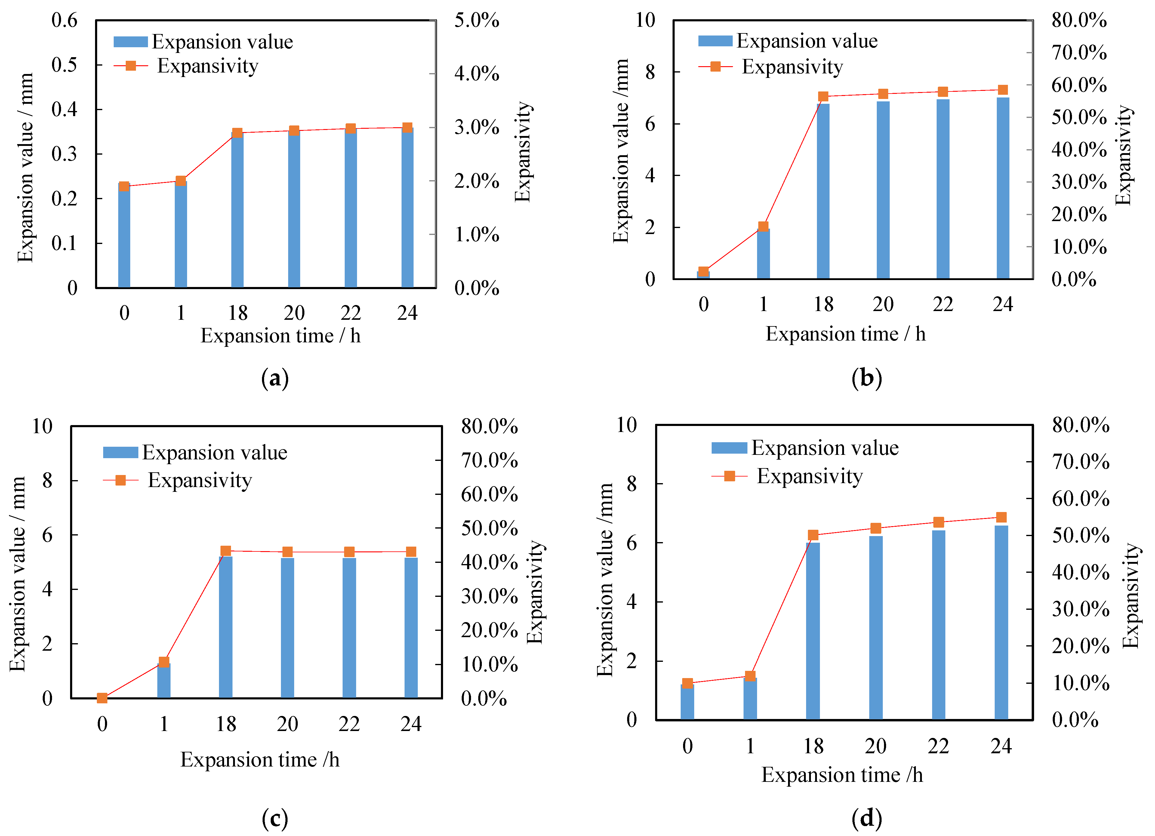
2.2.1. Inhibitory Evaluation

The 8:2 oil-based drilling fluid formula was used to carry out the swelling test. Test method: press the core with 10 g calcium bentonite powder at 13.5 MPa ∗ 5 min, compare the inhibition of oil-based drilling fluid with 10% KCl, 25% CaCl2 and purified water, and test the swelling test results, as shown in the table.
The optimized oil-based drilling fluid formula has good inhibition performance, which is shown in Figure 1. Compared with a 10% KCl solution and a 25% CaCl2 solution, the 24 h expansion rates of the oil-based drilling fluid are 58.50% and 43.05%, respectively. The expansion rate of the oil-based drilling fluid is far lower than that of other inorganic inhibitor solutions. Only in the initial stage is there is micro expansion due to surface wetting, which is only 3%.

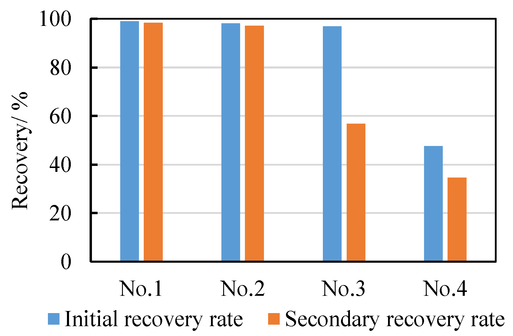
2.2.2. Recovery Rate Experiment

No.1: optimized oil-based drilling fluid: white oil base, O/W = 8:2, density 1.8 g/cm3, 25% CaCl2.
No.2: oil-based drilling fluid: white oil-based, O/W = 8:2, density 1.8 g/cm3, 25% CaCl2.
No.3: potassium chloride polysulfonate drilling fluid, density 2.02 g/cm3, PV = 91 mPa.s, YP = 39 Pa, FL = 3.1 mL.
No.2: purified water.
The experimental results show that the double recovery rate of the optimized oil-based drilling fluid shows almost no significant change, indicating that the rock surface has become lipophilic and is no longer affected by hydration dispersions (Figure 2). The double recovery rate of the oil-based drilling fluid is higher than that of the 2 # imported oil-based drilling fluid, indicating good suppression. The primary recovery rate of potassium chloride polysulphate drilling fluid is similar to that of the oil-based drilling fluid, but its secondary recovery rate is much lower than that of the latter; this indicates that oil-based drilling fluids have much higher suppression and dispersal capacities than water-based drilling fluids, and that the insufficient inhibition stability of water-based drilling fluids is essential.

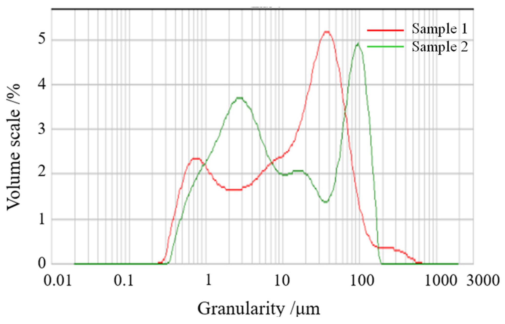
2.2.3. Particle Size Analysis and Evaluation

A laser particle size analyzer MASTERSIZER3000 (Malvern Instruments Co., Ltd., Malvern, UK) was used in the experiment, and the detection range is 0.01~3500 μm. The laser particle size analysis of the oil-based drilling fluid is shown in Figure 3. According to the particle size distribution diagram, oil-based drilling fluid d (0.1): 1.048 μm, d (0.5): 7.958 μm, d (0.9): 105.206 μm. The small size of the particle in the drilling fluid allows it to be used as a filling particle to fill the microfracture of the Longmaxi. At the same time, the solid particles work together to improve the mud cake quality, forming ultra-low-permeability mud cakes in the formation and the plugged surface layer, to meet the requirements of forming ultra-low-permeability plugging layers during the plugging process for the purposes of “blocking fractures”.

2.2.4. Anti-Pollution Performance Evaluation

The anti-pollution performance of the oil-based drilling fluid system, especially the anti-drilling cuttings, anti-water pollution, salt resistance, calcium resistance, and other properties involved, was comprehensively evaluated, which is shown in Table 4.
Formula 1: 1.9 g/cm3 oil-based drilling fluid + 10% 60–100 mesh drilling cuttings
Formula 2: 1.9 g/cm3 oil-based drilling fluid + 5% water
Formula 3: 1.9 g/cm3 oil-based drilling fluid + 10% drilling cuttings + 5% water
The optimized oil-based formula has good resistance to rock cuttings and water pollution. When the drilling cuttings are 10% and the water dosage is 5%, the slurry has little influence on the rheology and water-loss control of the slurry. At the same time, the demulsification voltage is greater than 600 V, and the oil-based drilling fluid has good emulsion stability.
Optimized oil-based formulations have good salt resistance and calcium pollution resistance. Anhydrous calcium sulfate and NaCl have little effect on the rheology and water loss of the slurry. At the same time, the detoxification voltage is larger than 600 V and the oil-based drilling fluid has good emulsion stability, which is shown in Table 5.

2.2.5. Sealing Performance Evaluation

A sand bed plugging test (40–60 meshes) was conducted under a normal temperature and medium pressure. According to the experimental evaluation, the intrusion depth of the oil-based drilling fluid at a normal temperature was 0.5 cm within 30 min, indicating the strong plugging ability of the oil-based drilling fluid.
(1)
Evaluation of the plugging performance of a sand bed under high temperatures and pressures
Experimental scheme: clean the sand passing 40~60 meshes and dry it for standby. Add 200 g (40~60 mesh) sand into the water-loss cylinder with a high temperature and a high-pressure filter to pave the sand bed. Slowly add 400 mL of the oil-based drilling fluid to the water-loss cylinder of the HTHP filter loss instrument. Water-loss cylinders and pressure manifolds were installed and the temperature was raised to the test temperature. Then, it was gradually pressurized to 3.5 MPa; the filtration at 200 °C for 30 min was zero, indicating that the oil-based drilling fluid has a good plugging effect.
(2)
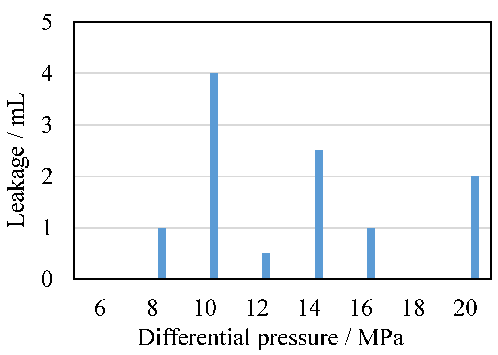
Evaluation of the sealing and leakage prevention of microcracks
All kinds of plugging materials in oil-based drilling fluid can effectively plug microfractures, help to stabilize the wellbore, and prevent the leakage of unstable shale with microfractures.
At 200 °C × 6 h, the drilling fluid was aged and mixed under the condition of 16 h hot rolling, and then the plugging effect of the aged drilling fluid on microfractures of different sizes was evaluated. The microfractures were simulated with steel core parallel fractures of 100 µm, 200 µm, and 300 µm width and 2 mm length, and the experiment was carried out at 200 °C with the micro-fracture plugging tester. From the experimental results shown in Figure 4, oil-based drilling fluid can block 100 µm and 200 µm microcracks, and also can block 300 µm microcracks very well, and no obvious leakage occurs under a 20 MPa high-pressure difference. This indicates that the preferred oil-based drilling fluid has good sealing and leak-prevention abilities, can effectively reduce liquid phase invasion, blocks wellbore prevention and reduces drilling fluid leakage, thus reducing the occurrence of complex situations such as wellbore collapse.

2.2.6. Field Test of Oil-Based Drilling Fluid Performance

A small-scale drilling fluid performance test was conducted at the site. The test parameters for the drilling fluid performance test are shown in Table 6. After three weeks of full circulation of the optically modified drilling fluid, all metrics were in compliance with API standards. The effect of reducing the HTHP filtration of the drilling fluid is evident in the improved quality of the mud cakes, which are smooth, dense, and flexible, with little effect on the rheology of the drilling fluid.
It can be concluded from Table 6 that, after adding the modified starch and polyamine anti-slough inhibitors, the viscosity and shear force of the drilling fluid increases and the water-loss reduction is good. The application of the high-temperature modified starch polyamine drilling fluid technology to the second spud of a deep shale gas horizontal well in the Southwest area of China has effectively reduced the rate of complex incidents such as sticking, mud bagging, and reaming when encountering obstacles in the second spud section.

2.3. Application

Given the environmentally polluting and high-cost characteristics of oil-based drilling fluids, these drilling fluids are largely recycled. This process generally includes two aspects: first, oil-based drilling fluids are recycled after well completion, and second, oil-based drilling waste is recycled after processing.

2.3.1. Performance Analysis of Oil-Based Drilling Fluid

Based on an analysis of its performance at the site, the tested drilling fluid demonstrated excellent stability and rheological properties, strong lubrication inhibition, a high-temperature and high-pressure filtration rate of 3.8 mL, and a rolling recovery rate of 96%. See Table 6 for specific performance parameters. The particle size analysis shows that the size and grain size of the drilling fluid are reasonable and have a strong ability to plug and avoid leakage during drilling. From field observations of oil-based drill cuttings, it is found that the returned drill cuttings are completely non-dispersive. Combined with the analysis of the hole diameter expansion rate of the drilling fluid, the oil-based drilling fluid has strong inhibition, is conducive to the stability of the borehole wall and the safety of downhole drilling, can prevent the damage of the strong water sensitive reservoir, and achieves the purpose of protecting the reservoir (Table 7).
Compared to water-based drilling fluids, oil-based drilling fluids can significantly improve penetration rates, shorten the drilling cycle, effectively reduce the time the drilling fluid is immersed in the gas reservoir, reduce the level of contamination to the gas reservoir, and save drilling costs (Table 8). The recycling of drilling cuttings and waste oil can reduce the pressure of environmental protection and reduce the comprehensive cost. The density of the waste oil recovered from cuttings after environmental protection treatment is more than 1.3 g/cm3, and it contains a large number of low-density and low-quality solids, which affects the performance maintenance of drilling fluid. If it is to be reused, further optimization of the waste oil treatment scheme for cutting recovery should be carried out.

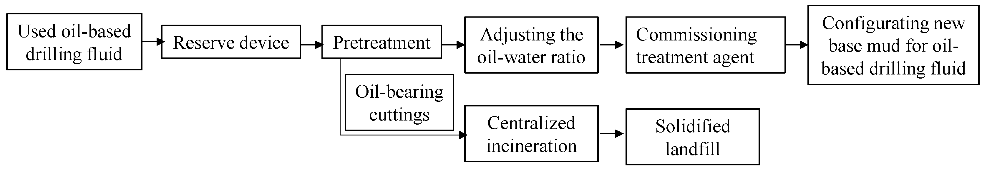
2.3.2. Disposal and Reuse Process of Oil-Based Drilling Fluid after Well Completion

First of all, a reserve station shall be established, mainly including the reserve tank, centrifuge, shale shaker, desander, agitator, and charging funnel. After the well is completed, the on-site oil-based drilling fluid is recycled to the reserve station and then pretreated. The main purpose is to remove the drilling cuttings and other useless solids from the oil-based drilling fluid used on the site, and the cleaned waste is then sent to the treatment center for treatment. The pretreated oil-based drilling fluid needs further treatment, which mainly includes adjusting the Oil—Water ratio, adding emulsifier and wetting agent, and adding organic colloid content such as organic soil and oxidized asphalt, etc. When its performance is adjusted to a reasonable range, it can continue to be used. Figure 5 shows the process of reusing oil-based drilling fluid after well completion.

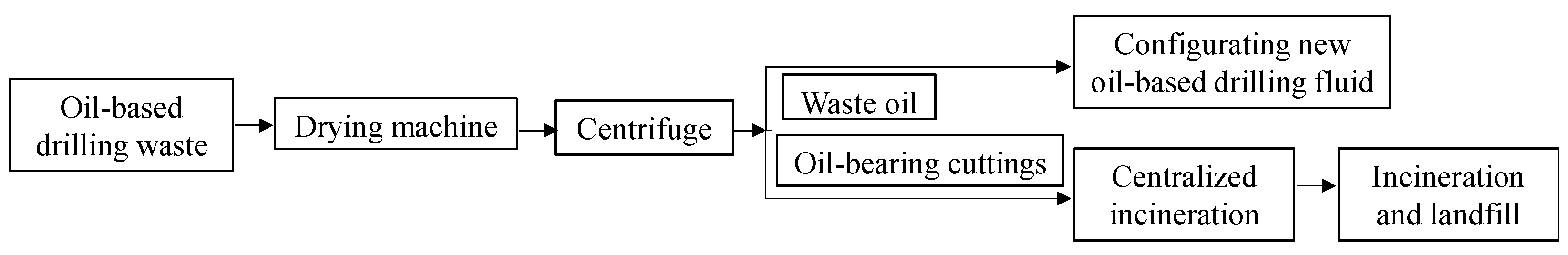
2.3.3. Oil Phase Recovery and the Utilization Process of Oil-Based Drilling Fluid

“Cuttings dryer+ horizontal screw centrifuge” is used to separate oily cuttings while drilling, recover oil-based mud, and realize recycling. After separation, the oil content of cuttings is controlled at 5–10%, and further harmless treatment is carried out after centralized collection, which realizes the recycling of oil-based drilling fluid, saves costs, and improves the possibility of the large-scale promotion of oil-based drilling fluid (Figure 6).
The low oil-to-water high-density oil-based drilling fluid system for deep shale gas can reduce the consumption of oil-based drilling fluids and increase the utilization rate of old mud, thereby reducing the cost of drilling fluids. The highest density of oil-based drilling fluid prepared on site was 2.4 g/cm3, and 300 m3 of oil-based old mud was used. The utilization rate was 54.5 percent for the old slurry and 100 percent for the new slurry. Moreover, the performance of the drilling fluid is stable, ensuring the safe and smooth drilling of deep shale formations.

3. Experiments and Methods

3.1. Experimental Objectives

In view of complex downhole problems such as collapse and leakage in deep shale gas formation drilling, the possible technical problems of collapse and leakage in horizontal well drilling can be solved by optimizing the strong plugging oil-base drilling fluid system. The main optimization ideas are as follows:
(1) A reverse-emulsified oil-based drilling fluid is used to effectively reduce the cost. Oil-based drilling fluid systems have an oil-to-water ratio of 90:10 to 70:30, which gradually increases with density.
(2) Conventional emulsifiers have shortcomings such as poor rheological properties, large dosages, and high comprehensive costs. According to the principle of hydrophilic–lipophilic balance and the relationship between the molecular structure and surface activity of surfactants, this paper selects polymeric surfactants similar to those used in foreign high-performance oil-based drilling fluids to effectively emulsify the Oil—Water interface and improve the emulsion stability and anti-pollution performance of oil-based drilling fluids. At the same time, macromolecular emulsifiers can significantly increase structural forces, improve the rheological properties of drilling fluid systems, and increase the rock-carrying capacity.
(3) The activity of fluid in shale is mostly between 0.5~0.7, which is relatively low. Therefore, it is necessary to adjust the concentration of the aqueous solution of calcium chloride in the oil-based drilling fluid so that its activity ranges from 0.4 to 0.6 to ensure the equilibration of the fluid activity in the shale.
(4) According to the development characteristics of natural fractures in shale reservoir, the width of microfractures is mainly 0.5~15.7 μm. Based on the bridging theory and ideal packing theory, rigid and deformable nano-micron plug materials with a reasonable range of particle sizes were designed to effectively seal joint fissures with nano-micron strong plug agents to reduce filtrate intrusion.

3.2. Experimental Reagents and Devices

3.2.1. Preparation of the Oil-Based Drilling Fluid

The fluid comprised a base oil (white oil), barite, calcium chloride, calcium hydroxide (industrial grade), main emulsifier, auxiliary emulsifier, traditional organic soil, high-temperature resistant organic soil, fluid loss agent, and drilling cuttings.
Add the primary and secondary emulsifiers to the base oil and stir at high speed for 5 min, then add the calcium hydroxide and stir at high speed for 3 min. Add the organic soil and mix at high speed for 3 min. Add 25% of the calcium chloride solution at a high speed and stir at high speed for 10–15 min. Add the strained reduction and stir at high speed for 5 min; then, add the adatoms to the desired density and stir at high speed for 20 min. Continue to add the drill cuttings, mix at high speed for 5 min, put them into an aging tank, and place them in a high-temperature roller furnace for constant temperature aging.

3.2.2. Experimental Devices

The devices used included a six-speed rotating viscometer, a decontamination voltage tester, a high-temperature and high-pressure filter loss tester, and a high-temperature roller.

3.3. Preparation of Oil-Based Drilling Fluid Formula

3.3.1. Determination of the Base Oil and Oil—Water Ratio

The Oil—Water ratio of the common oil-based drilling fluid system is generally controlled between 70:30 and 90:10. Considering the stability and cost of the oil-based drilling fluid, 0 # diesel oil and the Oil—Water ratio of 80:20 are studied and selected as the basis for the next treatment agent optimization evaluation and formula commissioning, which is shown in Table 9.

3.3.2. Mechanism Analysis of the Organic Soil, Emulsifier, and Fluid-Loss Agent

In order to make the performance of the oil-based drilling fluid easy to adjust, solid treatment agents such as organic soil, oxidized asphalt, lipophilic lignite, and manganese dioxide are often dispersed in the oil phase of oil-in-oil emulsion drilling fluids. These solid treatment agents are collectively referred to as the lipophilic colloid. The most commonly used is organic soil, which is primarily used to increase the viscosity and shear force of the drilling fluid and to reduce the filtration of the drilling fluid. The lipophilic mechanism of organic soil is as follows:
The main component of bentonite is layered aluminosilicate montmorillonite. The basic structural layer of montmorillonite is composed of one aluminosilicate octahedral sheet and two silicosilicate tetrahedral sheets. The silicon–oxygen tetrahedron is composed of one silicon and four equidistant oxygen, three of which are located in the same plane, and which are referred to as the bottom oxygen. Multiple silica tetrahedrons share the bottom oxygen to form a silica tetrahedron sheet, which extends infinitely on the plane to form a continuous hexagonal grid structure. The aluminium–oxygen tetrahedron is composed of one aluminum and six oxygen (or hydroxyl). Similarly, the aluminium–oxygen octahedron sheet is also formed by shared oxygen. It has two parallel oxygen (or hydroxyl) surfaces. In the montmorillonite structure, because both sides of the crystal layer are composed of oxygen, the force between the crystal layers is an intermolecular force (without a hydrogen bond), which is loosely connected, and water can enter easily. On the other hand, due to the large number of lattice substitutions in monolayer Morillonite, it incorporates many exchangeable cations on the crystal surface. After the water enters the crystal layer, these exchangeable cations dissociate in the water, forming a diffusive bilayer that leaves the crystal surface negatively charged, so that the clay is responsible for adsorption and condensation. However, bentonite can only exhibit these properties in polar solvents, limiting the use of bentonite in non-polar solvents.
In order to enable bentonite to be used in non-polar solvents, the cationic surfactant quaternary ammonium salt with a positive charge is selected to adsorb on the surface of clay minerals through the formation of ionic bonds, taking advantage of the negative charge on the surface of bentonite. Because the surface of calcium montmorillonite mainly contains Ca2+, Mg2+, and a small amount of Na+, K+, these cations react with water to disperse the clay. Because the hydration effect of Na+ is greater than that of divalent cations, in order to accelerate the action of clay and quaternary ammonium salt surfactant, before using calcium montmorillonite to synthesize cover, Ca2+ or Mg2+ is first replaced with Na+, and then covered with quaternary ammonium salt cationic surfactant. The reaction formula is as follows:
Ca-bentonite + 2Na+ → 2Na-bentonite + Ca2+
Na bentonite + [(R4N) + Cl] → bentonite-NR4 + Na+
The ammonium group in the quaternary ammonium salt enters into the crystal layer and is adsorbed on the clay surface. The hydrocarbon group of the quaternary ammonium salt is covered on the surface of the bentonite, covering its polar point. The clay changes from hydrophilic to hydrophilic, showing good lipophilicity, and ensuring full dispersion in the oil-based drilling fluid.
Excessive filtration of oil-based drilling fluids can severely affect their rheological properties, increase maintenance and disposal costs, and leak large amounts of oil, resulting in significant waste. Therefore, it is important to reduce the filtration of oil-based drilling fluids.
There are three factors that affect the fluid-loss performance of oil-based drilling fluids: namely, the stability of the emulsion, the organic soil, and the fluid-loss additive. The stability of the emulsion in the water-in-oil drilling fluid is the determining factor. The instability of the emulsion results in the poor performance of the system, with neither organic soil nor filtrate reducers being able to play a role. Organic soils are well dispersed in oil-based drilling fluids and react with fine droplets to form structures that increase the viscosity of the system and reduce filtration. The filtrate reducer must be well dissolved or dispersed in the oil phase. It can reduce the filtrate loss by emulsification or wetting, reduce the flow of oil through the filter cake near the interface of emulsion droplets and solid particles, and reduce the filtrate loss by adsorbing and depositing with other lipophilic colloids in the system on the well wall to form a compact filter cake.

3.3.3. Analysis of the Action Mechanism of the Emulsifier

In order to form a stable water-in-oil emulsion drilling fluid, emulsifiers must be selected and used. The main action mechanisms of emulsifiers are as follows:
(1) Reducing the interfacial tension between Oil—Water two-phase liquids
The molecular structure of the emulsion has both hydrophilic and hydrophilic groups, which can exist on the Oil—Water interface. One end of the hydrophilic group extends into the oil phase and the other end of the hydrophilic group extends into the water phase. Therefore, the oil-water interfacial tension is reduced, the remaining surface free energy on the interface is offset, and the trend of the Oil—Water combination is hindered and reduced.
(2) Forming a solid boundary facial mask
The emulsifier is gathered at the interface of the two liquids to form a stable emulsified base with a certain strength. Notably, when the composite emulsifier is used, a “composite” layer with greater strength can be formed. The inevitable results are as follows:
Further reducing the interfacial tension is beneficial to emulsification.
According to the Gibbs function, a decrease in the interfacial tension will result in a decrease in the surface Gibbs free energy and the system will tend to stabilize, which can form a more compact molecular arrangement and greatly increase the strength of the in-plane face mask.
The charge carried by the droplets is increased, increasing the repulsive force between the emulsion droplets, and making them collide with each other during the endless Brownian motion of the dispersed phase droplets in the system, which is not easy to break. This prevents the droplets from becoming larger and reducing the stability of the emulsion. This is also one of the main reasons for using two or more mixed emulsifiers to form a “composite film” on the interface to improve the emulsification effect and increase the stability of the emulsion.
(3) Increase external phase viscosity
Most of the emulsifiers used in water-in-oil drilling fluids have an amphiphilic structure, and the HLB value of the main emulsifier is generally less than 6 so it constitutes a lipophilic surfactant, and the cross-section diameter of its lipophilic (non-polar) group is larger than that of the hydrophilic (polar) group. When the concentration of the main emulsifier in the oil phase exceeds the cmc (critical micelle concentration), the main emulsifier is in approximate dynamic equilibrium on the Oil—Water interface layer (adsorption state) and in the oil phase (dissolution state) in the oil-based drilling fluid. The dosage of the main emulsion is generally much larger than its cmc in the oil phase, so a considerable amount of the main emulsion will enter the outer phase, which increases the viscosity of the outer phase, and, to some extent, affects the rheological properties of the oil-based drilling fluid system.

3.4. Performance Evaluation Method

(1) Emulsification efficiency test
Take 240 mL of base oil into a high stirring cup, add 6.0 g of emulsifier, stir at high speed for 5 min at 1000 rpm, add 60 mL of 25% calcium chloride solution, and stir at high speed for 20 min. After the solution is placed in the aging tank, put it into the high-temperature roller furnace, with 32 H constant-temperature rolling for 16 h. Take it out, cool it to room temperature, stir it at high speed for 20 min, pour it into a 500 mL measuring cylinder, stand and observe, and read the volume of the separated oil layer at different times (V, mL). Calculate the emulsification efficiency w according to Equation (1):
W = 300 V 300 × 100 %
(2) Performance test of oil-based drilling fluid
Refer to the API international test standards to test the rheology, filtration, and electrical stability of the oil-based drilling fluid.

3.5. Limitations of Oil-Based Drilling Fluids

Oil-based drilling fluids are more likely to pollute the environment. Once on the surface, they can cause serious environmental contamination. Therefore, liquid spills should be avoided and ecological environmental pollution should be prevented during the use of oil-based drilling fluids. Once a leak begins, environmental protection measures should be implemented immediately.

4. Conclusions

(1) We conducted an experimental evaluation and optimization of polymer surfactants, such as the main emulsion and auxiliary emulsion of high-performance oil-based drilling fluids. We designed a rigid and deformable nanoparticle plugging agent with reasonable particle size range, and developed an oil-based drilling fluid system with a low Oil—Water ratio at different densities.
(2) The developed oil-based drilling fluid system with a low Oil—Water ratio and high density has a temperature resistance of 200 °C, an Oil—Water ratio of 70:30, and a fracturing fluid pollution rate of 10%. Only barite was used to weigh the drilling fluid, which had a maximum density of 2.6 g/cm3.
(3) The application of a low Oil—Water ratio and strong plugging high-density oil-based drilling fluid technology in deep shale horizontal wells effectively reduces the occurrence rate of complex accidents such as sticking, mud bags, holes expanding, etc. When encountering obstacles in the second spud section, it reduces the consumption of oil-based drilling fluid, improves the utilization rate of old mud, saves drilling costs, and effectively supports the high-quality and rapid drilling and completion technology of horizontal wells.

Author Contributions

Z.S.: conceptualization, funding acquisition, project administration, resources, and software. Z.S., H.Z. (Heng Zhang) and S.L.: data curation, formal analysis, methodology, writing—original draft, and writing—review and editing. M.W.: project administration, resources. C.G.: investigation, methodology, software, and visualization. H.Z. (Haotian Zhang): conceptualization, funding acquisition, methodology. X.Y.: investigation, methodology, project administration. All authors have read and agreed to the published version of the manuscript.

Funding

This work was supported by the National Natural Science Foundation of China: Study of the dynamic characteristics of methane/carbon dioxide in shale heterogeneous reservoirs under multi-field coupling (Program No. 41772150).

Institutional Review Board Statement

Not applicable.

Informed Consent Statement

Not applicable.

Data Availability Statement

Not applicable.

Acknowledgments

The authors are grateful for the support of the National Natural Science Foundation of China. Thanks to the reviewers and editors for their careful review of this manuscript.

Conflicts of Interest

The authors declare no conflict of interest.

References

  1. Guo, T. Progress and research direction of deep shale gas exploration and development. Reserv. Eval. Dev. 2021, 11, 1–6. [Google Scholar]
  2. Ma, Y.; Cai, X.; Zhao, P. China’s shale gas exploration, and development: Understanding and practice. Pet. Explor. Dev. 2018, 45, 561–574. [Google Scholar] [CrossRef]
  3. Nie, H.; He, Z.; Liu, G.; Zhang, G.R.; Lu, Z.Y.; Li, D.H.; Sun, C.X. Status and direction of shale gas exploration and development in China. J. China Univ. Min. Technol. 2020, 49, 13–35. [Google Scholar]
  4. Long, S.; Feng, D.; Li, F.; Du, W. Prospect of the deep marine shale gas exploration and development in the Sichuan Basin. Nat. Gas. Geosci. 2018, 29, 444–451. [Google Scholar]
  5. Yang, L.; Zhaojie, X.; Zhe, C.; Haijun, J.; Ruyue, W. Progress and development directions of deep oil and gas exploration and development in China. China Pet. Explor. 2020, 25, 45–57. [Google Scholar]
  6. Haque, A.E.; Qadri, S.T.; Bhuiyan, M.A.H.; Navid, M.; Nabawy, B.S.; Hakimi, M.H.; Abd-El-Aal, A.K. Integrated wireline log and seismic attribute analysis for the reservoir evaluation: A case study of the Mount Messenger Formation in Kaimiro Field, Taranaki Basin, New Zealand. J. Nat. Gas. Sci. Eng. 2022, 99, 104452. [Google Scholar] [CrossRef]
  7. Adelu, A.O.; Aderemi, A.A.; Akanji, A.O.; Sanuade, O.A.; Kaka, S.I.; Afolabi, O.; Olugbemiga, S.; Oke, R. Application of 3D static modeling for optimal reservoir characterization. J. Afr. Earth Sci. 2019, 152, 184–196. [Google Scholar] [CrossRef]
  8. Qadri, S.T.; Islam, M.A.; Shalaby, M.R. Three-dimensional petrophysical modelling and volumetric analysis to model the reservoir potential of the Kupe Field, Taranaki Basin, New Zealand. Nat. Resour. Res. 2019, 28, 369–392. [Google Scholar] [CrossRef]
  9. Osinowo, O.O.; Ayorinde, J.O.; Nwankwo, C.P.; Ekeng, O.M.; Taiwo, O.B. Reservoir description and characterization of Eni field Offshore Niger Delta, southern Nigeria. J. Pet. Explor. Prod. Technol. 2018, 8, 381–397. [Google Scholar] [CrossRef] [Green Version]
  10. Zhuang, G.; Zhang, Z.; Fu, M.; Ye, X.; Liao, L. Comparative study on the use of cationic-nonionic-organo-montmorillonite in oil-based drilling fluids. Appl. Clay Sci. 2015, 116–117, 257–262. [Google Scholar] [CrossRef]
  11. Humood, M.; Ghamary, M.H.; Lan, P.; Iaccino, L.L.; Bao, X.; Polycarpou, A.A. Influence of additives on the friction and wear reduction of oil-based drilling fluid. Wear 2019, 422–423, 151–160. [Google Scholar] [CrossRef]
  12. Haofu, F.; Yanbin, Z.; Jincheng, Z.; Haiping, Z. Difficulties and countermeasures of deep shale gas drilling technology. Drill. Prod. Technol. 2019, 42, 20–23. [Google Scholar]
  13. Zhang, D.; Deng, J.; Li, D. The law of wellbore instability in non⁃water sensitive gas shales. Sci. Technol. Eng. 2013, 13, 10268–10271. [Google Scholar]
  14. Chen, L.; Hu, J.; Geng, D.; Li, Z. A new technology of plugging and collapse prevention with oil-based drilling fluid in Chongqing shale gas wells. Pet. Reserv. Eval. Dev. 2021, 11, 527–535. [Google Scholar]
  15. Wang, L.; Tang, G.; Han, H. Domestic research on drilling fluid technology for shale reservoir. Drill. Prod. Technol. 2017, 40, 22–25. [Google Scholar]
  16. Chen, H.; Luo, M.; Jiang, D.; Wu, Y.; Ma, C.; Yu, X.; Wang, M.; Yang, Y.; Liu, H.; Zhang, Y. Research on the Formation and Plugging Risk of Gas Hydrate in a Deepwater Drilling Wellbore: A Case Study. Processes 2023, 11, 488. [Google Scholar] [CrossRef]
  17. Liao, G.; Guo, S.; Wang, C.; Shen, Y.; Gao, Y. Pressure Relief-Type Overpressure Distribution Prediction Model Based on Seepage and Stress Coupling. Processes 2023, 11, 480. [Google Scholar] [CrossRef]
  18. Andreucci, C.A.; Fonseca, E.M.M.; Jorge, R.N. Bio-lubricant Properties Analysis of Drilling an Innovative Design of Bioactive Kinetic Screw into Bone. Designs 2023, 7, 21. [Google Scholar] [CrossRef]
  19. Yu, C.; Yang, S.; Zhao, S. Borehole wall strengthening with drilling fluids in shale gas drilling. Drill. Fluid Complet. Fluid 2018, 35, 49–54. [Google Scholar]
  20. Yuan, J.; Yang, Y.; Chang, X.; Guan, K.; Jing, G.; Li, Q. Plugging technology of shale gas oil-based drilling fluid and its application in Changning block. Drill. Prod. Technol. 2020, 43, 133–136. [Google Scholar]
  21. Liu, Z.; Li, M.; He, T. Application of high temperatrue high⁃plugging OBM in Well Zu 201-H1. Drill. Prod. Technol. 2019, 42, 122–125. [Google Scholar]
  22. Tao, H.; Maosen, L.; Lanping, Y.; Jin, H.; Sijun, Z.; Bin, T. Application of oil⁃based drilling fluid in shale gas horizontal well in district of Weyuan. Drill. Fluid. Complet. Fluid. 2012, 29, 1–5. [Google Scholar]
  23. Wang, J.; Zhang, J.; Xie, S.; Yan, L. Evaluation and improvement of the performance of oil base drilling fluids for shale gas drilling. Drill. Fluid. Complet. Fluid. 2019, 36, 555–559. [Google Scholar]
  24. Li, H.; Shen, F.; Wu, J.; Li, W.; Ma, Z. Study on performance of a new oil base mud lost circulation material. Drill. Fluid. Complet. Fluid. 2016, 33, 41–44. [Google Scholar]
  25. Mikhienkova, E.I.; Lysakov, S.V.; Neverov, A.L.; Zhigarev, V.A.; Minakov, A.V.; Rudyak, V.Y. Experimental study on the influence of nanoparticles on oil-based drilling fluid properties. J. Pet. Sci. Eng. 2022, 208 (Pt B), 109452. [Google Scholar] [CrossRef]
  26. Bui, B.; Saasen, A.; Maxey, J.; Ozbayoglu, M.E.; Miska, S.Z.; Yu, M.; Takach, N.E. Viscoelastic properties of oil-based drilling fluids. Annu. Trans. Nord. Rheol. Soc. 2012, 20, 33–47. [Google Scholar]
  27. Siddig, O.; Mahmoud, A.A.; Elkatatny, S. A review of the various treatments of oil-based drilling fluids filter cakes. J. Pet. Explor. Prod. Technol. 2022, 12, 365–381. [Google Scholar] [CrossRef]
  28. Lin, S.; Lu, Y.; Liu, Z.; Lu, W.; Hu, P. Novel Water-Based Mud for Low-Permeable Reservoir in South China Sea. Energies 2023, 16, 1738. [Google Scholar] [CrossRef]
  29. Zhang, G.; Wang, H.; Li, F.; Wang, D.; Li, N.; He, S. Effects of Hydration during Drilling on Fracability of Shale Oil Formations: A Case Study of Da’anzhai Section Reservoir in Sichuan Basin, China. Processes 2022, 10, 2313. [Google Scholar] [CrossRef]
  30. Kong, X.; Chen, M.; Zhang, C.; Liu, Z.; Jin, Y.; Wang, X.; Liu, M.; Li, S. Optimization of High Temperature-Resistant Modified Starch Polyamine Anti-Collapse Water-Based Drilling Fluid System for Deep Shale Reservoir. Molecules 2022, 27, 8936. [Google Scholar] [CrossRef]
  31. Liu, Y. Field tests of high-density oil-based drilling fluid application in horizontal segment. Nat. Gas. Ind. B 2021, 8, 231–238. [Google Scholar] [CrossRef]
  32. Zhong, H.; Shen, G.; Qiu, Z.; Lin, Y.; Fan, L.; Xing, X.; Li, J. Minimizing the HTHP filtration loss of oil-based drilling fluid with swellable polymer microspheres. J. Pet. Sci. Eng. 2019, 172, 411–424. [Google Scholar] [CrossRef]
  33. Mettath, S.; Patel, A.; Stamatakis, E.; Young, S. Non-asphaltic, fluid-loss-control agent for high-temperature applications in synthetic-based invert emulsion drilling fluids. In Proceedings of the AADE-11-NTCE-29, AADE Fluids Conference and Exhibition, Houston, TX, USA, 7–9 April 2011. [Google Scholar]
  34. Guichard, B.; Eliokem, V.A.; Friedheim, J.; Lee, J. An organosoluble polymer for outstanding fluid-loss control with minimum damage. In Proceedings of the SPE 107281, European Formation Damage Conference, Scheveningen, The Netherlands, 30 May–1 June 2007. [Google Scholar]
  35. Murphy, E.; Bening, R. Low Fluid Loss drilling Fluid Compositions Comprising Diblock Copolymers. U.S. Patent No. 9394472, 19 July 2016. [Google Scholar]
  36. Ye, C.; Gong, J.; Liu, K.; Pei, J.; Xu, S.; Xu, P. Study on Gas Invasion Behavior of Gas—Liquid Displacement in Fractured Reservoirs. Processes 2022, 10, 2533. [Google Scholar] [CrossRef]
  37. Wang, Q.; Wang, R.; Sun, J.; Sun, J.; Lu, C.; Lv, K.; Wang, J.; Wang, J.; Yang, J.; Qu, Y. Effect of Drilling Fluid Invasion on Natural Gas Hydrate Near-Well Reservoirs Drilling in a Horizontal Well. Energies 2021, 14, 7075. [Google Scholar] [CrossRef]
  38. Zhuang, G.; Zhang, Z.; Jaber, M. Organoclays used as colloidal and rheological additives in oil-based drilling fluids: An overview. Appl. Clay Sci. 2019, 177, 63–81. [Google Scholar] [CrossRef] [Green Version]
  39. Caenn, R.; Chillingar, G.V. Drilling fluids: State of the art. J. Pet. Sci. Eng. 1996, 14, 221–230. [Google Scholar] [CrossRef]
  40. Davison, M.; Jones, M.; Shuchart, C.E.; Gerard, C. Oil-based muds for reservoir drilling: Their performance and cleanup characteristics. SPE Drill. Complet. 2001, 16, 127–134. [Google Scholar] [CrossRef]
  41. Davidson, E.; McMillan, D.N.; Martin, F.; Morton, K.; Lenz, R. Successful deployment of a new stimulation chemical, post horizontal open-hole gravel pack in wells drilled with both waterbased and oil-based drill-in-fluids. In Proceedings of the SPE/IADC Indian Drilling Technology Conference and Exhibition. Society of Petroleum Engineers, Mumbai, India, 16–18 October 2006. [Google Scholar] [CrossRef]
  42. Guo, H.; Vocken, J.; Opstal, T.; Dams, R.; Zitha, P.L.J. Investigation of the mitigation of lost circulation in oil-based drilling fluids using additives. In Proceedings of the SPE Int Symp Exhib Form Damage Control, Lafayette, LA, USA, 15–17 February 2012. [Google Scholar] [CrossRef]
  43. Hossain, M.; Al-Majed, A.A. Drilling Fluids. In Fundamentals of Sustainable Drilling Engineering, Wiley Online Books; Scrivener Publishing LLC: Beverly, MA, USA, 2015; pp. 73–139. [Google Scholar]
  44. Brege, J.J.; El Sherbeny, W.I.A.; Quintero, L.; Jones, T.A. Using microemulsion technology to remove oil-based mud in wellbore displacement and remediation applications. In Proceedings of the North Africa Technical Conference and Exhibition, Cairo, Egypt, 20–22 February 2012. [Google Scholar] [CrossRef]
  45. Mahmoud, M.; Elkatatny, S. Towards a Complete Removal of Barite Weighted Water and Oil Based-Drilling Fluids in Single Stage. In Proceedings of the SPE Annual Technical Conference and Exhibition, San Antonio, TX, USA, 9–11 October 2017. [Google Scholar] [CrossRef]
  46. Wang, C.; Meng, R.; Xiao, F.; Wang, R. Use of nanoemulsion for effective removal of both oil-based drilling fluid and filter cake. J. Nat. Gas. Sci. Eng. 2016, 36, 328–338. [Google Scholar] [CrossRef]
  47. Sayindla, S.; Lund, B.; Ytrehus, J.D.; Saasen, A. Hole-cleaning performance comparison of oil-based and water-based drilling fluids. J. Pet. Sci. Eng. 2017, 159, 49–57. [Google Scholar] [CrossRef] [Green Version]
Figure 1. Expansion rate test results. (a) Oil-based drilling fluid (density 0.94 g/cm3); (b) 10% KCl solution; (c) 25% CaCl2; (d) purified water.
Processes 11 01129 g001
Figure 2. Results of the recovery comparison experiment.
Processes 11 01129 g002
Figure 3. Laser particle size analysis of solid particles in the drilling fluid.
Processes 11 01129 g003
Figure 4. Results of the 300 µm fracture plugging test.
Processes 11 01129 g004
Figure 5. Reuse treatment process of oil-based drilling fluid after well completion.
Processes 11 01129 g005
Figure 6. Oil phase recovery and utilization process.
Processes 11 01129 g006
Table 1. Performance of oil-based drilling fluid.
Aging 16 h6 rpm3 rpmPV
/mPa.s
YP
/Pa
Gel
/Pa/Pa
ES
/V
FLAPI
/mL
FLHTHP
/mL
50 °C65426.83/3.98720.61.8
80 °C87416.24/5.49310.41.8
150 °C64406.14/4.410300.22.2
200 °C43396.02/3.0105102.2
Table 2. Performance of oil-based drilling fluid.
Aging 16 h6 rpm3 rpmPV
/mPa.s
YP
/Pa
Gel
/Pa/Pa
ES
/V
FLAPI
/mL
FLHTHP
/mL
50 °C975574/5.41210--
80 °C121058116/8.412190.42.2
150 °C121056125/8.112450.42.2
200 °C12105712.56.5/1011640.31.8
Table 3. Performance of oil-based drilling fluid.
Aging 16 h6 rpm3 rpmPV
/mPa.s
YP
/Pa
Gel
/Pa/Pa
ES
/V
FLAPI
/mL
FLHTHP
/mL
50 °C121074125/121202--
80 °C131170136/13112702.0
150 °C131175136/13114802.0
200 °C131179146/13116202.0
Table 4. Test results of oil-based drilling fluid resistance to rock cuttings and water pollution.
Type of Drilling FluidExperimental ConditionPV
/mPa.s
YP
/Pa
FLHTHP
/mL
Gel
/Pa
ES
/V
Original drilling fluidAfter hot rolling treatment406.51.63/4856
Original drilling fluid + 10% Drilling cuttings437.51.65/7923
Original drilling fluid + 5% water559.52.87/13678
Original drilling fluid + 10% Drilling cuttings + 5% water579.02.28/14736
Table 5. Test results of the salt and calcium resistance of the oil-based drilling fluid.
Type of Drilling FluidExperimental ConditionPV
/mPa.s
YP
/Pa
FLHTHP
/mL
Gel
/Pa
ES
/V
Original drilling fluidAfter hot rolling treatment406.51.63/4856
Original drilling fluid + 5% NaCl407.01.44/6902
Original drilling fluid + 8% NaCl417.51.44.5/6912
Original drilling fluid + 0.5% CaSO4406.51.63/4892
Table 6. Optimized performance parameters of the modified starch polyamine anti-collapse water-based drilling fluid tested on the wellsite.
TypeGeneral PerformanceHTHPRheological PropertiesSolid ContentOil-Water Ratio
ParameterFV/sFL
/mL
K
/mm
pHG10”
/Pa
G10’
/Pa
FL
/mL
K
/mm
PV
/mPa.s
YP
/Pa
Vs
/%
Cb
/g/L
Cs
/%
Test result70~95≤1.0≤0.5/3~78~12≤4
(200 °C)
≤1.5≤60.05~15≤39.0/≤0.2≥73:27
Table 7. Comparative analysis of the hole diameter expansion rate of oil-based drilling fluid and water-based drilling fluid.
Drilling Fluid TypePolysulfonate Water-Based Drilling FluidPolyamine Oil-Like Drilling FluidOil-Based Drilling Fluid
Average diameter enlargement rate of horizontal section/%A-1HA-2HA-3HA-4HA-5HA-6H
24.516.612.214.610.39.7
Rolling recovery rate/%82.784.384.490.198.197.2
Table 8. Comparative analysis of the penetration rate of oil-based drilling fluid and water-based drilling fluid.
Drilling Fluid TypePolysulfonate Water-Based Drilling FluidPolyamine Oil-Like Drilling FluidOil-Based Drilling Fluid
Average penetration rate of horizontal section
m/h
A-1HA-2HA-3HA-4HA-5HA-6H
1.491.471.922.373.712.63
Table 9. Main performance parameters of the base oil.
Performance Index0 # Diesel Oil5 # Technical White Oil
Density, kg/L0.840.82
Cetane number≥57.7-
Freezing point, °C<0<0
Flash point, °C>55>120
Aniline point, °C5979
Kinematic viscosity, mm2/s4.71/20 °C3~5/40 °C
Sulfur content, %<0.81-
Acidity, mg KOH/100 mL<7-
Disclaimer/Publisher’s Note: The statements, opinions and data contained in all publications are solely those of the individual author(s) and contributor(s) and not of MDPI and/or the editor(s). MDPI and/or the editor(s) disclaim responsibility for any injury to people or property resulting from any ideas, methods, instructions or products referred to in the content.

