Article

Specifics of Electrostatic Precipitation of Fly Ash from Small-Scale Fossil Fuel Combustion

Energy Research Center, Technical University of Ostrava, 17.listopadu 15/2172, Poruba, 708 33 Ostrava, Czech Republic
*
Author to whom correspondence should be addressed.
Processes 2023, 11(3), 808; https://doi.org/10.3390/pr11030808
Submission received: 6 February 2023 / Revised: 28 February 2023 / Accepted: 7 March 2023 / Published: 8 March 2023
(This article belongs to the Special Issue Solid Waste Valorization and Utilization)

Abstract

:
This paper investigates the removal efficiency of a honeycomb electrostatic precipitator (ESP) applied to control particulate matter (PM) emissions from a small-scale boiler with combustion lignite and hard coal. The specifics of the precipitation of emissions from small-scale boilers are discussed, and the design principles for relevant ESPs are presented and used. The ion-induced nucleation of sulfuric acid occurred, causing the drastic penetration of 19 nm particles through the ESP. Despite this, the overall collection efficiency was sufficient to meet the EU’s Ecodesign Directive requirements. Back corona was not detected. The optimal ESP performance is defined with further parameters: a current density of 0.5 mA/m2 at an electric field strength of about 2.7 × 10⁵ V/m; a minimal specific collecting area of ESP (SCA) of 60 m2/(m3/s); and Nt-product of 4.5 × 10¹⁴ s/m3. Such parameters of ESPs should ensure adequate PM emissions control for any type of boiler with similar emissions characteristics. The composition of collected fly ash particles was analysed, and a method for fly ash utilisation was proposed. This research may be helpful for designing ESPs to control PM emissions for small-scale units with fossil fuel combustion.

1. Introduction

Small-scale boilers for heating purposes are currently used by residential and commercial units mainly with solid fuel combustion, including fossil fuels. The present work focuses on the emission of particulate matter (PM) from small-scale boilers with the combustion of lignites and coals. Such fine particles’ atmospheric pollution contributes to smog formation and plays a vital role in growing public health problems associated with respiratory system diseases.
Due to the worldwide distribution and low efficiency of small-scale combustion units, these emissions have become a severe global environmental problem. To prevent this pollution, some legislative limits have been implemented. For example, the EU’s Ecodesign Directive [1] sets a clear limit on the polluting emissions of small-scale boilers; the PM concentration is limited to 40 mg/m3 (0 °C, 101.3 kPa; at reference O2 = 10 vol%).
Some decreases in environmental impact have been observed: a positive social health impact has been confirmed in Ireland since the end of coal use in 1990 [2]. However, the complete prohibition of coal usage for households has not been met with broad support: the relatively low price and availability of fossil fuels are the primary reasons for opposing a more environmentally friendly choice. Currently, fossil fuel combustion for individual heating is still significant and remains the primary household fuel in some countries. Despite renewable energy progress, this trend is predicted to continue until 2050 [3].
The massive improvement of small-scale burning equipment could reduce household emissions [4]. Positive effects on the environment were also observed with fuel refining [5] or using fuel additives [6]. Replacing coal with biomass has a substantially positive effect, as stated in [7] and confirmed in [8]. However, such methods may not always be available, and they may fail to promote the required reduction in ash concentration in very rare cases. Therefore, treating combustion emissions with appropriate gas cleaning technology is necessary to mitigate the air pollution.
High removal efficiency for particles in the submicron size range, low power consumption, and simple maintenance make electrostatic precipitation the most suitable technology to control emissions. A more substantive discussion of technologies to control emissions can be found elsewhere [9].

1.1. Basics of Electrostatic Precipitation

The particle removal in electrostatic precipitators (ESP) is follows. The electric field in a typical ESP is created by applying a high voltage between the discharge and collecting electrodes. The corona discharge initiates at some specific high voltage value, and the gaseous medium becomes ionised. The corona discharge initial voltage and the concentration of generated ions are determined primarily by the discharge electrode design, whose lower curvature results in a higher ion-generating ability [10]. Suspended particles arrive in this medium and charge in this electric field through collisions with generated ions. Due to the Columb force, charged particles redirect to the electrodes and are removed from the gas flow. Cleaned combustion gases leave the apparatus. The removal efficiency for each specific particle size can be predicted using the Deutsch equation [11]:
η ESP = 1 exp w f A V ,
where
w f = EQ p 3 π μ d p · Cc .
The removal efficiency is given by the technological and structural parameters of ESP and the particle size and chemical composition, defining the ability of particles to take charge and remove. The particle charging process is commonly related to (i) the field charging mechanism, which considers the particle is charged by ions moving directly in an electric field, and (ii) the diffusion mechanism, considering that only ions moving randomly due to thermal diffusion can reach the surface of the particle. The field charging mechanism is predominant for large particles, while diffusion charging is vital for particles with diameters less than 100 nm.
The most widely used assumption for the combined action of both charging mechanisms was suggested by White [12], who proposed the approximate charge evaluation for a particle of size Q p as the sum of the individual action of field Q p f and diffusion Q p diff mechanisms.
Q p = Q p f + Q p diff Q p diff = 2 π ε 0 d p e kT b ln 1 + v ¯ e 2 d p Nt 8 ε 0 k b T Q p f = π ε 0 1 + 2 ε 1 ε + 2 Ed p 2 eu i Nt   4 ε 0 + eu i Nt
The time spent by a particle in an ionised medium is essential for particle charging by both mechanisms and can be characterised by the parameter Nt-product—the product of ion concentration (N) and the residence time of the particle in the electric field (t). Nt-product characterises the ability of discharge electrodes to generate an ion concentration together with the size of ESP, ensuring a particular residence time of gases in an electric field.
The ion concentration in corona discharge can be obtained as follows:
N = j u i eE av .
Thus, the precipitation efficiency can be evaluated with technological parameters, which are as follows: the specific collecting area (SCA), defined as the ratio of the collecting area (A) to the gas flow (V); corona current density (j), represented by the total electric current in ESP (I) related to the collecting area (A); the electric field strength (E); and Nt-product. These technological parameters are applicable to every ESP of any type and design.

1.2. Some Specificities of Industrial Electrostatic Precipitation

ESPs have broad application, including in the heating and power generation industry. Industrial ESPs are faced with cleaning significant volumes of combustion gases with high fly ash content with a concentration of the order of tens of grams per cubic meter, represented by particles with a distribution of the size of approximately 2–10 µm. The negligible content of ultrafine particles is stated [13] and has been recently confirmed, e.g., in [14]. A high content of large particles makes the field charging mechanism predominant for particle charging and precipitation in industrial ESPs. The particle charging due to the field charging mechanism is strongly affected by the dielectric constant ε [15], which is dependent on the chemical composition of fly ash particles. The high combustion efficiency of industrial boilers ensures the specific chemical composition of fly ash, characterised by a low carbon content and a high content of mineral compounds. The dielectric constant value for particles emitted from power plants with fossil fuel combustion ranges from 2.25 to 5.6 [16,17,18], affecting the precipitation efficiency.
High removal efficiency is required for these devices, which is achieved by improving the design and operational parameters. Regarding specific industrial emissions, industrial ESPs are mainly multisection devices that tend to increase the distance between the discharge and collecting electrodes. Collecting electrodes are designed to provide the most extensive collection area and to prevent re-entrainment of collected ash by flowing gases. Discharge electrodes are designed to provide a higher possible electric current to increase ions’ concentration. Each section is powered individually, keeping the voltage as high as possible and close to the spark voltage.
Some phenomena that occur in the corona discharge of industrial ESP due to the specifics of industrial emissions should be discussed here.
The formation of secondary aerosol during the dedusting in ESP of the combustion gases from coal-fired power plants was previously identified by Flagan [19]. Later, Sorokin et al. [20] found that the formation of ultrafine fractions of aerosol in corona discharge can be explained by ion-induced nucleation of sulfuric acid vapours, leading to the formation of radicals H2SO4–H2O and their subsequent growth to particles with sizes of 10–50 nm. More detailed information on nucleation in the corona discharge can be found elsewhere [21].
Industry ESP operation can be complicated by the back corona caused by collection on electrodes of fly ash with a high electrical resistivity over 108 Ω m. This negative phenomenon decreases the ESP removal efficiency [12], including the effect of the electrohydrodynamic flow distortion, which impedes the drift and deposition of charged particles on the electrodes [22]. Moreover, the back corona initiates the secondary emission of toxic compounds from the already collected fly ash [23]. The high content of inorganic salts with essentially no organic compounds in fly ash is responsible for low conductivity and causes problems associated with insufficient particle charging and back corona formation. More detailed information on back corona can be found elsewhere [24].
Considering the specifics above, industrial ESPs tend to be designed for each case individually, and the chemical composition of fly ash is of primary importance for industrial ESPs. Nevertheless, modern industrial ESPs can generally be characterised by a high SCA of over 90 m2/(m3/s) and high Nt-product values, exceeding 8 × 10¹⁴ s/m3.

1.3. The Collected Ash Classification and Utilisation

Globally, 25% of the fly ash collected from fossil fuel industrial combustion is recycled [25]; for some developed countries, such as the Netherlands or Italy, this utilisation rate is 100% [26]. More than 15% of recycled ash is used in road construction, 9% is utilised for mine filling, and about 44% is reused in cement or concrete production worldwide [27].
Therefore, fly ash is classified with priority for use in the cement industry into two chemical types, namely class C and class F. Detailed information on this can be found in the American Standard ASTM C618 [28]; some parameters of the chemical composition for fly ash according to ASTM C618 are shown in Table 1.
Data on the characteristics of fly ash collected by ESPs for small boilers and its utilisation methods are lacking in the published literature.

1.4. Distinctions of Electrostatic Precipitation for Small-Scale Combustion

In contrast, PM emissions from modern small-scale boilers are distinguished by relatively low concentrations, averaging about 100 mg/m3. The combustion conditions significantly affect the size distribution of generated particles and their chemical composition. Nevertheless, particles emitted from small installations are distinct in their fine dispersion: the overwhelming majority of particles range from 0.05 to 0.4 μm [29]. The particle chemical composition is generally characterised by a high content of carbon, reducing the electric resistance of particles, and a high content of carbon compounds, increasing fly ash adhesion.
Accordingly, ESP for small boilers should treat small gas volumes with low concentrations of fly ash, represented by ultrafine particles with considerably low removal efficiency. In addition, the size of cleaning apparatus for domestic boilers should be minimised as much as possible if the ESP is integrated as an add-on solution [30] or to be encased in the unused space of the boiler body [31].
Even though the PM emissions from low-scale boilers have been studied in depth, the methods for their suppression are at an early stage of development, with poorly represented research results. An in-depth review of the ESPs used for household combustion was recently carried out by Jaworek et al. [32]. Most of the published work represents experimental research into specific small-scale ESPs without a detailed analysis of the impact of particle properties and the ESP technological parameters of removal efficiency, such as [33]. Therefore, commercially available low-scale boilers equipped with combustion gas dedusting systems are noted in isolated cases.

1.5. The Aims and Novelty of the Research

We believe that small-scale boilers’ emissions control cannot be solved by copying industrial technology but requires new principles for ESP design considering the specifics of emissions and the processes that occur when cleaning these emissions.
Currently, the design of ESPs for small-scale boilers is based mainly on the involvement of complex mathematical resolvers, for example, in [31], or related to sophisticated theoretical models describing the particle transport in an electric field by the convective diffusion equation [34]. For average boiler manufacturers, however, such methods are usually inaccessible; therefore, simplified and less laborious methods are required for practical ESP engineering. To meet these demands, the ESP performance is subjected here to the technological parameters applicable to ESP of any type and construction: the specific collecting area (SCA), the electric field strength (E), corona current density (j), and Nt-product.
The optimal values of ESP technological parameters should be developed, corresponding to the specificity of emissions from small-scale boilers while ensuring the required PM concentration limits. Developing ESPs for small-scale combustion is less individual than for industrial ESPs. So, obtaining optimal values can significantly simplify the process of ESP design and help to optimise the ESP structural parameters at the design stage, minimising its volume and power consumption. In that way, the implementation of electrostatic precipitation technology can be widened for small-scale combustion, contributing to a reduction in global pollution.
The present work examines the ability of a honeycomb ESP to remove particles emitted from a 450 kW boiler with coal and lignite combustion. The investigation focused on:
features of electrostatic precipitation of particles from small-scale boilers;
developing optimal values of the ESP technological parameters to meet the required removal efficiency;
the chemical composition of the collected fly ash in terms of its utilisation.
The results of the present study support the practical engineering of electrostatic precipitators for small-scale coal and lignite combustion along with industrial ESPs used to remove fly ash with similar characteristics.

2. Experimental Setup and Evaluation

The ESP was investigated in the experimental setup shown in Figure 1.
The experimental setup remained unchanged throughout the tests. All experiments were carried out following the standard EN 303-5:2013 [35], which governs testing for boilers with a heat output of up to 500 kW. The combustion gas extraction was provided by a fan (not figured), and this fan was controlled throughout the entire testing to ensure constant negative pressure in the duct.

2.1. Boiler and Fuels
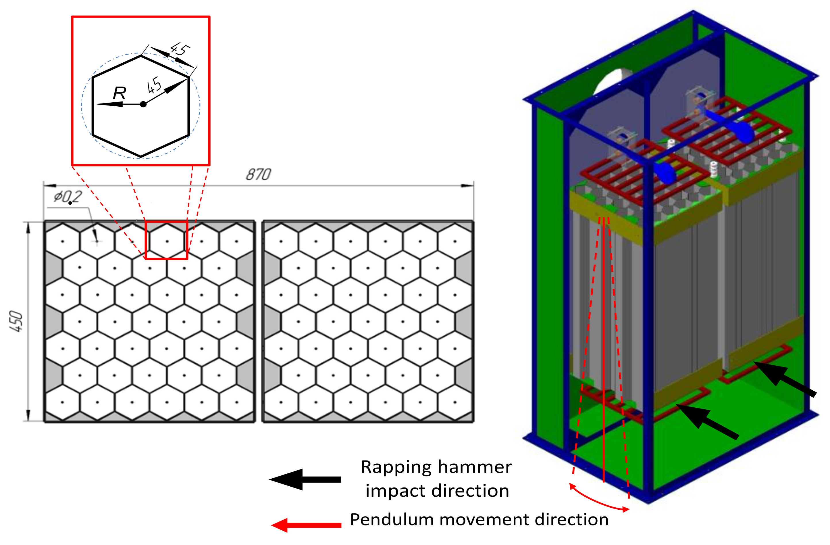
Combustion gases were generated by a typical commercially available 450 kW boiler with automatic feeding by coal and lignite as fuel. The fossil fuels used were typical of those used in Eastern European countries and by local power plants. The fuel composition of the fuels is presented in Table 2.

2.2. ESP

Combustion gases were subjected to uniform distribution and subsequently cleaned in an ESP (Figure 2). The electric field was created by honeycomb collecting electrodes, formed of 78 hexagons of 45 mm in length, and discharge electrodes made of stainless-steel wire with a diameter of 0.2 mm, which were installed along the axis of each hexagon cell. The position of discharge electrodes was fixed by frames installed in the upper and lower parts of each honeycomb section. The active length of the ESP was 1000 mm. The total collecting area of the ESP (A) was 21 m2.
The regeneration was carried out after each series of experiments to keep the electrode surface clean during the testing. The regeneration was provided by a typical hammer/anvil rapping system individually for discharge and collecting electrodes. The collecting electrode rapping system was installed outside the ESP housing. Each section was individually hung by its upper part, allowing the pendulum movement of the section inside the ESP housing. Such a design leads to quite effective regeneration of the collecting electrode surface. Rapping mechanisms for discharge electrode regeneration were installed on the top frames of electrodes.
A high voltage (HV) with negative polarity was generated from an XP Glassmann high-voltage power unit.

2.3. Operating Modes

The boiler was operated in two heat output modes for each fuel type to ensure different conditions for particle precipitation. The high power mode was determined by the technical capabilities of the boiler at 450 kW. The low power mode was settled at 150 kW according to standard EN 303-5:2013.
The change in operating mode determines the flow rate value (V), as well as the fly ash particle concentration and size distribution. The ESP operating mode was settled at voltages of 12.5 kV, providing an electric current value of 40 mA. The changes in the flow gas rate through the ESP ensured a variety of NT-product values. Therefore, the ESP efficiency at various technological parameters could be estimated.
The measurements were carried out under stable boiler operation with a constant CO concentration and flue gas temperature, keeping all experimental conditions close to constant. All the samplings were conducted five times repeatedly for each operation mode, with the ESP alternately turned off/on.

2.4. Sampling Techniques and Analysis

The sampling was conducted downstream of the boiler in the straight duct section with a constant diameter of 250 mm. The sampling points were at least five diameters’ distance from the nearest nonstraightness, according to the EN 303-5:2013 standard requirements. All samples were isokinetic and were conducted strictly in the centre of the gas duct.
An ABB analyser was used to measure combustion gas compounds such as O2, CO, NOx, and CO2, and the gas temperature was measured with a K-type thermocouple.
Gravimetrical measurements for PM concentration were provided according to the norm [36].
The particle number concentration was determined with a Dekati® electrical low-pressure impactor (ELPI), which enables real-time monitoring of the particle number concentration and size distribution.
A detailed description of ELPI operation principles is given in [37]; thorough ELPI performance information is given in [38].
It is known [39] that some results could be distorted by the small particle losses in individual impactor stages due to three loss mechanisms: diffusion, space charge, and image charge deposition. Moreover, some fractions can be measured incorrectly or may not be reflected since their concentrations may be below the detection limit of ELPI [40]. However, ELPI measurement results are quite accurate, are recognised as similar to SMPS and FMPS results for the particle size distribution [41], and are comparable to CPC in terms of total number concentration measurements [42].
Some mismatched measurement results are known to have been recorded for different surfaces of the impactor stages [41]; the bare steel surface was chosen for the impactor stages due to its fair agreement with the measurement results of SMPS.
To adapt the samples to the ELPI operating conditions, a Dekati® FPS-4000 fine particle sampler was used. This dilution system consisted of two stages; in that way, problems of nozzle clogging and condensation were avoided. The initial dilution of the flue gas was involved in the first stage, presented by the perforated tube diluter (PTD). This stage could be heated up to 350 °C. The ejector diluter (ED) was applied in the second dilution stage. In addition to dilution, this system extracted the sample from the flue gases. The mixing chamber connected downstream to the ED ensured a homogeneity of sampled flue gas at the exit from the dilution system. ELPI was connected to the output of this chamber. This dilution system is widespread in sampling from combustion installations, and the inaccuracy introduced by a dilution system was studied and presented in [43]. The dilution ratio was settled at 1:100. An ambient air pumped with a compressor to a pressure of 4.5 bar and subsequently filtered by a HEPA filter to a particle concentration below 2000 #/cm3 was used for dilution. The actual dilution ratio was monitored by comparing the concentrations of CO2 in the flue gas and the sample in the mixing chamber.
The overall and fractional precipitation efficiencies for all regimes were obtained. The overall precipitation efficiency was determined by comparing the total particle concentrations measured during the ESP on/off regimes in both number (#/m3) and mass terms η PM (mg/m3):
η PN PM = 1 C ESP   on C ESP   off .
The ESP collection efficiency as a function of particle size was evaluated in terms of fractional precipitation efficiency η Fi and fractional penetration P Fi .
Fractional penetration P Fi . was determined for each fraction C Fi (#/m3) in the ESP on/off regimes by the changes in particle concentrations for fractions at 6, 13.8, 19, 33.3, 50.7, 98, 169, 315, 590, 910, 1630, 2470, 3660, and 5370 nm:
P Fi = C Fi   on C Fi   off .
The fractional precipitation efficiency η Fi is:
η Fi = 1 P Fi .
The concentration values were normalised to the volume unit of dry gas at 101.325 kPa, 0 °C, and reference O2 at 10%.

3. Results and Discussion

The combustion gases’ composition, temperature, particle size distribution and concentrations, and experimental ESP operation electrical parameters correspond to the previously published ESPs for small-scale boilers, for example, [44,45].
Information about the conditions of the experiments for specific boiler regimes is given in Table 3.

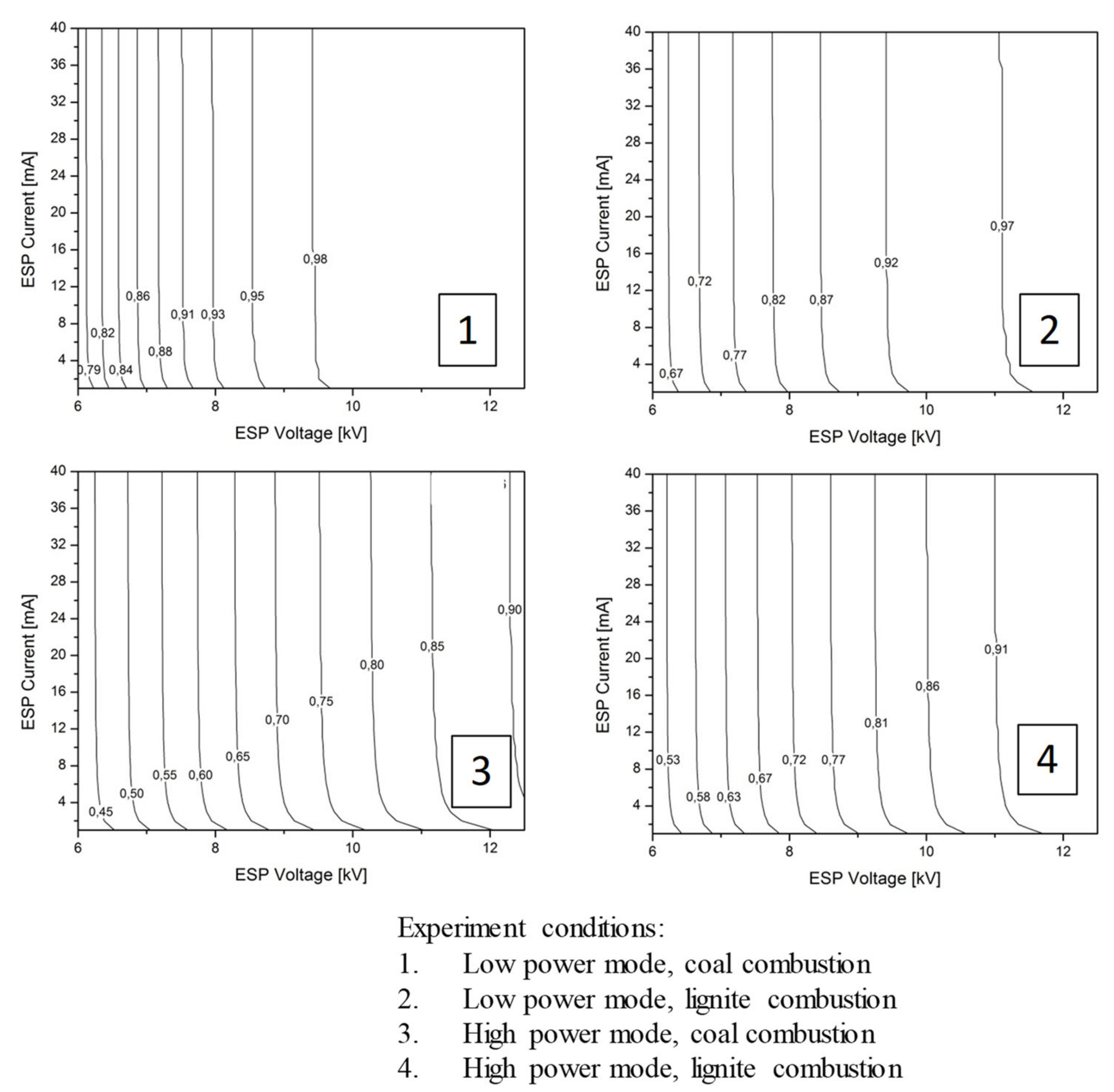
3.1. ESP Performance

The experimental characteristics were obtained for ESP in clean air and are shown in Figure 3. The figure allows for monitoring changes in electric current via the green dotted line in the horizontal plane, with the ion concentration related to ESP voltage and current. Deviations between current–voltage characteristics in clean air and combustion gases under the boiler operating conditions were negligible.
Current and voltage values in the ESP were stable and the same for each experiment. Due to the low input concentration of ash particles, a thick enough layer on the collecting/discharge electrodes could not be formed to change the ESP voltage/current. Therefore, regeneration of the discharge and collecting electrodes was not required during measurements but was carried out after each experiment.
Information about the ESP operation parameters under specific boiler operation regimes is presented in Table 4.
The average value of electric field strength Eav is obtained by dividing applied voltage U by the distance between discharge and collecting electrodes R. The mobility of negative ions ui is accepted at a value of 2.1 × 10⁻⁴ m2/V × s.
In all heat output modes of the boiler, the ESP current–voltage characteristics were observed to have no deviations specific to the formation of a back corona. This can be explained by (i) high carbon concentrations, which clearly reduce the fly ash resistivity, improving precipitation [46]; (ii) significant concentrations of sulphuric oxides in combustion gases [47]. The low specific resistivity of studied fly ash was also predicted to be in the order of 108 Ω·m when using the technique put forward by Bickelhaupt [48], and calculations were confirmed using the prediction method from Zheng et al. [49]. Such resistivity could not affect the removal efficiency [50].
In order to optimise the studied ESP design and performance, ensuring the required removal efficiency, the tested electrostatic precipitator was modelled with varying electric parameters. In this step, the field in the honeycomb cell was approximated to a wire-to-cylinder electrode system. Katsov described the inaccuracy of such approximation as acceptable for engineering practice [51].
The precipitation efficiency was predicted using the Deutsch method (1). Required charge values were obtained (3), respecting the residence time in ESP and based on the calculated ion concentration values (4).
Since the particles with a diameter of 50 nm presented a modal size distribution, the removal efficiency was modelled for these particles; modelling was based on the generally recognised precipitation theory introduced by White [12]. At a specific voltage of the same ESP, the corona current grows with a decrease in the wire diameter. For the studied ESP, the curvature of the discharge electrodes varied when varying the corona current from 4 to 40 mA at each voltage value from 6 to 12.5 kV.
The calculated values for removal efficiency depending on the applied voltage and current generated in the ESP are represented in Figure 4 as isolines. The graph shows that the growth in current had a limited effect on removal efficiency: for all regimes of studied ESP, the modelling demonstrates that a corona current increase over 12 mA had a negligible effect on removal efficiency. In contrast, the impact of the growing applied voltage was uniform. Other research [52] confirms such a conclusion.
However, the measurement results for total removal efficiency appeared lower than theoretically predicted. This discrepancy can be attributed to overestimated particle charge values obtained due to the method used for ESP modelling. The White method, used in this work, involves a simplified theory of diffusion charge based on the kinetic theory of gases. However, the rough approximation of calculation results is a downside of such simplification. White confirmed this inaccuracy of the predictions when comparing his calculations with Arendt and Kallman’s measurements for submicron particles. The results predicted by White were significantly overestimated but were still considered correct due to the “very limited importance” of the diffusion charge in electrostatic precipitation [53]. This statement is true for industrial electrostatic precipitators, and White’s prediction method for such applications is satisfactory in terms of accuracy.
However, the diffusion charging mechanism is highly important for the fine particles of the present study. This assertion is supported by a recent investigation by Zhang et al. [54], who confirmed the negligible influence of the electric field strength and the significant effect of the ion concentration on the charge of small particles. Thus, for ultrafine particles with sizes of 10–100 nm, the electric field strengthening from 1 to 8 kV/m led to a growth in charge only in the order of a few percentage points (1.08% for 10 nm particles), while an almost 100% growth in particle charge was observed when the ion density increased from 1012 to 1016 ions/m3.
Thus, the understated diffusion charging mechanism and rough calculation approximations of the White method [53] led to the overestimation of particle charge in the present work, resulting in inaccurate prediction of ESP efficiency.
For particles of other sizes, the dependence of the removal efficiency on ESP current and voltage values was similar. Therefore, the optimal current density for ESP collecting particles with similar properties was 0.5 mA/m2. Exceeding this value leads to a negligible increase in removal efficiency with a significantly increased power consumption of ESP. This conclusion was confirmed by the dependence of total removal efficiency on Nt-product value (Figure 5).
Figure 5 demonstrates that the Nt-product value exceeding 4.7 × 10¹⁴ s/m3 results in an insignificant increase in ESP removal efficiency. This confirms the conclusion [9] that the Nt-product has a limit of 4.5 × 10¹⁴ s/m3, and growing above this value is impractical because of the negligible growth in ESP efficiency, while the power consumption of the ESP increases dramatically.

3.2. The Changes in Particle Concentration

Average particle size distributions for ESP ON/OFF regimes are shown in Figure 6 for the boiler’s low and high output modes. The number size distributions of emitted particles without precipitation were unimodal, with mode diameters of about 50–80 nm for both fuels. Flagan attributed this peak in particle size distribution to the formation of particles by condensation of vapours during combustion [19].
The ESP fractional efficiency was obtained by processing the results of Equation (7) and presented here as particle penetration for convenience. The inaccuracy in the prediction of the particle charging by the diffusion mechanism discussed above leads to a gross error in calculations of removal efficiency. This demonstrates a need for a more accurate prediction model of the charging of ultrafine particles acceptable for practical engineering.
Significant penetration was observed for particles of 20–40 nm ELPI, which was explained in [55] by the partial electric charge of particles.

3.3. Sulphuric Acid Nucleation

An exceptionally high penetration was observed for 13.8 nm particles: 3.8/1.2 for low/high power regimes with coal combustion and 9.5/7 for low/high power regimes with lignite combustion. The ion-induced nucleation of the sulphuric acid liquid particles was suggested to be responsible for this. Basic information on ion-induced nucleation can be found in some of the studies mentioned below. Sorokin et al. [20] explored the nucleation in binary H2SO4–H2O mixtures and determined the formation of aerosol with diameters of about 2 nm. In his work, Borra (2008) studied the formation of the particles in plasmas of different types of discharge and presented some parameters influencing the formation and growth of the particles.
Mention should be made of the fact that particle penetration is much higher for lignite combustion than for coal combustion; this can be explained by the higher content of sulphur oxides and the moisture in lignite combustion gases.
Figure 7, developed based on the research above, shows a schematic model of particle precipitation, respecting the mechanism for new particle formation due to ion-induced nucleation of sulfuric acid–water clusters. It considers the formation and evolution of neutral and charged clusters with various primary ions (H+, OH, HSO4), basic ligands H2SO4 and H2O, and charged and neutral aerosol particles. In the present work, the authors hypothesised that flue gases entering the ESP exclusively contain suspended particles from combustion. However, with the ESP turned on, secondary aerosols were formed and consequently grew; a portion of these aerosols, directly or due to interaction with suspended particles, was collected in ESP. Therefore, the ESP penetration was represented by newly formed secondary aerosols, coagulated secondary aerosols, a compound of primary particles with secondary aerosols, and unprecipitated initial particles.
The aforementioned ion-induced nucleation research does not allow reliable prediction of ESP efficiency due to the neglect of the primary aerosol from the combustion zone. Since ESPs for coal and lignite combustion have to charge and remove particles that arrived from the combustion zone, and also newly nucleated particles, the accurate prediction of ESP efficiency requires the following processes to be considered: (a) nucleation and coagulation of secondary aerosols in the presence of initial particles; (b) interaction of secondary aerosols with initial particles.
A detailed study of electrostatic precipitation accompanied by nucleation of a second aerosol requires more thorough experiments with different temperature regimes of combustion gases [56] and varying concentrations of sulphur oxides [54]. In addition, high-temperature sampling without required diluting [57] should be used to reduce the measurement error introduced by the dilution system and detection limit of ELPI. This cannot be implemented within the framework of the present study but requires additional research; therefore, nucleation phenomena do not need to be discussed further.

3.4. Chemical Composition of Collected Fly Ash

The chemical composition of fly ash was of particular interest. Therefore, ash precipitated on the ESP electrodes and in the boiler’s heat exchanger was sampled and investigated. Results are presented in Table 5.
The fly ash composition, including a high content of carbon, was recognised as typical for small-scale combustion [29] and corresponded to emissions from modern combustion units [58]. The analysis of samples shows a notable CaO content, indicating the self-cementing properties of fly ash. Compared to industrial ash [59], the samples demonstrate low Al2O3, SiO2, and Fe2O3, so the Σ(SiO2 + Al2O3 + Fe2O3) content in collected fly ash is 42.6% for coal and 38.96% for lignite. The unburned carbon content in collected fly ash far exceeds that in industrial ashes [59,60,61]. The negative impact of high-carboned additives to cementitious material was confirmed in recent in-depth research [62]. These circumstances, together with the high sulphur trioxide content, indicate this ash cannot be used in the cement industry.
The content of trace elements (TE) in ash samples was investigated, and the results are presented in Table 6.
The fly ash collected from the ESP has increased contents of Hg, Pb, Zn, and Cu, indicating the prevention of the emission of these elements into the atmosphere by the ESP. However, reusing this material is problematic, for example, in road construction, due to the high content of heavy metals (see Table 6). Thus, mine filling is proposed as a safe method for the utilisation of fly ash from small-scale boilers with fossil fuel combustion.

4. Conclusions

The specifics of electrostatic precipitation for small-scale boiler combustion were discussed, and design principles for appropriate ESPs were determined and implemented to design a honeycomb ESP to control PM emissions from a 450 kW automatic boiler. Experiments were conducted during the boiler’s nominal regime and a 30% reduced heat output regime with hard coal and lignite combustion.
The following technical parameters were found to be optimal to ensure sufficient removal efficiency: minimal SCA of 60 m2/(m3/s), current density of 0.5 mA/m2, and electric field strength of about 2.7 × 10⁵ V/m. The previously stated Nt-product limit value of 4.7 × 10¹⁴ s/m3 was confirmed in the present work. The above parameters, maintained for ESP operation, ensured a PM concentration in the boiler’s emissions of 7–21 mg/m3 depending on the heat output and fuel used. These values satisfy the limit set by Ecodesign, which is 40 mg/m3.
The above technical parameters are based on electrostatic precipitation principles and do not depend on the ESP type and construction; therefore, the determined values of these parameters can be applied in any ESP to ensure the sufficient control of emissions from any boiler with similar characteristics. Exceeding these parameters does not lead to a significant increase in the efficiency of ESP.
No back corona formation was detected during the experimental testing.
The data presented on collected fly ash composition can be used to solve the utilisation problem for fly ash collected from small-scale boilers.
Nucleation was observed for 14 nm particles, which were suggested to be formed by water and sulphuric acid compounds. Further research should consider this phenomenon.

Author Contributions

Conceptualization, O.M.; methodology, K.K.; software, L.K.; validation, O.M. and K.K.; formal analysis, F.H.; investigation, O.M.; resources, J.H.; data curation, J.R.; writing—original draft preparation, L.K.; writing—review and editing, O.M.; visualization, M.D.; supervision, T.O.; project administration, J.H. All authors have read and agreed to the published version of the manuscript.

Funding

This research received no external funding.

Institutional Review Board Statement

Not applicable.

Informed Consent Statement

Not applicable.

Data Availability Statement

Not applicable.

Acknowledgments

The authors are grateful to Pavel Noskievič, for his contributions. This research did not receive any specific grants from funding agencies in the public, commercial, or not-for-profit sectors.

Conflicts of Interest

The authors declare no conflict of interest.

Symbols and Constants

Am2Total area of collecting electrodes
C Particle concentration
mg/m3Mass
#/m3Number
cESPonmg/m3, #/m3Particle concentration: ESP on-regime
cESPoffmg/m3, #/m3Particle concentration: ESP off-regime
Cc-Cunningham correction factor, Cc = 1 + λ d · 2.514 + 0.8 · e 0.55 · λ d
C Fi   #/m3Number fraction concentration
dpmParticle diameter
E (Eav)V/mElectric field strength (average value)
eCElementary (electron) charge e = 1.6 × 10⁻¹⁹
ImAElectrostatic precipitation current
jmA/m2Electric current density
kbJ/KBoltzmann constant 1.3806488(13) × 10−23
N#/m3Number concentration of ions
RmDistance from discharge wire to collecting electrode
TKAbsolute gas temperature
tsResidence time
uim2/V×sIon mobility
UVESP voltage
Vm3/sVolume flow rate of combustion gases
v ¯ m/sMean thermal velocity of ions
wfm/sParticle drift velocity
Q p CParticle charge
η ESP -Theoretical particle removal efficiency of ESP
e0F/mElectric constant (vacuum permittivity) e0 = 8.85 × 10⁻¹²
ε -Particle dielectric constant (relative material permittivity)
µPa×sDynamic viscosity of gaseous medium

References

  1. C.R.E. 2015/1189, Commission Regulation (EU) 2015/1189 of 28 April 2015 Implementing Directive 2009/125/EC of the European Parliament and of the Council with Regard to Ecodesign Requirements for Solid Fuel Boilers. 2015. Available online: https://eur-lex.europa.eu/legal-content/EN/TXT/?uri=uriserv:OJ.L_.2015.193.01.0100.01.ENG&toc=OJ:L:2015:193:TOC (accessed on 23 January 2023).
  2. Dockery, D.W.; Rich, D.Q.; Goodman, P.G.; Clancy, L.; Ohman-Strickland, P.; George, P.; Kotlov, T.; HEI Health Review Committee. Effect of air pollution control on mortality and hospital admissions in Ireland. Res. Rep. (Health Eff. Inst.) 2013, 176, 3–109. [Google Scholar]
  3. IEA, U.S. Energy Information Administration. 2020. Available online: https://www.eia.gov/outlooks/archive/ieo20/ (accessed on 23 January 2023).
  4. Edwards, R.D.; Smith, K.R.; Zhang, J.; Ma, Y. Implications of changes in household stoves and fuel use in China. Energy Policy 2004, 32, 395–411. [Google Scholar] [CrossRef]
  5. Winijkul, E.; Bond, T.C. Emissions from residential combustion considering end-uses and spatial constraints: Part II, emission reduction scenarios. Atmos. Environ. 2016, 124, 1–11. [Google Scholar] [CrossRef] [Green Version]
  6. Carroll, J.P.; Finnan, J.M. The use of additives and fuel blending to reduce emissions from the combustion of agricultural fuels in small scale boilers. Biosyst. Eng. 2015, 129, 127–133. [Google Scholar] [CrossRef]
  7. Johansson, L.S.; Tullin, C.; Leckner, B.; Sjovall, P. Particle emissions from biomass combustion in small combustors. Biomass Bioenergy 2003, 25, 435–446. [Google Scholar] [CrossRef]
  8. Verma, V.K.; Bram, S.; Gauthier, G.; De Ruyck, J. Evaluation of the performance of a multi-fuel domestic boiler with respect to the existing European standard and quality labels: Part-1. Biomass Bioenergy 2011, 35, 80–89. [Google Scholar] [CrossRef]
  9. Molchanov, O.; Krpec, K.; Horák, J.; Ochodek, T.; Kubonová, L.; Hopan, F.; Ryšavý, J. Optimising parameters for improved electrostatic precipitation of fly ash from small-scale biomass combustion. J. Clean. Prod. 2022, 362, 132352. [Google Scholar] [CrossRef]
  10. Lee, G.-H.; Hwang, S.-Y.; Cheon, T.-W.; Kim, H.-J.; Han, B.; Yook, S.-J. Optimization of pipe-and-spike discharge electrode shape for improving electrostatic precipitator collection efficiency. Powder Technol. 2021, 379, 241–250. [Google Scholar] [CrossRef]
  11. Deutsch, W. Bewegung und Ladung der Elektrizitätsträger im Zylinderkondensator. Ann. Physik 1922, 68. [Google Scholar] [CrossRef] [Green Version]
  12. White, H.J. Industrial Electrostatic Precipitation; Addison-Wesley Publishing Company: Boston, MA, USA, 1963. [Google Scholar]
  13. Ehrlich, C.; Noll, G.; Kalkoff, W.D.; Baumbach, G.; Dreiseidler, A. PM10, PM2.5 and PM1.0—Emissions from industrial plants—Results from measurement programmes in Germany. Atmos. Environ. 2007, 41, 6236–6254. [Google Scholar] [CrossRef]
  14. Hower, J.C.; Clack, H.L.; Hood, M.M.; Hopps, S.G.; Thomas, G.H. Impact of coal source changes on mercury content in fly ash: Examples from a Kentucky power plant. Int. J. Coal Geol. 2017, 170, 2–6. [Google Scholar] [CrossRef]
  15. He, K.; Lu, J.; Ma, X.; Ju, Y.; Xie, L.; Pang, L.; Wang, X.; Chen, J. Effect of maxwell-Wagner relaxation on field charging of particles. Aerosol Sci. Technol. 2015, 49, 1210–1221. [Google Scholar] [CrossRef]
  16. Nelson, S.O. Measurement and calculation of powdered mixture permittivities. IEEE Trans. Instrum. Meas. 2001, 50, 1066–1070. [Google Scholar] [CrossRef] [Green Version]
  17. Sreenivas, V.N.; Karthik, D.; Kumar, V.A.; Sidharth, V.D.; Sundaram, T.M.; Sarkar, S.; Narayanan, S.B. Determination of complex permittivity of fly ash for potential electronic applications. In Applied Mechanics and Materials; Trans Tech Publications Ltd.: Wollerau, Switzerland, 2012; pp. 4292–4296. [Google Scholar]
  18. Tao, Y.; Ding, Q.; Deng, M.; Tao, D.; Wang, X.; Zhang, J. Electrical properties of fly ash and its decarbonization by electrostatic separation. Int. J. Min. Sci. Technol. 2015, 25, 629–633. [Google Scholar] [CrossRef]
  19. Flagan, R.C. Submicron particles from coal combustion. In Symposium (International) on Combustion; Elsevier: Amsterdam, The Netherlands, 1979; Volume 17, pp. 97–104. [Google Scholar]
  20. Sorokin, A.; Arnold, F.; Wiedner, D. Formation and growth of sulfuric acid–water cluster ions: Experiments, modelling, and implications for ion-induced aerosol formation. Atmos. Environ. 2006, 40, 2030–2045. [Google Scholar] [CrossRef]
  21. Borra, J.P. Charging of aerosol and nucleation in atmospheric pressure electrical discharges. Plasma Phys. Control. Fusion 2008, 50, 10. [Google Scholar] [CrossRef]
  22. Krupa, A.; Podliński, J.; Mizeraczyk, J.; Jaworek, A. Velocity field of EHD flow during back corona discharge in electrostatic precipitator. Powder Technol. 2019, 344, 475–486. [Google Scholar] [CrossRef]
  23. Jaworek, A.; Czech, T.; Rajch, E.; Lackowski, M. Laboratory studies of back-discharge in fly ash. J. Electrost. 2006, 64, 326–337. [Google Scholar] [CrossRef]
  24. Masuda, S.; Mizuno, A. Initiation condition and mode of back discharge. J. Electrost. 1977, 4, 35–52. [Google Scholar] [CrossRef]
  25. Huang, B.; Gan, M.; Ji, Z.; Fan, X.; Zhang, D.; Chen, X.; Sun, Z.; Huang, X.; Fan, Y. Recent progress on the thermal treatment and resource utilization technologies of municipal waste incineration fly ash: A review. Process. Saf. Environ. Prot. 2022, 159, 547–565. [Google Scholar] [CrossRef]
  26. Gollakota, A.R.K.; Volli, V.; Shu, C.-M. Progressive utilisation prospects of coal fly ash: A review. Sci. Total Environ. 2019, 672, 951–989. [Google Scholar] [CrossRef] [PubMed]
  27. Loya, M.I.M.; Rawani, A.M. A review: Promising applications for utilization of fly ash. Int. J. Adv. Technol. Eng. Sci. 2014, 2, 143–149. [Google Scholar]
  28. ASTM C618-19; Standard Specification for Coal Fly Ash and Raw or Calcined Natural Pozzolan for Use in Concrete. ASTM International: West Conshohocken, PA, USA, 2019.
  29. Chen, Q.; Zhang, X.; Bradford, D.; Sharifi, V.; Swithenbank, J. Comparison of Emission Characteristics of Small-Scale Heating Systems Using Biomass Instead of Coal. Energy Fuels 2010, 24, 4255–4265. [Google Scholar] [CrossRef]
  30. Eom, Y.S.; Kang, D.H.; Choi, D.H. Numerical analysis of PM2.5 particle collection efficiency of an electrostatic precipitator integrated with double skin façade in a residential home. Build. Environ. 2019, 162, 106245. [Google Scholar] [CrossRef]
  31. Schittl, F.; Unterpertinger, L.; Heschl, C.; Krail, J. Numerical and experimental development of integrated electrostatic precipitator concepts for small-scaled biomass furnaces. Biomass Bioenergy 2021, 154, 106247. [Google Scholar] [CrossRef]
  32. Jaworek, A.; Sobczyk, A.T.; Marchewicz, A.; Krupa, A.; Czech, T. Particulate matter emission control from small residential boilers after biomass combustion. A review. Renew. Sustain. Energy Rev. 2021, 137, 110446. [Google Scholar] [CrossRef]
  33. Al-Hamouz, Z. Numerical and experimental evaluation of fly ash collection efficiency in electrostatic precipitators. Energy Convers. Manag. 2014, 79, 487–497. [Google Scholar] [CrossRef]
  34. Yang, X.F.; Kang, Y.M.; Zhong, K. Effects of geometric parameters and electric indexes on the performance of laboratory-scale electrostatic precipitators. J. Hazard. Mater. 2009, 169, 941–947. [Google Scholar] [CrossRef]
  35. EN 303-5:2013; Heating Boilers—Part 5: Heating Boilers for Solid Fuels, Manually and Automatically Stoked, Nominal Heat Output of Up to 500 kw—Terminology, Requirements, Testing and Marking. European Standard: Brussels, Belgium, 2013. Available online: https://www.en-standard.eu/ilnas-en-303-5-heating-boilers-part-5-heating-boilers-for-solid-fuels-manually-and-automatically-stoked-nominal-heat-output-of-up-to-500-kw-terminology-requirements-testing-and-marking/ (accessed on 23 January 2023).
  36. EN13284-1:2017; Stationary Source Emissions—Determination of Low Range Mass Concentration of Dust—Part 1: Manual Gravimetric Method. European Standard: Brussels, Belgium, 2017. Available online: https://www.en-standard.eu/csn-en-13284-1-stationary-source-emissions-determination-of-low-range-mass-concentration-of-dust-part-1-manual-gravimetric-method/ (accessed on 23 January 2023).
  37. Keskinen, J.; Pietarinen, K.; Lehtimäki, M. Electrical low pressure impactor. J. Aerosol Sci. 1992, 23, 353–360. [Google Scholar] [CrossRef]
  38. Järvinen, A.; Aitomaa, M.; Rostedt, A.; Keskinen, J.; Yli-Ojanperä, J. Calibration of the new electrical low pressure impactor (ELPI+). J. Aerosol Sci. 2014, 69, 150–159. [Google Scholar] [CrossRef] [Green Version]
  39. Virtanen, A.; Marjamäki, M.; Ristimäki, J.; Keskinen, J. Fine particle losses in electrical low-pressure impactor. J. Aerosol Sci. 2001, 32, 389–401. [Google Scholar] [CrossRef]
  40. Marjamäki, M.; Keskinen, J.; Chen, D.-R.; Pui, D.Y.H. Performance evaluation of the electrical low-pressure impactor (ELPI). J. Aerosol Sci. 2000, 31, 249–261. [Google Scholar] [CrossRef]
  41. Leskinen, J.; Joutsensaari, J.; Lyyränen, J.; Koivisto, J.; Ruusunen, J.; Järvelä, M.; Tuomi, T.; Hämeri, K.; Auvinen, A.; Jokiniemi, J. Comparison of nanoparticle measurement instruments for occupational health applications. J. Nanopart. Res. 2012, 14, 718. [Google Scholar] [CrossRef]
  42. Molchanov, O.; Krpec, K.; Horák, J.; Kuboňová, L.; Hopan, F. Predicting efficiency for electrostatic precipitation of fly ash from small-scale solid fuel combustion. Sep. Purif. Technol. 2021, 270, 118807. [Google Scholar] [CrossRef]
  43. Cornette, J.F.P.; Coppieters, T.; Desagher, D.; Annendijck, J.; Lepaumier, H.; Faniel, N.; Dyakov, I.; Blondeau, J.; Bram, S. Influence of the Dilution System and Electrical Low Pressure Impactor Performance on Particulate Emission Measurements from a Medium-scale Biomass Boiler. Aerosol Air Qual. Res. 2020, 20, 499–519. [Google Scholar] [CrossRef]
  44. Bologa, A.; Paur, H.-R.; Ulbricht, T.; Woletz, K. Particle Emissions from Small Scale Wood Combustion Devices and their Control by Electrostatic Precipitation. Aaas10 Adv. Atmos. Aerosol Symp. 2010, 22, 119–124. [Google Scholar] [CrossRef]
  45. Intra, P.; Limueadphai, P.; Tippayawong, N. Particulate Emission Reduction from Biomass Burning in Small Combustion Systems with a Multiple Tubular Electrostatic Precipitator. Part. Sci. Technol. 2010, 28, 547–565. [Google Scholar] [CrossRef]
  46. Barranco, R.; Gong, M.; Thompson, A.; Cloke, M.; Hanson, S.; Gibb, W.; Lester, E. The impact of fly ash resistivity and carbon content on electrostatic precipitator performance. Fuel 2007, 86, 2521–2527. [Google Scholar] [CrossRef]
  47. Bickelhaupt, R.E.; Sparks, L.E. Predicting fly ash resistivity—An evaluation. Environ. Int. 1981, 6, 211–218. [Google Scholar] [CrossRef]
  48. Bickelhaupt, R.E. Research Report, a Technique for Predicting Fly Ash Resistivity; United States Environmental Protection: South Birmingham, AL, USA, 1979.
  49. Zheng, C.; Liu, X.; Yan, P.; Zhang, Y.; Wang, Y.; Qiu, K.; Gao, X. Measurement and prediction of fly ash resistivity over a wide range of temperature. Fuel 2018, 216, 673–680. [Google Scholar] [CrossRef]
  50. Zhang, H.; Wang, Y.; Gao, W.; Wu, Z.; Yang, Z.; Yang, Y.; Wu, W.; Zheng, C.; Gao, X. Minimizing the adverse effects of dust layer on the particle migration in electrostatic precipitator under various temperature. Fuel Process. Technol. 2021, 213, 106659. [Google Scholar] [CrossRef]
  51. Kapcov, N.A. Koronnyj Razryad; Moskva: Moscow, Russia, 1947; pp. 182–185. [Google Scholar]
  52. Nussbaumer, T.; Lauber, A. Monitoring the availability of electrostatic precipitators (ESP) in automated biomass combustion plants. Biomass Bioenergy 2016, 89, 24–30. [Google Scholar] [CrossRef]
  53. White, H.J. Particle Charging in Electrostatic Precipitation. Trans. Am. Inst. Electr. Eng. 1951, 70, 1186–1191. [Google Scholar] [CrossRef]
  54. Zhang, H.; Shao, L.; Gao, W.; Wang, Y.; Liu, X.; Yang, Y.; Zheng, C.; Gao, X. Particle charging in electric field under simulated SO3-containing flue gas at low temperature. Fuel 2022, 310, 122291. [Google Scholar] [CrossRef]
  55. Arrondel, V.; Bacchiega, G. Nanoparticle and fine particle collection efficiency using an electrostatic precipitator: A description of the specific physical processes. In Proceedings of the ICESP 2016, Wrocław, Poland, 19–23 September 2016. Available online: http://demo.nspiresoft.com/isespnew/assets/themes/isesp/papers/xiv/S1.4-Arrondel.pdf (accessed on 23 January 2023).
  56. Zheng, C.; Shao, L.; Wang, Y.; Zheng, H.; Gao, W.; Zhang, H.; Wu, Z.; Shen, J.; Gao, X. Investigation of the growth and removal of particles in coal-fired flue gas by temperature management. Fuel 2021, 302, 121220. [Google Scholar] [CrossRef]
  57. Yang, W.; Pudasainee, D.; Gupta, R.; Li, W.; Wang, B.; Sun, L. An overview of inorganic particulate matter emission from coal/biomass/MSW combustion: Sampling and measurement, formation, distribution, inorganic composition and influencing factors. Fuel Process. Technol. 2021, 213, 106657. [Google Scholar] [CrossRef]
  58. Horák, J.; Kuboňová, L.; Bajer, S.; Dej, M.; Hopan, F.; Krpec, K.; Ochodek, T. Composition of ashes from the combustion of solid fuels and municipal waste in households. J. Environ. Manag. 2019, 248, 109269. [Google Scholar] [CrossRef]
  59. Ozturk, M.; Karaaslan, M.; Akgol, O.; Sevim, U.K. Mechanical and electromagnetic performance of cement based composites containing different replacement levels of ground granulated blast furnace slag, fly ash, silica fume and rice husk ash. Cem. Concr. Res. 2020, 136, 106177. [Google Scholar] [CrossRef]
  60. Bhatt, A.; Priyadarshini, S.; Acharath Mohanakrishnan, A.; Abri, A.; Sattler, M.; Techapaphawit, S. Physical, chemical, and geotechnical properties of coal fly ash: A global review. Case Stud. Constr. Mater. 2019, 11, e00263. [Google Scholar] [CrossRef]
  61. Nathan, Y.; Dvorachek, M.; Pelly, I.; Mimran, U. Characterization of coal fly ash from Israel. Fuel 1999, 78, 205–213. [Google Scholar] [CrossRef]
  62. Gupta, S.; Kashani, A. Utilization of biochar from unwashed peanut shell in cementitious building materials—Effect on early age properties and environmental benefits. Fuel Process. Technol. 2021, 218, 106841. [Google Scholar] [CrossRef]
Figure 1. The experimental setup.
Processes 11 00808 g001
Figure 2. ESP.
Figure 2. ESP.
Processes 11 00808 g002
Figure 3. The ESP current–voltage and ion concentration characteristics.
Processes 11 00808 g003
Figure 4. Expected and obtained precipitation efficiency depended on ESP electric parameters.
Processes 11 00808 g004
Figure 5. The total removal efficiency with NT-product.
Processes 11 00808 g005
Figure 6. Particle size distribution at ESP on/off regimes and ESP penetration.
Processes 11 00808 g006
Figure 7. Schematic model of particle formation and precipitation in the ESP.
Processes 11 00808 g007
Table 1. Classification of fly ash according to ASTM C618 (%).
ClassContent Σ (SiO2 + Al2O3 + Fe2O3) SO3 Content
C≥50≤5
F≥70≤3
Table 2. Fuel composition.
CarbonHydrogenSulphurNitrogenOxygenWaterAsh
Content in coal (mass %)63.13.970.561.066.346.7918.17
Content in lignite (mass %)51.744.030.50.6313.4526.083.57
Table 3. Average experimental conditions for specific boiler regimes.
ParameterUnitLow Power Mode
Coal/Lignite
High Power Mode
Coal/Lignite
Flue gas temperature, T°C71/80120/99
Combustion gas flow rate, V **m3/h453/6671244/970
Content of N2 in flue gasesvol%75.88/74.775.53/71.8
Content of CO2 in flue gasesvol%7.98/5.799.51/11.43
Content of O2 in flue gasesvol%10.9/13.229.03/5.98
Content of H2O in flue gasesvol%5.22/6.275.9/10.75
CO *mg/m3150/682301/253
NOX *mg/m3360/336308/275
SOX *mg/m3530/1617417/1533
* In dry flue gas (0 °C, 101.3 kPa); at reference O2 = 10 vol%. ** Effective value, valid at the given actual temperatures.
Table 4. Averaged experimental parameters of the ESP for specific regimes.
ParameterUnitLow Power ModeHigh Power Mode
CoalLigniteCoalLignite
Residence time in ESP, ts3.12.11.11.5
Specific collecting area, SCAm2/(m3/s)167.36113.6760.9578.16
Ion concentration, N#/m32.25 × 1014
Average electric field strength, EV/m2.8 × 105
PM concentration, ESP off/on, Cmassmg/m367/776/1373/1398/21
Precipitation   efficiency   η PM *-0.90.830.820.79
PN concentration, ESP off/on, CN×106 #/m320.7/0.521.5/0.9255.0/1175.0/8
Precipitation   efficiency   η PN *-0.970.960.800.89
* Calculated according to Equation (5).
Table 5. The major elements of fly ash chemical composition (mass %, dry).
ElementCoal CombustionLignite CombustionTolerance
ESPBoilerESPBoiler
Al2O313.611.113.411.8±8%
CaO7.545.057.665.98±8%
Fe2O37.75.276.966.53±6%
K2O1.771.181.450.86±6%
MgO1.521.101.421.19±12%
Na2O0.250.110.250.13±12%
P2O50.3210.2060.110.079±30%
SiO221.319.818.616.6±20%
SO38.024.569.677.22±9%
TiO20.770.5850.830.723±10%
C 37.82/28.4751.57/37.46 *40.54/32.73 *49.7/41.18±10%
Trace elements0.450.440.300.31±8%
* Total/organic carbon.
Table 6. Minor elements of fly ash chemical composition (mg/kg).
ElementCoal CombustionLignite CombustionTolerance
ESPBoilerESPBoiler
As9161781170325±10%
Ba180016901030790±10%
Be8.15.576.957.33
Cd8.12.06.66.7±50%
Co149123145112±30%
Cr198120212184±15%
Cu23289.5202118±15%
Hg7.811.109.121.76±10%
Mn686465660618±12%
Mo17.78.411.36.2±50%
Ni16492.7167129±15%
Pb22549.515637.8±25%
Sb10.6≤3.06.4≤3.0±50%
Se88.017.179.319.8±30%
Sn21.5≤3.016.6≤3.0±50%
Sr10301070--±10%
Tl1.01.5--±30%
V441257559494±20%
Zn989205814244±10%
Disclaimer/Publisher’s Note: The statements, opinions and data contained in all publications are solely those of the individual author(s) and contributor(s) and not of MDPI and/or the editor(s). MDPI and/or the editor(s) disclaim responsibility for any injury to people or property resulting from any ideas, methods, instructions or products referred to in the content.

