Review

The Perspective of Using the System Ethanol-Ethyl Acetate in a Liquid Organic Hydrogen Carrier (LOHC) Cycle

by
Elio Santacesaria
1,*,
Riccardo Tesser
2,3,
Sara Fulignati
3,4 and
Anna Maria Raspolli Galletti
3,4
1
Eurochem Engineering Ltd., 20139 Milan, Italy
2
NICL–Department of Chemical Science, University of Naples Federico II, 80126 Naples, Italy
3
Consorzio Interuniversitario Reattività Chimica e Catalisi (CIRCC), 70121 Bari, Italy
4
Department of Chemistry and Industrial Chemistry, University of Pisa, 56124 Pisa, Italy
*
Author to whom correspondence should be addressed.
Processes 2023, 11(3), 785; https://doi.org/10.3390/pr11030785
Submission received: 1 February 2023 / Revised: 1 March 2023 / Accepted: 3 March 2023 / Published: 7 March 2023

Abstract

:
Starting from bioethanol it is possible, by using an appropriate catalyst, to produce ethyl acetate in a single reaction step and pure hydrogen as a by-product. Two molecules of hydrogen can be obtained for each molecule of ethyl acetate produced. The mentioned reaction is reversible, therefore, it is possible to hydrogenate ethyl acetate to reobtain ethanol, so closing the chemical cycle of a Liquid Organic Hydrogen Carrier (LOHC) process. In other words, bioethanol can be conveniently used as a hydrogen carrier. Many papers have been published in the literature dealing with both the ethanol dehydrogenation and the ethyl acetate hydrogenation to ethanol so demonstrating the feasibility of this process. In this review all the aspects of the entire LOHC cycle are considered and discussed. We examined in particular: the most convenient catalysts for the two main reactions, the best operative conditions, the kinetics of all the reactions involved in the process, the scaling up of both ethanol dehydrogenation and ethyl acetate hydrogenation from the laboratory to industrial plant, the techno-economic aspects of the process and the perspective for improvements. In particular, the use of bioethanol in a LOHC process has three main advantages: (1) the hydrogen carrier is a renewable resource; (2) ethanol and ethyl acetate are both green products benign for both the environment and human safety; (3) the processes of hydrogenation and dehydrogenation occur in relatively mild operative conditions of temperature and pressure and with high energetic efficiency. The main disadvantage with respect to other more conventional LOHC systems is the relatively low hydrogen storage density.

1. Introduction

Bioethanol is a renewable, biodegradable, non-toxic raw material nowadays produced in an ever-larger amount as the base for a possible green transition to energy production. Its global production is expected to grow up to 41.4 billion liters by 2025, with a progressive reduction in price [1]. It is well known that bioethanol can selectively be dehydrogenated to ethyl acetate under mild conditions, using copper-based catalysts [2,3,4,5,6,7,8,9,10,11].
2 C 2 H 5 O H C H 3 C O O C 2 H 5 + 2 H 2
Pure hydrogen exempt from CO and directly usable in fuel cells can be obtained from ethanol through this route. Moreover, the reaction is reversible and ethyl acetate can then be hydrogenated to ethanol closing the chemical cycle. On this basis, in the present work we suggest the possibility to use ethanol or derivatives as hydrogen vectors (LOHC, Liquid Organic Hydrogen Carrier) operating in a new original way. As known, hydrogen is a powerful vector of energy, but it is difficult to transport [12]. In fact, its volumetric energy density is very low due to its very scarce density under standard temperature and pressure conditions (0.0824 kg/m3 under ideal gas conditions). This low density causes a very low volumetric energy content of hydrogen, i.e., 0.01 MJ/L H2 for the gas at ambient conditions and 8.5 MJ/L H2 for liquefied H2. One possible solution is to store hydrogen inside a liquid molecule that can easily be transported and that can release it when needed. In this regard, many different LOHCs have been proposed in the literature such as methylcyclohexane, decaline, dodecahydro-N-ethyl carbazole, and other molecules containing aromatic rings. A more detailed list of possible LOHC molecules is reported in some recently published reviews [13,14,15]. All these LOHCs have the advantage of a high hydrogen density but also many disadvantages such as: (i) aromatic molecules are harmful, not renewable, and not biodegradable; (ii) their dehydrogenation occurs at relatively high temperatures with high consumption of heat; (iii) catalysts promoting the reaction are normally based on precious noble metals (Pt, Pd) susceptible to deactivation or poisoning. Another proposed approach is the use of methanol, ethanol, and hydrocarbons to produce hydrogen by steam reforming but in this case, CO and CO2 are obtained as by-products. CO2 must be separated, and CO contaminates the produced hydrogen. Moreover, the process is irreversible and consumes the reactants causing CO2 emissions [16]. On the other hand, several researchers have described the ethanol dehydrogenation to ethyl acetate by using different catalysts [2,3,4,5,6,7,8,9,10,11] and some patents have also been published on this reaction describing the employment of different catalysts and related operative conditions [17,18,19]. Moreover, an industrial process has been developed and patented by Davy Process Technology, a Johnson and Matthey company [20,21,22]. More recently, Eurochem Engineering developed and patented in 2011 an industrial process for ethanol dehydrogenation to ethyl acetate carried out in a packed bed tubular reactor containing a more efficient copper-copper chromite commercial catalyst [23]. Under the best conditions, an ethanol conversion of 50–60 mol% and selectivity to ethyl acetate higher than 97% were obtained. The reaction was conducted in a temperature range of 473–493 K and 20–25 atm of pressure with an ethanol contact time of about 90–100 g·h/mol. In that process, 1 mole of pure hydrogen was obtained as a co-product for each mole of converted ethanol. The obtained hydrogen can easily be separated by condensing ethanol and ethyl acetate. All the aspects of this process have been studied in a detailed way and the results have been already reported in some different publications [24,25,26,27]. The kinetics of the reaction has been accurately studied by performing many experimental runs in different operative conditions, in the perspective of a suitable scale-up towards the industrial plant and a dedicated paper has been published [28]. The dehydrogenation reaction is reversible, and this is the reason for the limited ethanol conversion obtainable in a single step. The reverse reaction is therefore feasible and different works have studied the hydrogenation of ethyl acetate to ethanol by using different copper-based catalysts [29,30,31,32,33]. All these works, respectively devoted to ethanol dehydrogenation and ethyl acetate hydrogenation, demonstrate the feasibility of the use of ethanol as a LOHC because it is possible to close the chemical cycle of dehydrogenation of ethanol and hydrogenation of ethyl acetate. However, until now no-one has suggested the use of ethanol as a LOHC except for the proposal reported in a work recently published by Tran et al. [34] and in the more recent one by Mevawala et al. [35]. Tran et al. proposed the use of ethanol as a LOHC considering the cycle dehydrogenation-hydrogenation promoted by a ruthenium complex in homogeneous phase. Although the homogeneous catalytic approach is not convenient with respect to the heterogeneous one, the work is important because it is a further demonstration of the feasibility of the idea to use ethanol as a hydrogen carrier. On the other hand, the paper of Mevawala et al. [35] studied the thermodynamic and environmental aspects of the ethanol–ethyl acetate cycle for hydrogen storage applications, without an in-depth analysis of the catalytic systems. Their modeling of the overall cycle determined an energy efficiency up to 88%, a significantly high value with respect to those of other LOHCs, mainly addressed to the very low endothermicity of the reaction. Moreover, a preliminary eco-balance evidenced that the use of ethanol was more sustainable from a carbon emission perspective when compared with fossil LOHCs. Therefore, starting from the existing literature and considering, as a reference, the performance of the already well-known copper-copper chromite catalyst in promoting ethanol dehydrogenation we would like to define the best operative conditions for both ethanol dehydrogenation and ethyl acetate hydrogenation, also with the aim to find alternative catalysts exempt of chromium with similar or superior performances. In the perspective of the scale-up, the kinetics of both the dehydrogenation and hydrogenation reactions in conventional reactors will be defined for a preliminary determination of the techno-economic aspects of a structured process with the aim to optimize the characteristics of three different application areas: energy-storage, energy-transport, and mobility application.

2. Methodology of Ethanol Dehydrogenation

2.1. Thermodynamics of the Occurring Reactions

The conversion of ethanol to ethyl acetate occurs according to the following stoichiometry:
2 C 2 H 5 O H C H 3 C O O C 2 H 5 + 2 H 2
ΔH°500 K = 33.64 kJ/mol; ΔG°500 K = −6.44 kJ/mol
From experimental observation, this reaction is the addition of two consecutive reactions that are:
( 1 )   C 2 H 5 O H C H 3 C H O + H 2
ΔH°500 K = 71.30 kJ/mol; ΔG°500 K = 10.59 kJ/mol
( 2 )   C H 3 C H O + C H 3 C H 2 O H C H 3 C O O C H 2 C H 3 + H 2
ΔH°500 K = −37.66 kJ/mol; ΔG°500 K = −17.03 kJ/mol
It is opportune to observe that the overall reaction (2) is moderately endothermic, while reaction (3) is endothermic, and the successive reaction (4) is on the contrary exothermic. The equilibrium constants of the three reactions, at 500 K, are respectively:
Kp2-500 K = 4.69; Kp3-500 K = 0.080; Kp4-500 K = 58.94
The equilibrium of reaction (3) is shifted to the left but as acetaldehyde is consumed by reaction (4) it proceeds to the right and the equilibrium of the overall reaction is moderately shifted to the right at 500 K. The overall reaction (2) is more favored at 600 K with the equilibrium constant being about 17. Thermodynamic calculations have been made on data reported by Stull et al. [36]. The choice of 500 K, as reference temperature, is a compromise between the thermodynamic and kinetic properties of the involved reactions, because higher temperatures favor the occurrence of undesired side reactions.

2.2. Catalysts Normally Employed for Promoting the Ethanol Dehydrogenation

Many different catalysts have been used for promoting ethanol dehydrogenation [2,3,4,5,6,7,8,9,10,11,17,18,19,20,21,22,23,24,25,26,27,28]. It is possible to distinguish two different classes of copper catalysts respectively containing copper/copper chromite, and copper metal supported and/or promoted by different oxides such as Al2O3, Cr2O3, ZnO, ZrO2, and SiO2. The presence of oxide compounds has the scope to improve the dispersion of Cu thus, as consequence, slowing down the catalyst deactivation due to the metal sintering. Some other catalysts containing Ni or Pd have also been tested with lower performances. Interesting is the use of ruthenium complexes acting in a homogeneous phase, at very low temperatures, and promoting both ethanol dehydrogenation and ethyl acetate hydrogenation. Many papers and reviews have been published on the subject and nowadays some conclusions can be drawn [37,38,39]. According to Finger et al. [37], the dehydrogenation of ethanol to acetaldehyde occurs on the Cu surface, while the coupling of acetaldehyde with ethanol occurs mainly at the interface Cu-metal oxide (ZnO, ZrO2) where ethanol is adsorbed as alkoxide. According to Pang et al. [38], acetaldehyde is generated preferably on an unreduced Cu+ site while H2 is liberated on Cu0. The ratio Cu+/Cu0 would be therefore important for the selectivity, and a high presence of Cu+ favors the formation of acetaldehyde, while the contrary favors the formation of ethyl acetate. As previously reported, the Cu dispersion is of paramount importance, the activity being normally proportional to the specific surface area of Cu. In this regard, the support has a great influence on catalyst activity, selectivity and stability. For example, a high acidity of the support is detrimental, favoring the dehydration path instead of the dehydrogenation one; thus, the oxides, being weak acids or basic, favor dehydrogenation. Oxides trapping the Cu particles favor stability, hindering the deactivation due to sintering. It seems that stability can be induced also by alloying Cu with a moderate quantity of Ni. The operative conditions are also very important, considering that the formation of acetaldehyde is favored by low pressure (<1 atm) and high temperature (>573 K), whilst the selectivity to ethyl acetate increases at a relatively high pressure (10–30 atm) and low temperature (<523 K). The optimal operative conditions will be chosen through a compromise that allows the achievement of the maximum ethyl acetate yield. Phung [12] recently published a review on copper-based catalysts for ethanol dehydrogenation examining, on the basis of the previous literature, the respective roles of: Cu loading, Cu dispersion, the particle size, the Cu support and related acidity or basicity and contact time.

2.3. A Reference Catalyst, Reaction Mechanism and Related Kinetic Model

In this work, the behavior of a copper-copper chromite catalyst could be used as a reference starting point for comparing kinetic data obtained by employing other catalysts because the kinetics of that catalyst are well known from different sources [28,40]. Different kinetic models have been proposed in the literature. For example, Tu et al. [40] considered the main overall reaction to be of the pseudo-first order; thus, the model suggested by these authors was oversimplified. Moreover, the tested copper chromium catalysts were deactivated with time and a deactivation kinetic law was proposed by the same authors. More recently, a kinetic model based on reliable reaction mechanisms has been published by Carotenuto et al. [28]. The model proposed by these authors considered the following reaction scheme:
C H 3 C H 2 O H C H 3 C H O + H 2
C H 3 C H O + C H 3 C H 2 O H C H 3 C O O C H 2 C H 3 + H 2
2 C H 3 C H O O t h e r   p r o d u c t s
Probably occurring according to the following reaction mechanisms:
C 2 H 5 O H + σ 0 σ E t O H
σ E t O H + σ 0 σ A c H + σ H 2   rate   determining   step
σ A c H σ 0 + C H 3 C H O
σ H 2 σ 0 + H 2
σ0 is the fraction of free active sites on the catalytic surface, while σi is the fraction of active sites occupied by adsorbed “i” molecules. The “rate determining step” should be the surface reaction between chemisorbed ethanol and a catalyst void site to form adsorbed acetaldehyde. For the second reaction the following mechanism was suggested:
C 2 H 5 O H + σ 0 σ E t O H
C H 3 C H O + σ 0 σ A c H
σ E t O H + σ A c H σ E A + σ H 2   rate   determining   step
σ E A σ 0 + C H 3 C O O C H 2 C H 3
σ H 2 σ 0 + H 2
In this case, the rate determining step would be the reaction between adsorbed ethanol and adsorbed acetaldehyde. Based on the postulated reaction mechanisms, it is possible to write the following kinetic law expressions:
r 1 = k 1 P E t O H 1 1 K e 1 P A c H P H 2 P E t O H ( 1 + b E t O H P E t O H + b A c H P A c H + b H P H + b E A P E A ) 2
r 2 = k 2 P E t O H P A c H 1 1 K e 2 P E A P H 2 P E t O H P A c H ( 1 + b E t O H P E t O H + b A c H P A c H + b H P H + b E A P E A ) 2
r 3 = k 3 P 2 A c H
The reactions of acetaldehyde to other undesired products are normally reactions of acetaldehyde condensation as deeply investigated by Inui et al. [7] and Colley et al. [8]; many different undesired products could be obtained in the worst operative conditions as in the following scheme (Scheme 1):
To avoid the formation of acetaldehyde condensation by-products it is clearly imperative to keep the acetaldehyde concentration in the system low and to achieve this result the catalyst selectivity becomes of paramount importance. In contrasty, no-one observed an acetaldehyde decomposition reaction to CO by using copper-copper chromite catalysts.
In the kinetic approach followed by Carotenuto et al. [28], the reaction of acetaldehyde to other undesired side products was simplified to a pseudo-second-order reaction because it was characterized by a very low conversion. The best fitting parameters obtained by interpreting all the experimental runs performed are summarized in Table 1. The kinetic parameters reported in Table 1 seem reliable because the activation energies and the adsorption constants are reasonable values compatible with the postulated reaction mechanism. The very low value of k3 and the negligible value of the corresponding activation energy is justified by: (i) the approximation introduced by arbitrarily assuming a pseudo-second order rate law; (ii) the fact that reaction (7) is not a single reaction but is an assembly of different reactions exclusively consuming acetaldehyde; (iii) the very low amount of by-products that determines high analytical errors.
This reaction system is singular because, looking at the reaction scheme, we can observe that ethanol transformation to ethyl acetate passes through the formation of acetaldehyde, an endothermic reaction (ΔH ≈ 71 kJ/mol), while the successive reaction is moderately exothermic (ΔH ≈ −40 kJ/mol). This means that using a tubular reactor it is opportune to separate it in different stages (at least 2) differently heated if the system should be maintained approximately isotherm. In the first part it is necessary to furnish heat, whilst in the second one the cooling of the reactor is required. On the other hand, if a unique adiabatic reactor is adopted and a hot reagents stream (e.g., 508 K) is fed, it is possible to observe initially a decrease in the temperature followed by a progressive moderate increase. For an isothermal tubular reactor, the following system of differential equations must be simultaneously solved:
d F E t O H d Z = W c a t ( r 1 + r 2 )
d F A c H d Z = W c a t ( r 1 r 2 2 r 3 )
d F A c O E t d Z = W c a t r 2
d F H 2 d Z = W c a t ( r 1 + r 2 )
where Fi is the molar flow rate of component i, Z = L/Lbed is the dimensionless reactor length, Wcat is the loaded catalyst weight and rj are the rates of the j-reactions referred to the unit of catalyst weight. Figure 1 shows the conversion of ethanol and selectivities to respectively ethyl acetate and acetaldehyde as a function of the contact time W/F (g·h/mol), at 493 K and 20 atm, calculated with the described kinetic model and related parameters.
A similar kinetic approach has been published by Men’shchikov et al. [41], who interpreted runs performed on a catalyst composed of copper-zinc-chromium supported on alumina (CuO-ZnO-Cr2O3-Al2O3) in the temperature range 503–563 K and pressure of 10–20 atm. The runs were carried out in a continuous fixed-bed reactor and interpreted with a Langmuir–Hinshelwood kinetic model. The conversion to ethyl acetate changed with the temperature from 10 to 47%, acetaldehyde was produced in a small amount from 0.7 to 3%, while increasing the temperature greatly increased the presence of other by-products from 0.3% to 7%. Optimal kinetic parameters of the model were determined and interpreted for all the kinetic runs showing an error of ±20%. Starting from similar results, it would be possible to do a scale-up and formulate the best arrangement of the plant equipped with a conventional reactor for producing hydrogen and ethyl acetate.

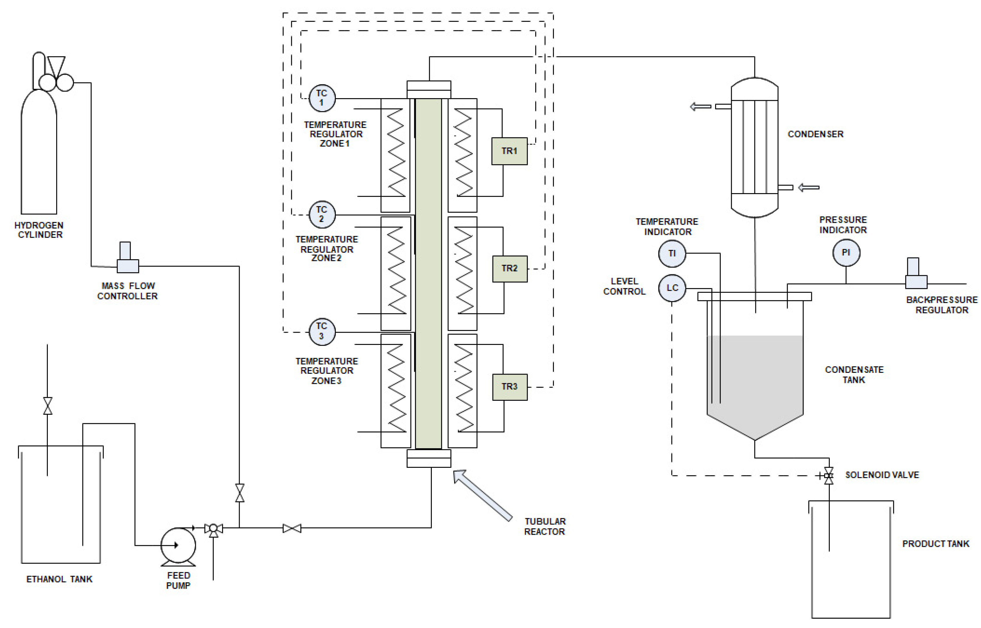
2.4. Laboratory and Pilot Chemical Plants

The ethanol dehydrogenation kinetic data, related to the previous section, have been collected in a laboratory chemical plant, as schematized in Figure 2 [42].
Recently, Semenov et al. [10] published a work describing the performance of a pilot plant working with a Cu-ZnO catalyst. A scheme of the employed pilot plant, containing 0.5 L of catalyst, is shown in Figure 3. The authors worked in a temperature range of 503–573 K and 1–20 atm. The best obtained results were 63% of ethanol conversion per pass and 94% of selectivity to ethyl acetate, together with very small amounts of side products such as butyl alcohol, butyl acetate, and ethyl butyrate. Moreover, the catalyst remained stable during all the time investigated in a long-term test (1250 h on stream).
However, considering the change of enthalpy passing from the dehydrogenation of acetaldehyde (endothermic) to the successive reaction of ethyl acetate formation (exothermic) it would be opportune, as before mentioned, to consider the reactor subdivided into two or three zones differently heated, as in the scheme of Figure 4.

2.5. Scale-Up: Scheme of the Industrial Plant and Most Opportune Operative Conditions

As mentioned before, an industrial process has been realized and commercialized by Davy Company in South Africa some years ago. The catalyst used by Davy for the ethanol dehydrogenation was a commercial copper chromite catalyst. A simplified scheme of their proposed plant is the one reported in Figure 5 taken from their private communication [43].
The step of selective hydrogenation is related to the hydrogenation of by-products of acetaldehyde condensation such as methyl ethyl ketone and butyraldehyde to obtain the corresponding alcohols that are easier to separate from ethyl acetate. Catalysts employed for this hydrogenation step were supported ruthenium or nickel. The molar conversion-per-passage of ethanol dehydrogenation was kept at 30–40% and selectivity to ethyl acetate was 90–96%. The relatively low selectivity to ethyl acetate justified the necessity of a supplementary hydrogenation step for an easier separation of the by-products. The dehydrogenation catalyst was pre-activated at 473–493 K in a stream containing 5% of hydrogen in nitrogen. The activated catalyst was then used at about 14 atm of pressure and 493–518 K of the temperature range. More recently, Eurochem Engineering has studied the same reaction and proposed the following simplified scheme for an industrial plant [24,42] (see Figure 6). An ethanol conversion per passage of 50–60% can normally be adopted and 5% of hydrogen is recycled acting as carrier gas and catalyst stabilizer. At least two distillation columns are needed to break the ethanol-ethyl acetate azeotrope and the purge is opportune to avoid side-products accumulation. The process scheme is simplified with respect to the one proposed by Davy because the copper-copper chromite catalyst employed by Eurochem Engineering was more selective and the amount of produced by-products was lower, thus not requiring their following hydrogenation and separation from the recycle stream. As before mentioned, this reaction system is singular because, looking at the reaction scheme, we can observe that ethanol transformation to ethyl acetate passes through the formation of acetaldehyde and this is an endothermic reaction (ΔH ≈ 71 kJ/mol), while the succeeding reaction is moderately exothermic (ΔH ≈ −40 kJ/mol). This means that the operation on both laboratory or pilot scale can be conducted in two ways: by using an approximately isotherm jacketed tubular reactor or by dividing the tubular reactor into two/three stages differently heated if the system should be maintained approximately isotherm.
At the industrial scale level, it is opportune to operate with three or four adiabatic reactors in sequence with a heat exchanger between a reactor and the successive stages to repristinate the desired reaction temperature. A preliminary estimation [42], based on the previously described copper chromite catalyst and related kinetic model, has been made using ChemCad software by simulating a complete industrial plant producing 21 tons/h of ethyl acetate and 1 ton/h of hydrogen. The overall process was divided into four different sections:
Section (1) was devoted to fresh ethanol purification and recycling. In this section, ethanol was dehydrated because water is dangerous for the catalyst. Dehydration was realized by distillation in the presence of ethylene glycol as an entrainer.
Section (2) Catalytic reactors. Dehydrated ethanol is heated, vaporized, and pressurized before entering the reactors. Four adiabatic reactors, each of 10 m3, were considered in sequence with inter-bed heating to compensate for the endothermicity of the reaction. The inlet temperature was 493 K for the first two reactors and 503 K for the other two.
Section (3) Hydrogen separation through two flash units. 5% of hydrogen is recycled acting as carrier gas and catalyst stabilizer.
Section (4) Separation of ethyl acetate from unreacted ethanol + by-products. To break the azeotrope ethanol-ethyl acetate a pressure swing distillation system has been considered by varying the pressure from 20 atm (the reaction pressure) to 1 atm. The separation scheme consists of a first distillation column working at 20 atm in which on the overhead the azeotrope ethyl acetate-ethanol was separated from pure ethyl acetate. The azeotropic mixture was then depressurized to 1 atm and fed to a second distillation column for further separation. Alternatively, the separation can be made by azeotropic distillation by using an effective agent such as ethyl ether, methyl formate, or cyclohexane [44] or some ionic liquids as entrainers [45].

2.6. Techno-Economic Analysis of the Process

A techno-economic analysis of this dehydrogenation process has recently been made by Khanhaeng et al. [16] with the scope of determining the cost of hydrogen produced through the steam reforming of ethanol and the ethanol dehydrogenation to acetaldehyde. The comparison has been performed by using Aspen PLUS V10. The hydrogen produced would be used for the synthesis of methanol by reacting hydrogen with CO2. This comparison is not useful for our purpose, but the cost estimation for ethanol dehydrogenation could be a useful reference for this study. The scheme of the industrial process considered by the authors is shown in Figure 7.
The kinetics published by Carotenuto et al. [28] have been used by Khanhaeng et al. for the calculations related to ethanol dehydrogenation. As reported in Figure 7, ethanol preheated at 493 K was pumped to 20 atm (E-200) by using high-pressure steam before entering in the fixed bed reactor (R-200). The conditions inside the reactor were maintained at 20 atm and 513 K. The reaction mixture (unreacted ethanol, ethyl acetate, and hydrogen) was cooled (E-202) at 308 K by cooling water. Unreacted ethanol and ethyl acetate were separated from hydrogen in a flash vessel (V-200). The hydrogen collected had a purity of 98.87%. The mixture of unreacted ethanol-ethyl acetate collected from the bottom stage was separated by extractive distillation using dimethylsulfoxide (DMSO) as suggested by Zhang et al. [46]. The extractive distillation occurred in a distillation column with 48 theoretical trays (T-200). 99.64% of ethyl acetate was separated with a purity of 99.5%. Then, the mixture of ethanol–DMSO was separated in a simple distillation column with 10 theoretical trays and the unreacted ethanol was then recycled. The authors evaluated the overall cost of the process consisting of Fixed Capital Investment + Cost of Manufacturing. The Fixed Capital Investment for a plant producing 1665 tons/year of hydrogen was estimated to be 4,784,141 USD, while the Cost of Manufacturing was calculated to be 6,919,315 USD/year. This cost also includes the value of the employed raw materials (ethanol 3,192,398 USD/year and DMSO 1924 USD/year) that must be calculated just for undergoing the first LOHC cycle, while, after the successive LOHC cycles the same ethanol is reused. Hence the effective cost of manufacturing would be: 6,919,315 − 3,192,398 − 1924 = 3,724,993 USD/year corresponding to a cost of 2237 USD/ton of hydrogen produced. The cost must be increased by considering the Fixed Capital Investment + Cost of Raw Materials for the start-up: 4,784,141 + 3,192,398 +1924 = 7,978,463 USD. If these expenses are amortized in 10 years we have a charge of 794,846 USD/year which is 479 USD/ton of hydrogen produced. Therefore, the estimation of the hydrogen cost will be 2237 + 479 = 2716 USD/ton of hydrogen produced. This means a cost of energy of about 0.0684 USD/kWh. However, we must point out that some energy must be supplied to the system for sustaining: (i) ethanol heating from room temperature to the reaction temperature, including the ethanol vaporization heat; (ii) the heat necessary for supplying the heat of the endothermic reaction; (iii) the energy necessary for the separations; (iv) the energy for ethanol recycle. This energy can be supplied by burning the purge that mainly contains ethanol with small amounts of acetaldehyde and very small amounts of other organic by-products. In this case, a moderate excess of ethanol must be employed in the process. An alternative could be the use of waste heat where available.
The different described behaviors suggest that there is a large margin for improvement in defining the best operative modality either increasing the catalyst activity or improving the operative conduct. We can now summarize some of the advantages of this process:
  • Only ethanol is required as feedstock. Then, if ethanol derives from a biological source the process is based on a renewable resource.
  • No problems of corrosion are envisaged during the plant operation. This allows using lower grades of material in the equipment fabrication and the plant costs are therefore reduced.
  • Pure hydrogen is obtained exempt from CO and CO2 and is therefore directly usable in fuel cells.
  • High purity of the product ethyl acetate (>99%), which can be directly sent to the second hydrogen reloading step without significant action.
In conclusion, starting from the described kinetic models, adapted to any newly developed catalyst, a more detailed process design can be obtained using ChemCAD or ASPEN. By imposing the desired productivity, a process optimization study can be realized with the aim of reducing the cost of plant realization and the cost of hydrogen production.

2.7. Process Intensification and Adoption of Membrane Reactors

An attempt to introduce process intensification has recently been made by the Startup Co. Greenyung [47,48,49,50,51,52], which published different patents proposing an innovative ethanol dehydrogenation process performed in a reactive distillation column, according to the following scheme (Figure 8).
In this case, ethanol is fed in a reactive distillation column, in which a dehydrogenation zone is present where the main reactions occur together with the associated side reactions. The employed catalyst was a physical mixture of CuO/Al2O3 and ZnO/Al2O3. Two streams exit from the reactor: (i) the produced hydrogen, which exits from the top of the column; (ii) the by-products, which are then hydrogenated because some side products are hard to separate from ethyl acetate. This means that the catalyst employed by Greenyung was not selective enough, but more details about this process and some data on costs are reported in a report of the Pennsylvania University available online [53] and on the published patents [47,48,49,50,51,52]. However, the idea of process intensification combining the dehydrogenation reaction with the hydrogen separation can be considered as a profitable opportunity. Another very promising possibility is the adoption of a membrane reactor as can be argued from the published literature [54,55,56,57,58,59]. The introduction of a membrane reactor allows the shifting of the equilibria of reactions (3) and (4) to the right by subtracting hydrogen from the chemical environment, so increasing the ethanol conversion at lower temperatures, without any loss in selectivity. Moreover, the use of a membrane reactor greatly simplifies the subsequent separation process that in this case occurs contemporarily with the reaction [13]. The dehydrogenation reaction of ethanol to acetaldehyde in membrane reactors has been studied by many authors [54,55,56,57] using particularly Pd and Pd-Ag membranes. More specifically the technology has been applied also to the ethanol dehydrogenation to ethyl acetate [58,59] using Pd, Pd-Ag and Pd-Zn membranes. As the dehydrogenation of ethanol to acetaldehyde is much faster than the ethanol-acetaldehyde coupling reaction, the residence time must be opportunely regulated to obtain the desired product. Moreover, in the presence of an opportune membrane, generated hydrogen can be selectively separated in situ from the reaction mixture and the reaction can be driven to completion. Moreover, reaction and hydrogen separation steps occur inside the same reactor, thus avoiding a further separation unit.

3. Ethyl Acetate Hydrogenation

3.1. Thermodynamics of the Occurring Reactions

Ethyl acetate hydrogenation is the reverse reaction of ethanol dehydrogenation. Therefore, we can write for the overall reaction:
C H 3 C O O C 2 H 5 + 2 H 2 2 C 2 H 5 O H
ΔH°500 K = −33.64 kJ/mol; ΔG°500 K = 6.44 kJ/mol Kp-500 = 0.21
This reaction very probably occurs in two steps that are:
( 1 )   C H 3 C O O C H 2 C H 3 + H 2 C H 3 C H O + C H 3 C H 2 O H
ΔH°500 K = 37.66 kJ/mol; ΔG°500 K = 17.03 kJ/mol
( 2 )   C H 3 C H O + H 2 C H 3 C H 2 O H
ΔH°500 K = −71.30 kJ/mol; ΔG°500 K = −10.59 kJ/mol
We have then Kp1-500 = 0.0166 and Kp2-500 = 12.76.
Calculations have been made on thermodynamic data reported by Stull et al. [36].

3.2. Catalysts Normally Employed for Promoting the Ethyl Acetate Hydrogenation Reaction

The interest in ethyl acetate hydrogenation to ethanol is due to the possibility to use ethanol as an alternative fuel and many papers have been published on the subject. Adkins and Folker [60] firstly described the reaction of esters hydrogenation promoted by a copper-chromium catalyst, being copper with chromium additive often used for fatty esters hydrogenation [61]. In fact, copper catalysts are highly active for C=O bond hydrogenation but much less active for C-C bond cleavage and this explains the choice of copper-based catalysts for ester hydrogenation. More recently, as chromium poses environmental problems, research is focused on the development of chromium-free catalysts. For this purpose, the addition to copper of other metal oxides, such as ZrO2, Fe2O3, or ZnO, has been investigated with the aim of promoting the activity of copper in the hydrogenation of esters to alcohols [62,63,64,65,66]. These works are of great interest for the LOHC process because very active catalysts in the hydrogenation of esters are probably also active in the reverse reaction of alcohol dehydrogenation. However, the hydrogenation of ethyl acetate to ethanol has received poor attention in the past and according to the few published works before 2014 a conversion of 40% of ethyl acetate with an ethanol selectivity of 80% has been reported [32]. In this article, a bimetallic Cu-Zn/SiO2 catalyst has been employed. The catalyst was obtained by calcination of the synthesized compound CuZn(OH)4(H2SiO3).2.4H2O at 473 K in air followed by a reduction step with hydrogen at 573 K. The Cu/Zn molar ratio of 1:1 was the optimal one leading to ethyl acetate conversion of 82% and ethanol selectivity of 94%. In another work [31], a Zn-promoted Cu-Al2O3 catalyst has been positively tested in a fixed bed reactor carried out at 523 K and 20 atm. The catalyst was prepared by impregnating alumina with a mixture of copper nitrate and zinc nitrate in a solution by incipient wetness. By opportunely regulating calcination and reduction conditions the best results were ethyl acetate conversion of 71.5% and ethanol selectivity of 95%. An activity test was prolonged for 90 h without any apparent catalyst deactivation. Interesting results have been obtained also by Di et al. [30] by using two different synthesized Cu/SiO2 catalysts. In the first case, an acidic copper nitrate solution was added to a basic sodium silicate solution obtaining a precipitate that was then calcined and reduced, thus providing the Cu/SiO2 catalyst. The other one was prepared by using the urea hydrolysis deposition-precipitation method. Catalytic runs were performed in a fixed bed reactor operating in the temperature range of 483–553 K at 30 atm using 1 g of catalyst and a LHSV = 1.24 h−1. The reactor was fed with a molar ratio H2/EA = 29. The best data obtained were 99.7% of ethyl acetate conversion and 99.07% of selectivity to ethanol. These data seem to be optimistic, probably because of the high H2/EA ratio. Good results have been obtained by Huang et al. [67] by using a Cu/SiO2 catalyst for hydrogenating methyl acetate to methanol + ethanol, obtaining a conversion of 94% and a selectivity of 94%. The catalyst was prepared by the precipitation-gel method by reacting copper nitrate with NaOH and then supporting the gel on silica. On the other hand, Lu et al. [33] prepared by coprecipitation and tested three different catalysts of the type Cu/ZnO/MOx, where MOx could be the supports SiO2, Al2O3, and ZrO2. The best catalyst results were from Cu/ZnO/Al2O3 that, in a fixed bed reactor (filled with 3 g of catalyst) kept at 553 K and 20 atm, gave a conversion of 80% with a selectivity of 95%. A value of the activation energy equal to 115 kJ/mol was estimated for this catalyst. This work can be reinterpreted for a kinetic approach to this reaction. A confirmation of the good performances of the CuZn-SiO2 catalyst has been furnished by Zhao et al. [68] who studied the hydrogenation of methyl acetate on the same catalyst. In conclusion, a catalyst active in the hydrogenation of ethyl acetate and probably also in the reverse reaction of ethanol dehydrogenation is a copper-based catalyst with copper extremely dispersed and hindered from sintering by the presence of other oxides. In this regard, the role of zinc as a promoter seems very important, while the support cannot be acidic to avoid the formation of by-products from the reactions of acetaldehyde condensation.

3.3. Ethyl Acetate Hydrogenation, Kinetic Methodology in Conventional Reactors

Very few papers have considered the kinetics of the ethyl acetate hydrogenation to ethanol on copper-based catalysts [69,70]. The first one determined the intrinsic kinetics of ethyl acetate hydrogenolysis to ethanol over a Cu-Zn/Al2O3 catalyst operating in a tubular reactor in the temperature range of 453–503 K, pressure 10–15 atm, LHSV 0.7–1.9 h−1 and molar ratio H2/EA = 20–50. A power law kinetic model was applied for interpreting the experimental data and the optimal kinetic parameters were determined by mathematical regression. The second paper studied the kinetic behavior in the ethyl acetate hydrogenation promoted by a Cu/ZrO2 catalyst prepared by coprecipitation from copper nitrate and zirconium oxynitrate with NaOH as precipitating agent. The kinetics of hydrogenation were studied at atmospheric pressure in the temperature range 293–513 K. The hydrogenation reaction was followed by gradually increasing the temperature from 293 to 513 K, stopping the temperature level for a determined time for evaluating conversion and yield at intermediate temperatures. The conversion varied therefore from 8 to 45%. The first ethyl acetate hydrogenation reaction was always far from the equilibrium, while acetaldehyde quickly reached the thermodynamic equilibrium. As a matter of fact, acetaldehyde hydrogenation is 6000 times more active than ethyl acetate hydrogenation. Data was collected on conversion as a function of the residence time, and hydrogenation rates as a function of the ratio H2/ester at different temperatures. The authors assumed the reaction mechanism suggested by Natal Santiago et al. [71], which is characterized by dissociative adsorption of ethyl acetate yielding acyl and alkoxy species:
C H 3 C O O C H 2 C H 3 + 2 C H 3 C O + C H 3 C H 2 O
The alkoxy fragment is rapidly hydrogenated to ethanol, whilst the acyl fragment is less reactive and, more slowly, can be partially hydrogenated to acetaldehyde or fully hydrogenated to ethanol. A moderate deactivation was observed due to coke deposition occurring at higher temperatures. This phenomenon is hindered by operating in the presence of an excess of hydrogen. A kinetic model is mentioned in the work by using, for the overall reaction, a power law kinetic expression. Reaction order results were 0.1–0.3 for hydrogen and −0.4 to 0.1 for ethyl acetate; the apparent activation energy was 74 kJ/mol.
An example of a laboratory-scale plant (Figure 9) is reported by the already cited Zhu et al. [31].
Another example is the one reported by Jiang et al. (see Figure 10) [69].
Based on these data, it could be possible to elaborate a simplified scheme for the corresponding industrial plant.

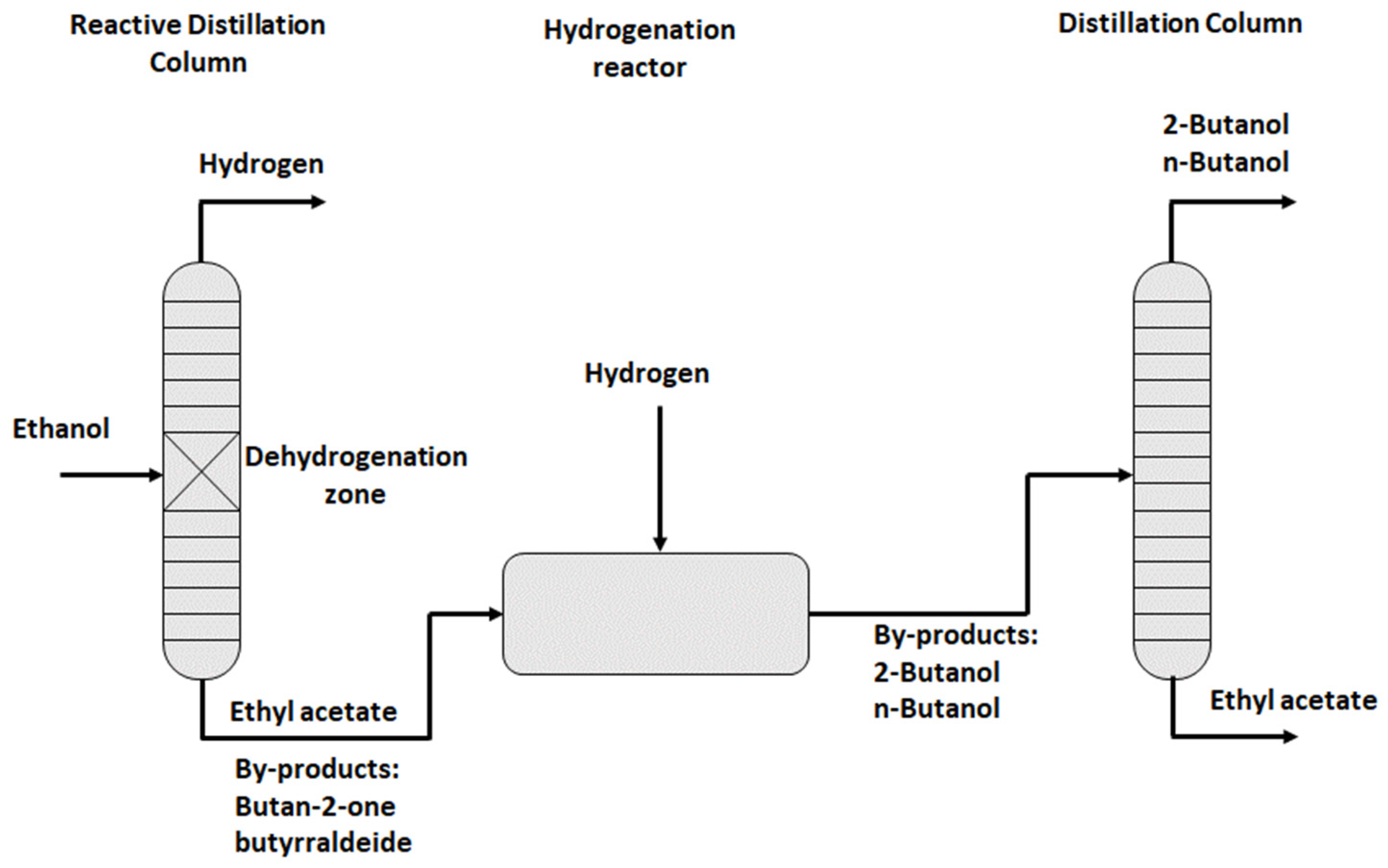
3.4. The Industrial Ethanol-Ethylacetate LOHC Process

A work published very recently by Mevawala et al. [35] has specifically been devoted to the possibility of using the ethanol-ethyl acetate system as a LOHC by examining three different aspects: the thermodynamics of the chemical reaction, the energy balance of the process and the assessment of greenhouse gas emission. This work confirmed that the energy demand for dehydrogenation is small, and the authors calculated an energy efficiency of the system equal to 88%. The results obtained by the authors show that the ethanol-ethyl acetate system is very promising as a LOHC and is worth further study. In particular, the same authors furnished a complete Block Flow Diagram developed in Aspen Plus 10 of the ethanol-ethyl acetate LOHC process for a production of 500 kg/h of hydrogen.

4. Ethanol as a Possible LOHC in Comparison with Other Candidate Molecules

“Green” electricity provided by renewable sources of energy such as photovoltaic plants, wind turbines, hydroelectric plants, geothermal energy plants, and energy from biomass can be used within an electrolysis process to produce gaseous hydrogen from water. However, when the renewable sources of energy are in places where the energy demand is low, it is opportune to store the excess of produced energy. This can be done by producing hydrogen and storing it inside a LOHC through a hydrogenation reaction. The hydrogenated molecule must allow long-term storage, must be suitable for long-distance transport and must be ready, at the time of need, to unload hydrogen after the transport and storage in a place where the energy demand is high. Many different LOHC substances have been proposed until now such as: methylcyclohexane, 12H-N-ethylcarbazole, 18H dibenzyl toluene, naphthalene and others. The use of a LOHC is based on a two steps cycle: (i) loading hydrogen into the LOHC molecule through hydrogenation; (ii) recovering hydrogen through dehydrogenation. Normally, hydrogenation is an exothermic process, and the reaction heat can be used to keep the reaction pressure and temperature at the desired level. In contrast, dehydrogenation is an endothermic process occurring at low pressure and high temperatures. The hydrogen released by dehydrogenation requires, therefore, heat from an appropriate heat source to drive the dehydrogenation process. This occurs when LOHCs are molecules containing aromatic rings. The heat necessary during dehydrogenation can be furnished by burning part of the hydrogen produced, so reducing the efficiency of the overall process, or alternatively by building the plant near a waste heat source. Let us consider, for this purpose, the LOHC system methylcyclohexane-toluene as a reference for comparison [72]. The use of bioethanol as LOHC allows storing of 4.3% by weight of hydrogen, which means storage of 34 kg of H2/m3 of ethanol or, alternatively, 1.35 kWh/L of ethanol. Bioethanol is a free-flowing liquid that has the advantage of being non-toxic, renewable, biodegradable, and largely available as raw material at a lower and lower cost. Bioethanol is, therefore, a good LOHC candidate for the application of green energy storage according to the cycle of Figure 11.
Ethyl acetate can also be considered a green product and, like ethanol, benign for both the environment and human safety. To compare the cost of using ethanol as LOHC with respect to other compounds, we can neglect the cost of transportation, this being similar for all the liquid organic compounds; therefore, the comparison will be made on the cost of the dehydrogenation-hydrogenation cyclic operations. Let us consider, for this purpose, one of the most studied LOHCs, namely, methylcyclohexane (MCH). The MCH-toluene reaction is promoted by catalysts of platinum or nickel supported on alumina, at 623–723 K, with a yield between 50 and 92%. The highest hydrogen yield (95% at 593 K) was obtained on a K-Pt/Al2O3 catalyst [15]. MCH has a hydrogen storage capacity of 6.11% by weight, which means density storage of 47.5 kg of H2/m3.
Despite the advantage in the storage capacity of MCH with respect to ethanol, the energy that must be consumed in the MCH dehydrogenation favors the use of ethanol. The overall reaction enthalpy for the reaction has already been seen:
2 C 2 H 5 O H C H 3 C O O C 2 H 5 + 2 H 2
ΔH°500 K = 33.64 kJ/mol.
This value is much lower than that of MCH and the reaction temperature range, between 493–543 K, is lower, too:
Methylcyclohexane Toluene + 3 H 2
ΔH°500 K = 213.22 kJ/mol.
Moreover, the drawback of the higher endothermicity of the dehydrogenation of MCH respect to that of ethanol is more evident considering the enthalpies calculated per moles of produced hydrogen. In fact, although the dehydrogenation of ethanol leads to the formation of two moles of hydrogen whilst three moles are produced from the dehydrogenation of MCH, the enthalpy per mole of produced hydrogen is markedly lower in the first case, being 16.82 kJ/mol instead of 71.11 kJ/mol, thus confirming that the dehydrogenation reaction of MCH requires a higher amount of heat than that of ethanol. The heat can be provided in several ways, e.g., from the combustion of compounds external to the process or, more advantageously, from the combustion of a part of the produced hydrogen. In fact, the enthalpy of hydrogen combustion is about 243 kJ/mol thus, being comparable with the enthalpy of the MCH-toluene reaction (213.22 kJ/mol), about one mole of hydrogen produced could be used to sustain the dehydrogenation reaction of MCH. However, this strategy lowers the effective hydrogen storage to about 5%, which becomes comparable with the level for ethanol. Hydrogen release from ethanol is achieved at lower temperatures and with significantly less energy consumption. Moreover, hydrogenation, in this case, is just moderately exothermic, while, for MCH we have a highly exothermic reaction with problems of heat transfer. Besides, MCH dehydrogenation, considering its high endothermicity, requires a more sophisticated reactor characterized by very high heat exchange efficiency. An opposite situation characterizes the hydrogenation reaction that being very exothermic requires a very efficient heat exchange system. This means additional costs for the plant realization.
The mentioned advantages of ethanol as LOHC can be further implemented by increasing the dehydrogenation reaction rate and the overall reaction yield. This can be done by improving the catalyst performance and by employing membrane reactors. The catalyst activity is strongly related to the specific surface area of dispersed copper while selectivity and stability depend on the copper chemical environment. The improvement of catalyst performance in terms of activity and selectivity is therefore of paramount importance for the overall efficiency of the process.
As previously mentioned, the introduction of a membrane reactor allows the shifting of the equilibrium to the right by subtracting hydrogen from the chemical environment, so increasing the ethanol conversion at lower temperatures, without any loss in selectivity. The introduction of a suitable membrane reactor requires a study oriented to the specific case to evaluate the best membrane to be used and the most opportune operative conditions. On the other hand, many studies have been published on hydrogen separation for similar purposes such as, for example, in the case of ethanol and methanol steam reforming [73,74].

5. Conclusions

The potential impact of the employment of ethanol as a hydrogen carrier through the chemical cycle dehydrogenation-hydrogenation can be summarized in the following points:
(a)
The realization of an innovative and simple system for hydrogen storage and transportation.
(b)
The use of inexpensive raw materials (bio-ethanol, ethyl acetate), which are abundant, renewable, biodegradable, non-toxic, and not dangerous for the environment.
(c)
The synthesis of more active and selective dehydrogenation-hydrogenation catalysts and the development of techniques for their characterization and kinetic testing.
(d)
The realization and modeling of membrane reactors for process intensification.
(e)
Modeling of the overall cyclic system for different operative scales.
Significant progress in each of the mentioned points would render feasible and convenient the process by overcoming all the disadvantages in the use of the system ethanol-ethyl acetate as LOHC with respect to the more conventional systems.

Author Contributions

Conceptualization, E.S.; data curation, E.S. and R.T.; writing—original draft preparation, E.S.; writing—review and editing, E.S., R.T., S.F. and A.M.R.G.; supervision, E.S. and A.M.R.G. All authors have read and agreed to the published version of the manuscript.

Funding

This research received no external funding.

Data Availability Statement

No new data were created or analyzed in this study. Data sharing is not applicable to this article.

Acknowledgments

Eurochem Engineering is acknowledged for the financial support. Thanks are due also to Giuseppina Carotenuto for some useful information reported in her PhD thesis.

Conflicts of Interest

The authors declare no conflict of interest.

References

  1. OECD/Food and Agriculture Organization of the United Nations. Biofuels. In OECD-FAO Agricultural Outlook 2022–2031; OECD Publishing: Paris, France, 2022; pp. 232–243. [Google Scholar] [CrossRef]
  2. Iwasa, N.; Takezawa, N. Reforming of ethanol—Dehydrogenation to ethyl acetate and steam reforming to acetic acid over copper-based catalysts. Bull. Chem. Soc. Jpn. 1991, 64, 2619–2623. [Google Scholar] [CrossRef]
  3. Tu, Y.I.; Chen, Y.W.; Li, C. Characterization of unsupported copper-chromium catalysts for ethanol dehydrogenation. J. Mol. Catal. 1994, 89, 179–189. [Google Scholar] [CrossRef]
  4. Wu, R.; Sun, K.; Chen, Y.; Zhang, M.; Wang, L. Ethanol dimerization to Ethyl acetate and hydrogen on the multifaceted copper catalysts. Surface Sci. 2021, 703, 121742. [Google Scholar] [CrossRef]
  5. Inui, K.; Kurabayashi, T.; Sato, S. Direct synthesis of ethyl acetate from ethanol over Cu-Zn-Zr-Al-O catalyst. Appl. Catal. A Gen. 2002, 237, 53–61. [Google Scholar] [CrossRef]
  6. Inui, K.; Kurabayashi, T.; Sato, S. Direct synthesis of ethyl acetate from ethanol carried out under pressure. J. Catal. 2002, 212, 207–215. [Google Scholar] [CrossRef]
  7. Inui, K.; Kurabayashi, T.; Sato, S.; Ichikawa, N. Effective formation of ethyl acetate from ethanol over Cu-Zn-Zr-Al-O catalyst. J. Mol. Catal. A Chem. 2004, 216, 147–156. [Google Scholar] [CrossRef]
  8. Colley, S.W.; Tabatabaei, J.; Waugh, K.C.; Wood, M.A. The detailed kinetics and mechanism of ethyl ethanoate synthesis over a Cu/Cr2O3 catalyst. J. Catal. 2005, 236, 21–33. [Google Scholar] [CrossRef]
  9. Gaspar, A.B.; Barbosa, F.G.; Letichevsky, S.; Appel, L.G. The one-pot ethyl acetate syntheses: The role of the support in the oxidative and the dehydrogenative routes. Appl. Catal. A Gen. 2010, 380, 113–117. [Google Scholar] [CrossRef]
  10. Semenov, I.P.; Men’shchikov, V.A.; Sycheva, O.I. Pilot tests of a catalyst for the production of ethyl acetate from ethanol. Catal. Ind. 2020, 12, 287–291. [Google Scholar] [CrossRef]
  11. Usman, M.R. Hydrogen storage methods: Review and current status. Renew. Sustain. Energy Rev. 2022, 167, 112743. [Google Scholar] [CrossRef]
  12. Phung, T.K. Copper-based catalysts for ethanol dehydrogenation and dehydrogenative coupling into hydrogen, acetaldehyde and ethyl acetate. Int. J. Hydrogen Energy 2022, 47, 42234–42249. [Google Scholar] [CrossRef]
  13. Sekine, Y.; Higo, T. Recent trends on the dehydrogenation catalysis of liquid organic hydrogen carrier (LOHC): A review. Top. Catal. 2021, 64, 470–480. [Google Scholar] [CrossRef]
  14. Rao, P.C.; Yoon, M. Potential liquid-organic hydrogen carrier (LOHC) systems: A review on recent progress. Energies 2020, 13, 6040. [Google Scholar] [CrossRef]
  15. Niermann, M.; Beckendorff, A.; Kaltschmitt, M.; Bonhoff, K. Liquid organic hydrogen carrier (LOHC)—Assessment based on chemical and economic properties. Int. J. Hydrogen Energy 2019, 44, 6631–6654. [Google Scholar] [CrossRef]
  16. Khamhaeng, P.; Laosiripojana, N.; Assabumrungrat, S.; Kim-Lohsoontorn, P. Techno-economic analysis of hydrogen production from dehydrogenation and steam reforming of ethanol for carbon dioxide conversion to methanol. Int. J. Hydrogen Energy 2021, 46, 30891–30902. [Google Scholar] [CrossRef]
  17. Bueno, J. Copper-Based Catalysts, Process for Preparing Same and Use Thereof. WO2004/080589 A2, 12 March 2004. [Google Scholar]
  18. Inui, K.K.; Takahashi, T.S.; Kurabayashi, T.I. Catalyst for Ester Production and Process for Producing Ester. U.S. Patent 2004/0242917 A1, 2 December 2004. [Google Scholar]
  19. Inui, K.K.; Takahashi, T.S.; Kurabayashi, T.I. Catalyst for Ester Production and Process for Producing Ester. U.S. Patent 7,091,155 B2, 15 August 2006. [Google Scholar]
  20. Colley, S.W.; Fawcett, C.R.; Sharif, M.; Tuck, M.W.M.; Watson, D.J.; Wood, M.A. Davy Process Tech., Republic of South Africa. Purification of Ethyl Acetate from Mixture Comprising Ethanol and Water by Pressure Swing Distillation. EP 1 117 629 B1, 15 December 2004. [Google Scholar]
  21. Colley, S.W.; Fawcett, C.R.; Rathmell, C.; Tuck, M.W.M. Process for the Preparation of Ethyl Acetate. EP 1 117 631 B1, 17 November 2004. [Google Scholar]
  22. Colley, S.W.; Fawcett, C.R.; Sharif, M.; Tuck, M.W.M.; Watson, D.J.; Wood, M.A. Process. U.S. Patent 7,553,397 B1, 30 June 2009. [Google Scholar]
  23. Santacesaria, E.; Di Serio, M.; Tesser, R.; Carotenuto, G. Process for the Production of Ethyl Acetate from Ethanol. WO2011/104738A2, 1 September 2011. [Google Scholar]
  24. Santacesaria, E.; Carotenuto, G.; Tesser, R.; Di Serio, M. Ethanol dehydrogenation to ethyl acetate by using copper and copper chromite catalysts. Chem. Eng. J. 2012, 179, 209–220. [Google Scholar] [CrossRef]
  25. Carotenuto, G.; Tesser, R.; Di Serio, M.; Santacesaria, E. Bioethanol as feedstock for chemicals such as acetaldehyde, ethyl acetate and pure hydrogen. Biomass Conv. Bioref. 2013, 3, 55–67. [Google Scholar] [CrossRef] [Green Version]
  26. Santacesaria, E.; Carotenuto, G.; Tesser, R.; Di Serio, M. Production of pure hydrogen by ethanol dehydrogenation. Oil Gas Eur. Mag. 2011, 37, 99–102. [Google Scholar]
  27. Santacesaria, E.; Carotenuto, G.; Tesser, R.; Di Serio, M. Production of pure hydrogen by ethanol dehydrogenation. In Proceedings of the DGMK Conference, Berlin, Germany, 4–6 October 2010. [Google Scholar]
  28. Carotenuto, G.; Tesser, R.; Di Serio, M.; Santacesaria, E. Kinetic study of ethanol dehydrogenation to ethyl acetate promoted by a copper/copper chromite catalyst. Catal. Today 2013, 203, 202–210. [Google Scholar] [CrossRef]
  29. Luo, M.; Das, T.K.; Delibas, C.; Davis, B.H. Heterogeneous catalytic hydrogenation of ethyl acetate to produce ethanol. Top. Catal. 2014, 57, 757–761. [Google Scholar] [CrossRef]
  30. Di, W.; Cheng, J.; Tian, S.; Li, J.; Chen, J.; Sun, Q. Synthesis and characterization of supported copper phyllosilicate catalysts for acetic ester hydrogenation to ethanol. Appl. Catal. A Gen. 2016, 510, 244–259. [Google Scholar] [CrossRef]
  31. Zhu, Y.; Shi, L. Zn promoted Cu–Al catalyst for hydrogenation of ethyl acetate to alcohol. J. Ind. Eng. Chem. 2014, 20, 2341–2347. [Google Scholar] [CrossRef]
  32. Zhu, Y.; Shi, X.W.L. Hydrogenation of ethyl acetate to ethanol over bimetallic Cu-Zn/SiO2 catalysts prepared by means of coprecipitation. Bull. Korean Chem. Soc. 2014, 35, 141–146. [Google Scholar] [CrossRef] [Green Version]
  33. Lu, Z.; Yin, H.; Wang, A.; Hu, J.; Xue, W.; Yin, H.; Liu, S. Hydrogenation of ethyl acetate to ethanol over Cu/ZnO/MOx (MOx = SiO2, Al2O3, and ZrO2) catalysts. J. Ind. Eng. Chem. 2016, 37, 208–215. [Google Scholar] [CrossRef]
  34. Tran, B.L.; Johnson, S.I.; Brooks, K.P.; Autrey, S.T. Ethanol as a liquid organic hydrogen carrier for seasonal microgrid application: Catalysis, theory, and engineering feasibility. ACS Sustain. Chem. Eng. 2021, 9, 7130–7138. [Google Scholar] [CrossRef]
  35. Mevawala, C.; Brooks, K.; Bowden, M.E.; Breunig, H.M.; Tran, B.L.; Gutiérrez, O.Y.; Autrey, T.; Müller, K. The ethanol–ethyl acetate system as a biogenic hydrogen carrier. Energy Technol. 2022, 11, 2200892. [Google Scholar] [CrossRef]
  36. Stull, D.R.; Vestrum, E.F.; Sinke, G.C. The Chemical Thermodynamics of Organic Compounds, 1st ed.; John Wiley: New York, NY, USA, 1969. [Google Scholar]
  37. Finger, P.H.; Osmari, T.A.; Costa, M.S.; Bueno, J.M.C.; Gallo, J.M.R. The role of the interface between Cu and metal oxides in the ethanol dehydrogenation. Appl. Catal. A Gen. 2020, 589, 117236. [Google Scholar] [CrossRef]
  38. Pang, J.; Zheng, M.; Wang, C.; Liu, H.; Liu, X.; Sun, J.; Wang, Y.; Zhang, T. Hierarchical echinus-like Cu-MFI catalysts for ethanol dehydrogenation. ACS Catal. 2020, 10, 13624–13629. [Google Scholar] [CrossRef]
  39. Freitas, I.C.; Damyanova, S.; Oliveira, D.C.; Marquez, C.M.P.; Bueno, J.M.C. Effect of Cu content on the surface and catalytic properties of Cu/ZrO2 catalyst for ethanol dehydrogenation. J. Mol. Catal. A Chem. 2014, 381, 26–37. [Google Scholar] [CrossRef]
  40. Tu, Y.J.; Li, C.; Chen, Y.W. Effect of chromium promoter on copper catalysts in ethanol dehydrogenation. J. Chem. Technol. Biotechnol. 1994, 59, 141–147. [Google Scholar] [CrossRef]
  41. Men’shchikov, V.A.; Gol’dshtein, L.K.; Semenov, I.P. Kinetics of ethanol dehydrogenation into ethyl acetate. Kinet. Catal. 2014, 55, 12–17. [Google Scholar] [CrossRef]
  42. Carotenuto, G. Innovative Processes for the Production of Acetaldehyde, Ethyl Acetate and Pure Hydrogen by Ethanol. Ph.D. Thesis in Chemistry Macromolecular and Catalysis, University of Naples Federico II, Naples, Italy, November 2011. [Google Scholar]
  43. Private Communication: Davy Process Technology Report; Ethyl Acetate Process. 13 April 2004.
  44. Berg, L. Separation of Ethyl Acetate from Ethanol by Azeotropic Distillation. U.S. Patent 5,993,610 A, 30 November 1999. [Google Scholar]
  45. Zhu, Z.; Ri, Y.; Jia, H.; Wang, Y.; Wang, Y. Process evaluation on the separation of ethyl acetate ethanol using extractive distillation with ionic liquid. Sep. Purif. Technol. 2017, 181, 44–52. [Google Scholar] [CrossRef]
  46. Zhang, Q.; Liu, M.; Li, C.; Zeng, A. Design and control of extractive distillation process for separation of the minimum-boiling azeotrope ethyl-acetate and ethanol. Chem. Eng. Res. Des. 2018, 136, 57–70. [Google Scholar] [CrossRef]
  47. Gadewar, S.B. Ethyl Acetate Production. U.S. Patent 2012/0035390A1, 9 February 2012. [Google Scholar]
  48. Gadewar, S.B.; Vicente, B.C.; Norton, R.E.; Doherty, M.F. Ethyl Acetate Production. U.S. Patent 2013/0197266A1, 1 August 2013. [Google Scholar]
  49. Gadewar, S.B. Ethyl Acetate Production. U.S. Patent 8,562,921B2, 22 October 2013. [Google Scholar]
  50. Gadewar, S.B.; Stoimenov, P.K. Ethyl Acetate Production. U.S. Patent 2014/0012037A1, 9 January 2014. [Google Scholar]
  51. Gadewar, S.B.; Vicente, B.C.; Norton, R.E.; Doherty, M.F. Ethyl Acetate Production. U.S. Patent 9,079,851B2, 14 July 2015. [Google Scholar]
  52. Gadewar, S.B.; Stoimenov, P.K. Ethyl Acetate Production. U.S. Patent 9,447,018B2, 20 September 2016. [Google Scholar]
  53. Senior Design Reports of the University of Pennsylvania: Ethanol to Ethyl Acetate. Available online: https://core.ac.uk/download/pdf/219382692.pdf (accessed on 27 January 2023).
  54. Raich, B.A.; Foley, H.C. Ethanol dehydrogenation with a palladium membrane reactor: An alternative to Wacker chemistry. Ind. Eng. Chem. Res. 1998, 37, 3888–3895. [Google Scholar] [CrossRef]
  55. Keuler, J.N.; Lorenzen, L. Pd-Ag membranes and their application for dehydrogenation of ethanol in a membrane reactor. In Proceedings of the 221st National Meeting ACS, San Diego, CA, USA, 1–5 April 2001. [Google Scholar]
  56. Keuler, J.N.; Lorenzen, L. Comparing and modeling the dehydrogenation of ethanol in a plug-flow reactor and a Pd-Ag membrane reactor. Ind. Eng. Chem. Res. 2002, 41, 1960–1966. [Google Scholar] [CrossRef]
  57. Lin, W.H.; Chang, H.F. A study of ethanol dehydrogenation reaction in a palladium membrane reactor. Catal. Today 2004, 97, 181–188. [Google Scholar] [CrossRef]
  58. Sánchez, A.B.; Homs, N.; Miachon, S.; Dalmon, J.A.; Fierro, J.L.G.; de la Piscina, P.R. Direct transformation of ethanol into ethyl acetate through catalytic membranes containing Pd or Pd-Zn: Comparison with conventional supported catalysts. Green Chem. 2011, 13, 2569–2575. [Google Scholar] [CrossRef]
  59. Zeng, G.; Chen, T.; He, L.; Pinnau, I.; Lai, Z.; Huang, K.W. A green approach to ethyl acetate: Quantitative conversion of ethanol through direct dehydrogenation in a Pd-Ag membrane reactor. Chem. Eur. J. 2012, 18, 15940–15943. [Google Scholar] [CrossRef]
  60. Adkins, H.; Folkers, K. The catalytic hydrogenation of esters to alcohols. J. Am. Chem. Soc. 1931, 53, 1095–1097. [Google Scholar] [CrossRef]
  61. Thakur, D.S.; Carrick, W. Copper Chromite Hydrogenation Catalysts for Production of Fatty Alcohols. WO 2012/074841, 7 June 2012. [Google Scholar]
  62. Yuan, P.; Liu, Z.Y.; Zhang, W.; Sun, H.; Liu, S. Cu-Zn/Al2O3 catalyst for the hydrogenation of esters to alcohols. Chin. J. Catal. 2010, 31, 769–775. [Google Scholar] [CrossRef]
  63. He, L.; Cheng, H.; Liang, G.; Yu, Y.; Zhao, F. Effect of structure of CuO/ZnO/Al2O3 composites on catalytic performance for hydrogenation of fatty acid ester. Appl. Catal. A Gen. 2013, 452, 88–93. [Google Scholar] [CrossRef]
  64. Huang, H.; Cao, G.; Wang, S. An evaluation of alkylthiols and dialkyl disulfides on deactivation of Cu/Zn catalyst in hydrogenation of dodecyl methyl ester to dodecanol. J. Ind. Eng. Chem. 2014, 20, 988–993. [Google Scholar] [CrossRef]
  65. Brands, D.S.; Poels, E.K.; Bliek, A. Ester hydrogenolysis over promoted Cu/SiO2 catalysts. Appl. Catal. A Gen. 1999, 184, 279–289. [Google Scholar] [CrossRef]
  66. Kim, S.M.; Lee, M.E.; Choi, J.W.; Suh, D.J.; Suh, Y.W. Role of ZnO in Cu/ZnO/Al2O3 catalyst for hydrogenolysis of butyl butyrate. Catal. Commun. 2011, 12, 1328–1332. [Google Scholar] [CrossRef]
  67. Huang, X.; Ma, M.; Miao, S.; Zheng, Y.; Chen, M.; Shen, W. Hydrogenation of methyl acetate to ethanol over a highly stable Cu/SiO2 catalyst: Reaction mechanism and structural evolution. Appl. Catal. A Gen. 2017, 531, 79–88. [Google Scholar] [CrossRef]
  68. Zhao, Y.; Shan, B.; Wang, Y.; Zhou, J.; Wang, S.; Ma, X. An effective CuZn-SiO2 bimetallic catalyst prepared by hydrolysis precipitation method for the hydrogenation of methyl acetate to ethanol. Ind. Eng. Chem. Res. 2018, 57, 4526–4534. [Google Scholar] [CrossRef]
  69. Jiang, X.C.; Wang, Z.G.; Li, C.X. Intrinsic kinetics of ethyl acetate hydrogenolysis to ethanol over a Cu-Zn/Al2O3 catalyst. J. Beijing Univ. Chem. Technol. 2014, 41, 36–39. [Google Scholar]
  70. Schittkowski, J.; Tölle, K.; Anke, S.; Stürmer, S.; Muhler, M. On the bifunctional nature of Cu/ZrO2 catalysts applied in the hydrogenation of ethyl acetate. J. Catal. 2017, 352, 120–129. [Google Scholar] [CrossRef]
  71. Natal Santiago, M.A.; Sánchez-Castillo, M.A.; Cortight, R.D.; Dumesic, J.A. Catalytic reduction of acetic acid, methyl acetate, and ethyl acetate over silica-supported copper. J. Catal. 2000, 193, 16–28. [Google Scholar] [CrossRef]
  72. Niermann, M.; Drünert, S.; Kaltschmitt, M.; Bonhoff, K. Liquid organic hydrogen carriers (LOHCs)–techno-economic analysis of LOHCs in a defined process chain. Energy Environ. Sci. 2019, 12, 290–307. [Google Scholar] [CrossRef]
  73. Gallucci, F.; Basile, A. Pd-Ag membrane reactor for steam reforming reactions: A comparison between different fuels. Int. J. Hydrogen Energy 2008, 33, 1671–1687. [Google Scholar] [CrossRef]
  74. Rahimpour, M.R.; Samimi, F.; Babapoor, A.; Tohidian, T.; Mohebi, S. Palladium membranes applications in reaction systems for hydrogen separation and purification: A review. Chem. Eng. Process. 2017, 121, 24–49. [Google Scholar] [CrossRef]
Scheme 1. Pathways of by-products formation from acetaldehyde condensation.
Processes 11 00785 sch001
Figure 1. Kinetic behavior of copper-copper-chromite catalyst. Ethanol conversion and selectivities to respectively ethyl acetate and acetaldehyde, for different contact times at 493 K and 20 atm. Curves have been obtained by solving the system of differential Equations (10)–(13) with the parameters of Table 1.
Processes 11 00785 g001
Figure 2. A1—Ethanol tank; A2—HPLC pump; A3, A5—Check valves; A4—relief valve; A6—Flow mass controller, A7—Cylinder containing a mixture of hydrogen 5% and nitrogen; A8—pre-heater to vaporize ethanol; A9—Stainless steel packed bed tubular reactor. A10—Back pressure regulator; A11—Heat exchanger; A13, A14—Product tanks raising; A12/A15—Liquid nitrogen dewars; S1/S2/S5—Temperature probes; S3/S4—Pressure transducers. The reactor A9 was heated by two independently thermoregulated heaters.
Processes 11 00785 g002
Figure 3. Scheme of a pilot plant, containing 0.5 L of catalyst, used by Semenov et al. to verify catalyst stability in runs prolonged for 1250 h. (1) Raw material container; (2) Dosing pump; (3) Tubular fixed bed reactor; (4) Heating furnace; (5) Pressure gauge; (6) Movable thermocouple; (7) Temperature reading; (8) and (9) Temperature regulation system; (10) Ethyl acetate, ethanol condenser; (11)–(13) Hydrogen flow measurement; (15) Container to collect liquid produced; (16) Hydrogen bottle; (17) Pressure reducer; (18) valve.
Processes 11 00785 g003
Figure 4. An example of the pilot plant suggested by the authors.
Processes 11 00785 g004
Figure 5. Simplified scheme of the DAVY process for ethanol dehydrogenation [43].
Processes 11 00785 g005
Figure 6. Simplified scheme of the Eurochem process for ethanol dehydrogenation. Employed catalyst CuCrO4/CuO/Cu/BaCrO4/Al2O3 [42].
Processes 11 00785 g006
Figure 7. Scheme of an industrial plant of ethanol dehydrogenation to ethyl acetate. Plant capacity was calibrated for producing 1665 tons/year of hydrogen with an ethanol feed of 38,700 tons/year. Re-elaborated from [16] and reported with the permission of Elsevier.
Processes 11 00785 g007
Figure 8. Simplified scheme of the Greenyung Process.
Processes 11 00785 g008
Figure 9. Fixed-bed reaction system. 1—H2; 2—N2; 3—Reducing valve; 4—Valve; 5—Mass flow meter; 6—Three way valve; 7—Pressure gauge; 8—Reactor; 9—Heater; 10—Thermocouple; 11—Temperature controller; 12—Condenser; 13—Gas-liquid separator; 14—Back pressure valve; 15—Gas washing bottle; 16—Micro syringe pump; 17—Raw materials. See ref. [31]. Reported with the permission of Elsevier.
Processes 11 00785 g009
Figure 10. 1—Ethyl acetate reservoir; 2—Hydrogen bottle; 3—Pump; 4—Pressure gauge; 5—Valves; 6—Pressure reducer; 7—Non-return valve; 8—Tubular reactor; 9—Heating furnace; 10–11—Thermocouples and thermoregulators; 12—Liquid condenser; 13—Liquid product container; 14—Valve; 15,16—Valves; 17—Gas Chromatograph;18—Hydrogen to the vent. See Ref. [69].
Processes 11 00785 g010
Figure 11. Overview of coupling ethanol dehydrogenation and ethyl acetate hydrogenation of ethyl acetate to ethanol with the scope of storing hydrogen inside the ethanol molecule and transporting it to a place of final use.
Processes 11 00785 g011
Table 1. Optimized kinetic parameters obtained for a commercial copper-copper chromite catalyst, from [28], reported with the permission of Elsevier.
Kinetic ConstantsActivation Energy (kJ/mol)
k1-493K97.1 ± 6.8(mol/(gcat·h·atm))151.67 ± 18.20
k2-493K0.089 ± 9.8 × 10⁻³ (mol/(gcat·h·atm2))54.18 ± 2.72
k3-493K0.0011 ± 7.8 × 10⁻⁴ (mol/(gcat·h·atm2))6.69 × 10−4 ± 7.53 × 10⁻⁵
Adsorption parameters (atm−1)Adsorption Enthalpy (kJ/mol)
bEtOH-493K10.4 ± 0.83−106.82 ± 10.67
bAcH-493K98.4 ± 12.79−29.37 ± 1.46
bEA-493K41.2 ± 4.94−58.20 ± 0.59
bH-493K2.5 × 10−4 ± 3.5 × 10⁻⁵−55.81 ± 6.15
Disclaimer/Publisher’s Note: The statements, opinions and data contained in all publications are solely those of the individual author(s) and contributor(s) and not of MDPI and/or the editor(s). MDPI and/or the editor(s) disclaim responsibility for any injury to people or property resulting from any ideas, methods, instructions or products referred to in the content.

