Article

Dynamic Analysis of the Lifting Arm System in the Integrated Offshore Platform Decommissioning Equipment in Complicated Sea States

College of Mechanical and Electronic Engineering, China University of Petroleum (East China), Qingdao 266580, China
*
Author to whom correspondence should be addressed.
Processes 2023, 11(2), 645; https://doi.org/10.3390/pr11020645
Submission received: 13 January 2023 / Revised: 10 February 2023 / Accepted: 11 February 2023 / Published: 20 February 2023
(This article belongs to the Special Issue Risk Assessment and Reliability Engineering of Process Operations)

Abstract

:
With the further exploitation of offshore resources, there are more and more offshore oil and gas fields which cannot meet the production capacity requirements. So, it becomes extremely urgent to pay attention to the decommissioning of the exploitation equipment in abandoned offshore fields. A new decommissioning solution is offered by the double-ship integrated offshore platform decommissioning equipment comes. However, as the equipment will inevitably bear the combined actions of various dynamic and static loads during operation, the strength and stability of the overall unit and the connections between different modules will be greatly challenged by the complex ocean. Firstly, the dynamic characteristics of the integrated decommissioning system are analyzed in this paper. Mathematical modeling of the lifting arm system is established based on the unit characteristics matrix, and a dynamic equation of the flexible lifting arm unit and system is developed based on Lagrange’s equation and solved through numerical calculation. Secondly, modal analysis and transient analysis of the lifting arm in specific working conditions are performed according to the prototype parameters of the designed decommissioning system. Finally, according to the principle of similitude, a hydrodynamic experiment method is proposed with an integrated decommissioning multi-dimensional vibration test bench. The decommissioning system model test bench is designed and built to perform the dynamic response test, and this paper compares the test results and the simulation results for verification. The comparison verifies that the theoretical analysis and the tests prove each other valid and the results are accurate, meaning this work provides a powerful theoretical reference and offers effective research methods for future studies on super-large-scale integrated decommissioning equipment.

1. Introduction

With the further exploitation of offshore oil and gas resources, the production capacity of some offshore oilfields falls low enough that exploitation must be terminated, at which point it becomes necessary to decommission and relocate the offshore oil and gas facilities. Furthermore, more and more offshore oil and gas facilities have reached their designed service life with serious aging problems, which cause great potential harm to the offshore environment, national defense, marine traffic and fishery resources. Therefore, it is imperative to decommission such exploitation equipment. However, the existing offshore oilfield facilities are mostly large and complex. Together with the unpredictable marine environment, there are many technical problems and equipment limitations in the decommissioning of these facilities [1]. Therefore, it is necessary to carry out research on double-ship integrated offshore platform decommissioning equipment, and develop professional equipment for decommissioning offshore platforms. Such efforts are of great strategic significance for extending the R&D into offshore engineering equipment, expanding the offshore platform decommissioning market and promoting the development of related industries in China [2].
Currently, there is little research on the design and development of decommissioning equipment for ex-service offshore resource exploitation facilities. In this paper, one set of double-ship integrated offshore platform decommissioning equipment with a lifting capacity of no less than 20,000 tons is designed. However, considering the complexity of the ocean environment and the randomness among wind, wave and current loads [3,4], the decommissioning equipment will inevitably bear the combined actions of static loads and various dynamic loads during operation, and the strength and stability of the overall unit and the connections between different modules will confront extreme challenges. Therefore, it is necessary to study the dynamic response characteristics of the lifting arm system of the double-ship integrated offshore platform decommissioning equipment under various loads to provide basic support for the structural design and optimization of critical connecting parts, and to ensure the normal and safe operations of the decommissioning system.
The extant research into the dynamic response characteristics of all kinds of large-scale equipment by researchers both at home and abroad provides a powerful reference for the research into the dynamic response characteristics of the lifting arm system in the double-ship integrated offshore platform decommissioning equipment in this paper. Lan et al. [5] included the kinematic equation in the kineto-elastodynamic coupling effects, and the entire equation was expressed explicitly, avoiding the time derivative of the transformation matrix. Guo et al. [6] developed the coupled dynamics equation by using the Lagrange equation for the coupling effect between the motion and elastic deformation of a full-wing solar-powered unmanned aerial vehicle. Regarding multi-body dynamics modeling, Chung et al. [7] established a dynamic model of a spur gear transmission system containing damping particles using two-way coupling with multi-body dynamics and a discrete element method. The dynamic equation of the multi-body system was derived using the Euler–Lagrange formalism. Paolo et al. [8] derived the orbit motion equation of a spacecraft based on the interactions among the fuel slosh, the attitude dynamics and the flexible appendages of a spacecraft, which were studied via a classical multi-body dynamics approach. Sun et al. [9] simulated the flexible dynamic response characteristics of a boom based on the multi-body dynamic software RecurDyn, and the results showed that modeling and simulation based on rigid–flexible multi-body coupling dynamic modeling and analysis technologies reproduced the actual working conditions truly. Zhang et al. [10] solved the motion equation of the constrained rigid–flexible multi-body system using the implicit Adams algorithm.
The lifting arm and the supporting structure are of special importance. As key elements of the double-ship integrated offshore platform decommissioning equipment, their design and optimization directly determine whether the technical indicators will be realized, as well as affecting the safety and reliability of the operations of the whole decommissioning equipment. Since the physical size of the equipment is huge, it is difficult to test in laboratory conditions. A scaled-down simulation test is the only way to solve the problem. The principle of similitude is important for the scaled-down simulation test, such as similitude stress and strain, similitude geometric size, similitude load and so on.
Regarding model experiments, Sheng et al. [11] expounded the theoretical basis and simulation process of dynamic analysis. Firstly, the modal of the structure was extracted, and then dynamic analysis of random vibration and shock vibration was carried out on the airborne radar frame structure. The results showed that the frame structure met the design requirements. Do et al. [12] developed dynamic equations of general robots with both prismatic and revolute joints and performed modal analysis for robotic manipulators with rigid links and flexible joints. Wang et al. [13] analyzed the dynamic performance of a high-speed precision-machining center column based on the theory of structural dynamic analysis. The structure of the column was optimized based on the dynamic analysis results. Wu et al. [14] established a similitude scale model to predict the characteristics of elastically restrained flat plates based on the theory of dimensional analysis. According to the principle of similitude, Murugan et al. [15] obtained the scaling law for models, which they used to carry out free vibration analysis of structures, and validated the similitude relationship between the prototype and the model. Wu et al. [16] determined the similitude size of the experimental model according to similitude conditions and dimensional analysis, and finally verified the derived scaling law through experiments. Rezaeepazhand et al. [17] proved the applicability of the principle of similitude when designing scaled-down models to predict the buckling behavior of a delaminated beam subjected to uni-axial compression. The results indicated that, based on structural similitude, a set of scaling laws can be found that can be used to develop design rules for small-scale models. Kim et al. [18] proposed an algorithm suitable for pseudo-dynamic testing that takes into account the equivalent multiphase similitude law based solely on strain levels. Pairod et al. [19] derived a scaling law for the vibration response of a rectangular plate and validated it with the experimental results. Zhu et al. [20] used the structural sensitivity analysis method to evaluate the scaling factors, obtained an accurate distorted scaling law and discussed the existing problems and potential of the dynamic similitude theory in an analysis of structural vibration and shock problems.
In order to adapt to the trend of international ocean engineering development, especially for the decommissioning of super-large offshore structures, this paper conducts a dynamic analysis of the critical lifting arm system in self-designed double-ship integrated offshore platform decommissioning equipment in complicated sea states, proposes a hydrodynamic test method with an integrated decommissioning multi-dimensional vibration test bench and performs experimental verification. In this paper, the calculation conditions of the flexible lifting arm are determined through analysis, and dynamic equations of the flexible lifting arm unit and system are established. The dynamic equation of the flexible lifting arm is solved by using a simulation model built by numerical simulation software, and dynamic comparison analysis under specific working conditions is carried out. Finite element models of the key force-bearing parts of the integrated decommissioning equipment, namely the lifting arm, are built, and modal analysis and transient analysis of the lifting arm in specific operating conditions are performed. The obtained transient analysis results are compared with the calculated values under a static load. Finally, according to the stress–strain similitude principle, a hydrodynamic test method with an integrated decommissioning multi-dimensional vibration test bench is proposed for the double-ship integrated offshore platform decommissioning equipment. The test bench is built and dynamic experiments are carried out, and the experimental results are compared with the simulation results to complete the dynamic characteristics analysis experiment of the lifting arm in complicated sea states.

2. Problem Description of the Lifting Arm System

On the basis of a comprehensive analysis of the technical features of the existing offshore platform decommissioning solutions worldwide, an integrated double-ship offshore platform decommissioning solution is proposed, as shown in Figure 1.
This decommissioning solution consists of three semi-submersible barges equipped with a DP3 positioning system, two of which are for decommissioning operations and the other for transportation. During operations, the two semi-submersible barges will provide a lifting force of over 30,000 tons in total and the other barge will ship the decommissioned platform away.
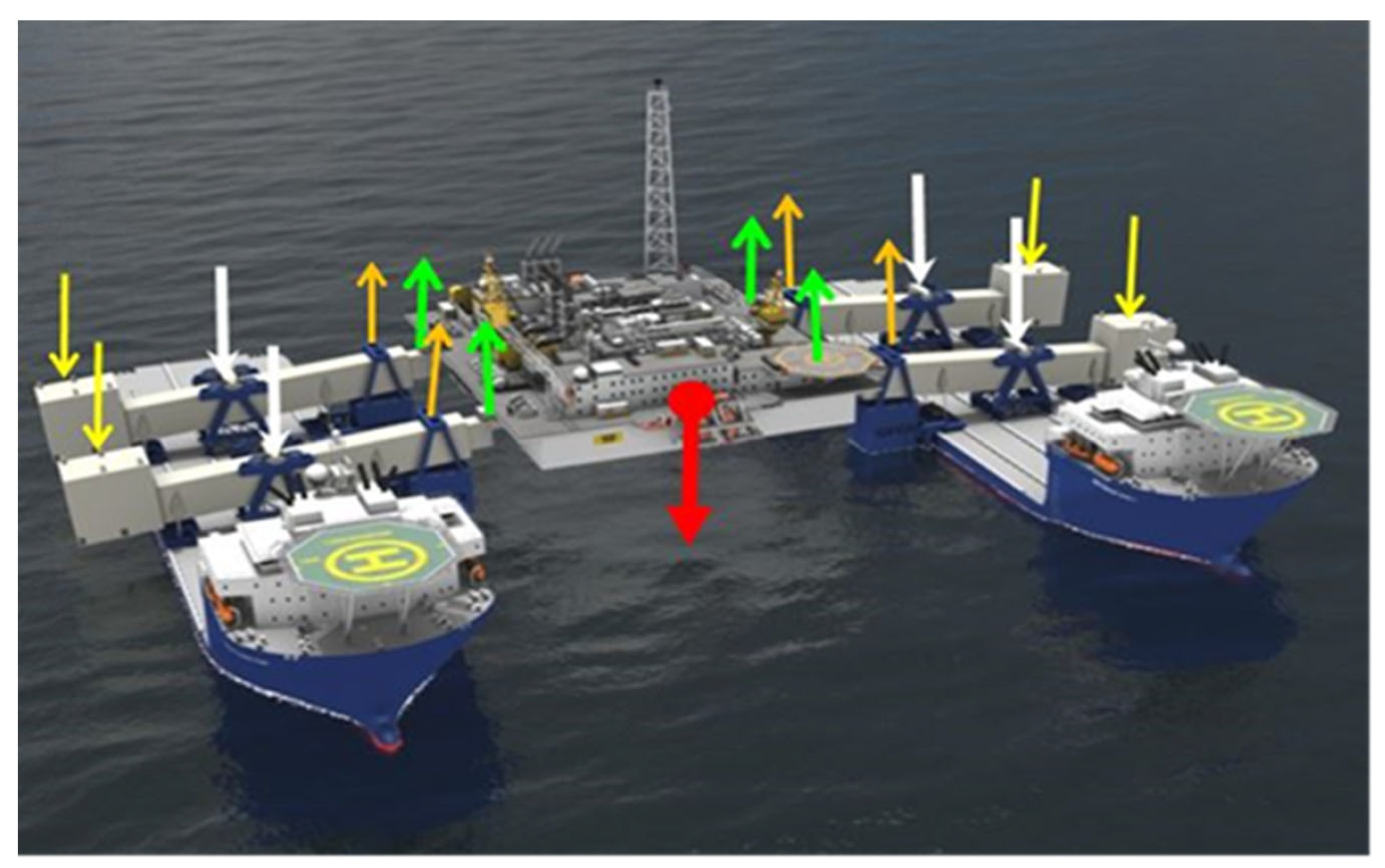
The lifting arms are connected flexibly internally. Each lifting arm can work individually, which ensures flexible installation and decommissioning of the topside, supports and submarine structures of the drilling and exploitation platforms. The lifting arms and the hulls are connected tightly with a stable internal structure. The lifting principle of the solution is illustrated in Figure 2. The buoyancy tanks of the lifting arms provide a moment upward (as marked by the orange arrows), the ballast tanks provide a moment downward (as marked by the yellow arrows) and the two semi-submersible barges serve as the supporting points (as marked by the white arrows) to generate a lifting force upward (as marked by the green arrows) at the end of the lifting arm, so as to lift the platform to be decommissioned.
There are multiple dynamic processes with different properties when the decommissioning system is working. When establishing the dynamics model of the lifting arm, only the dynamic process that plays a leading role needs to be analyzed. Since the stage where the lifting arm lifts the offshore platform and moves with the wave lasts the longest and is most easily affected by the waves, it is necessary to carry out a dynamic analysis of the lifting arm in this stage.

3. Dynamic Model of Lifting Arm

The lifting arm system mainly consists of a semi-submersible barge, main boom support, ballast tank, main boom and buoyance tank, as shown in Figure 3.
The dynamic model of the simplified main boom–telescopic arm system is shown in Figure 4.
Parameters of the dynamic model of the simplified main boom–telescopic arm system are shown in Table 1.

3.1. Establishment of Flexible Lifting Arm Dynamic Equation

The Element Characteristics Matrix of the Flexible Lifting Arm

Use the origin of the floating coordinates, the element generalized coordinates and the angle between the inertial coordinate and the floating coordinate system to form the state vector q i of the lifting arm element.
q i = r i θ i q f , i T = r i x , r i y , θ i , q f 1 , q f 2 , q f 3 , q f 4 , q f 5 , q f 6 T
The velocity vector of the flexible element can be transformed into the following expression:
r ˙ p = I r ˙ i + θ ˙ i P + A T q ˙ f , i
where I is the second-order element matrix, P = I ˜ A u 0 , i + u f , i . By integrating the flexible element over the entire flexible arm, the following element kinetic energy expression can be obtained:
E k = 1 2 V ρ r ˙ p T r ˙ p d V = 1 2 q ˙ i T M q ˙ i
where ρ is the element density and M is the element mass of the lifting arm
Then, the element mass matrix of the lifting arm can be written as follows:
M = M 11 M 12 M 13 M 22 M 23 s y m m e t r i c M 33
where the block matrices are as follows:
M 11 = V ρ I d V = m 0 0 m
M 12 = V ρ P d V = m 12 6 l + q f 1 + q f 4   s i n   θ i 6 q f 2 + l q f 3 + 6 q f 5 l q f 6   c o s   θ i 6 l + q f 1 + q f 4   c o s   θ i + 6 q f 2 + l q f 3 + 6 q f 5 l q f 6   s i n   θ i
M 13 = V ρ A T d V = m 2   c o s   θ i   s i n   θ i l   s i n   θ i 6   c o s   θ i   s i n   θ i l   s i n   θ i 6   s i n   θ i   c o s   θ i l   c o s   θ i 6   s i n   θ i   c o s   θ i l   c o s   θ i 6
M 22 = V ρ P T P d V = l 2 + l q f 1 + 2 l q f 4 m 3
M 23 = V ρ P T A T d V = m 20 2 l q f 2 + 3 l q f 3 + 9 q f 5 2 l q f 6 3 3 l + 7 q f 1 + 3 q f 4 2 l + 3 l q f 1 + 2 l q f 4 3 9 q f 2 + 2 l q f 3 + 2 q f 5 3 l q f 6 3 7 l + 9 q f 1 + 2 l q f 4 3 l + 2 l q f 1 + 3 l q f 4 3
M 33 = V ρ A T T A T d V = m 1 3 0 0 1 6 0 0 13 35 11 l 210 0 9 70 13 l 420 l 2 105 0 13 l 420 l 2 140 1 3 0 0 13 35 11 l 210 s y m m e t r i c l 2 105
The mass matrix under a floating coordinate system shall be transformed to the inertial coordinate system in order to study the flexible lifting arm consisting of multiple elements. q i e is the state vector under the inertial coordinate system, so,
q i e = r i x , r i y , θ i , Q f 1 , Q f 2 , Q f 3 , Q f 4 , Q f 5 , Q f 6 T
Then,
q f 1 = Q f 1   c o s   θ i + Q f 2   s i n   θ i   , q f 2 = Q f 1   s i n   θ i + Q f 2   c o s   θ i   , q f 3 = Q f 3 q f 4 = Q f 4   c o s   θ i + Q f 5   s i n   θ i   , q f 5 = Q f 4   s i n   θ i + Q f 5   c o s   θ i   , q f 6 = Q f 6
So, the coordinate-transformation matrix of the element state vector of the flexible lifting arm is:
q i = Z q i e   , q i T = q i e T Z T
where,
Z = I 3 × 3 Z f = 1 1 1   c o s   θ i   s i n   θ i 0   s i n   θ i   c o s   θ i 0 0 0 1   c o s   θ i   s i n   θ i 0   s i n   θ i   c o s   θ i 0 0 0 1
So, the element mass matrix of the lifting arm under the inertial coordinate system is:
M e = Z T M Z
The expression of the element deformation energy in the floating coordinate system is:
E p = 1 2 0 l E I u f 2 2 + E a u f 1 2 d x = 1 2 q f T K f q f
where u f 1 and u f 2 represent the axial displacement and lateral displacement, respectively. The above expression can be further deformed as follows:
E p = 1 2 0 l u f 1 u f 2 E a E I u f 1 u f 2 d x
where,
u f 1 = q f 4 q f 1 l = 1 l 0 0 1 l 0 0 q f 1 q f 2 q f 3 q f 4 q f 5 q f 6
u f 2 = 6 q f 2 + 6 q f 5 4 l q f 3 2 l q f 6 l 2 = 0 6 l 2 4 l 0 6 l 2 2 l q f 1 q f 2 q f 3 q f 4 q f 5 q f 6
u f 1 u f 2 = 1 l 0 0 1 l 0 0 0 6 l 2 4 l 0 6 l 2 2 l q f 1 q f 2 q f 3 q f 4 q f 5 q f 6
Then, the stiffness matrix is as follows:
K = 0 3 × 3 0 6 × 3 E a l 0 0 E a l 0 0 12 E I l 3 6 E I l 2 0 12 E I l 3 6 E I l 2 4 E I l 0 6 E I l 2 2 E I l E a l 0 0 12 E I l 3 6 E I l 2 s y m m e t r i c 4 E I l
The matrix of the coordinates is transformed so as to obtain the stiffness matrix in the inertial coordinate system.
K e = Z T K Z
The active force received by the lifting arm is converted into the generalized force of the element generalized coordinates according to the plane stress of the lifting arm, so the active force vectors of the lifting arm are as follows:
q 2 L 2 = q 2 L 2   s i n   θ , q 2 L 2   c o s   θ T     q 1 L = ( q 1 L   s i n   θ , q 1 L   c o s   θ ) T G p = ( G p   s i n   θ , G p   c o s   θ ) T             F f = F f   s i n   θ , F f   c o s   θ T                                 G y = G y   s i n   θ , G y   c o s   θ T                            
According to the principle of virtual displacement, the virtual work of the concentrated force F Δ on any point P of the flexible body is as follows:
Δ W = F Δ T Δ r p = F Δ T Δ r i + P Δ θ i + A T Δ q f , i                 = F T Δ r i T Δ θ i Δ q f , i T T
where F is the generalized force vector. It is written in a block matrix expression as follows:
F = F r T F θ F f T T
where,
F r T = F Δ T I F θ = F Δ T P F f T = F Δ T A T
Then, the generalized force of the self-weight of the main boom on the left side of the supporting point is as follows:
q 2 L 2 = q 2 L 2   s i n   θ , q 2 L 2   c o s   θ ,   1 2 q 2 L 2 2   c o s   2 θ ,   1 2 q 2 L 2   s i n   2 θ ,   1 2 q 2 L 2   c o s 2   θ , l 12 q 2 L 2   c o s   2 θ ,   1 2 q 2 L 2   s i n   2 θ ,   1 2 q 2 L 2   c o s   2 θ , 1 12 q 2 L 2 2   c o s   2 θ T
The generalized force of the self-weight of the main boom on the right side of the supporting point is as follows:
q 1 L = q 1 L   s i n   θ , q 1 L   c o s   θ , 1 2 q 1 L 2   c o s   2 θ , 1 2 q 1 L   s i n   2 θ , 1 2 q 1 L   c o s   2 θ , l 12 q 1 L   c o s   2 θ , 1 2 q 1 L   s i n   2 θ , 1 2 q 1 L   c o s   2 θ ,   1 12 q 1 L 2   c o s   2 θ T
The generalized force of the offshore platform self-weight is as follows:
G p = G p   s i n   θ , G p   c o s   θ , G p L   c o s   2 θ , 0 , 0 , 0 , G p   s i n   2 θ , G p   c o s   2 θ , 0 T
The generalized force of the buoyancy tank is as follows:
F f = F f   s i n   θ , F f   c o s   θ , L 1 F f   c o s   2 θ , 0 , 0 , 0 , F f   s i n   2 θ , F f   c o s   2 θ , 0 T
The generalized force of the ballast tank is as follows:
G y = G y   s i n   θ , G y   c o s   θ , G y L 2   c o s   2 θ , 0 , 0 , 0 , G y   s i n   2 θ , G y   c o s   2 θ , 0 T
The generalized force of the lifting arm element in the luffing plane can be obtained as follows according to the generalized forces above.
F = q 2 L 2 + q 1 L + G p + F f + G y
For a system with n degrees of freedom, the Lagrange equation can be expressed as:
d d t E k q ˙ i e E k q i e + E p q i e = F i n , j = 1 , 2 , , n
where q ˙ i = q i / t is the generalized velocity and F i n is the non-conservative generalized force with respect to generalized coordinates q i .
From the derived element kinetic and potential energies, the dynamic equation of the flexible body can be derived as follows:
M i e q i q ¨ i e + K i e q i q i e = F

3.2. Solution of Flexible Lifting Arm Dynamic Equation

It is assumed that the sectional view of the lifting arm is a figure that is symmetrical up–down and left–right. The value of E I is calculated to be 2.68 × 10 13 N·m2, E a = 3.16 × 10 12 N.
The dynamic simulation model of the flexible lifting arm is established. Furthermore, the characteristics matrix and the generalized vector are as follows:
M H = M e = m 11 m 12 m 19 m 22 m 29 s y m m e t r i c m 99
K H = K e = k 11 k 12 k 19 k 22 k 29 k 99
F H = F 1   , F 2   , F 3   , F 4   , F 5   , F 6   , F 7   , F 8   , F 9 T
Equations (35)–(37) are substituted in to Equation (34) where the following is obtained:
m 11 m 12 m 19 m 22 m 29 s y m m 99 r ¨ x r ¨ y q ¨ f 6 + k 11 k 12 k 19 k 22 k 29 s y m k 99 r x r y q f 6 = F 1 F 2 F 9
(1)
Parameters of Lifting Arm Model
L = 41.5   m ,   q 1 L = 623 , 290   kg ,   L 2 = 22   m ,   q 2 L 2 = 216 , 267.5   kg ,   L 1 = 31.5   m ,   G p = 24 , 525   kN
G y = 20 , 702   kN ,   F f = 13 , 497   kN ,   E I = 2.68 × 10 13   N m 2 ,   E a = 3.16 × 10 12   N
(2)
System’s Initial Conditions and Boundary Conditions
q t = 0 H = 41.37 , 3.25 , 0 , 0 , 0 , 0 , 0 , 0 , 0 T
q ˙ t = 0 H = 0 , 0 , 0 . 69 π 180 , 0 , 0 , 0 , 0 , 0 , 0
r x = r ˙ x = r ¨ x = 0 , r y = r ˙ y = r ¨ y = 0 , q f 1 = q ˙ f 1 = q ¨ f 1 = 0 , q f 2 = q ˙ f 2 = q ¨ f 2 = 0
According to the characteristics matrix and the generalized force vector, a simulation model is established in MATLAB for the solution.

4. Dynamic Analysis

4.1. Dynamic Numerical Analysis of the Lifting Arm

The dynamic model of the lifting arm is solved and the simulation results of the flexible lifting arm in the luffing plane are shown in Figure 5 and Figure 6, namely, the lateral displacement response at the lifting end of the flexible lifting arm during the lifting process of the offshore platform.
It is clearly shown in Figure 5 that the maximum deformation of the lifting arm is 221.63 mm within 1/4 cycle, and the initial position of the lifting arm is close to horizontal, so the lateral deformation of the top node of the flexible lifting arm at this position is the largest. The closer it is to the top node of the lifting arm vertically, the smaller the horizontal deformation. As time goes on, the angle between the flexible lifting arm and the horizontal line becomes bigger and bigger, while the component of the generalized forces in the vertical direction becomes smaller and smaller, so the deformation of the flexible lifting arm decreases gradually. Under actual working conditions, the luffing angle of the lifting arm is very small, usually about 10 degrees, so only the first 10 s is required for the lifting process, as shown in Figure 6. Figure 7 shows the luffing angular velocity of the bottom node of the lifting arm. It can be seen from the figure that the angular velocity also changes periodically, but the magnitude of the change is relatively small and can be ignored, meaning the lifting arm still maintains a uniform luffing variation.
The given parameters of the decommissioning system are not unique values, and in practice, the system needs to deal with different environments and offshore platforms. Therefore, different luffing angular velocities and lifting loads based on common sea states and offshore platforms to be decommissioned are selected for simulation and analysis, as shown in Table 2:
Next, 1/4 circumferential luffing dynamic simulations with parameters of group #2 and #3 were carried out. Comparing Figure 8 and Figure 9 with Figure 5, it can be concluded that with the same lifting load and different luffing angular velocities, the maximum lateral deformation value at the lifting end of the lifting arm is basically stable, but with different luffing angular velocities, the time it takes to reach the maximum deformation is different, and the maximum values are 220.58 mm and 223.64 mm, respectively. This shows that as long as the lifting load is the same, the maximum lateral deformation of the lifting arm at the lifting end remains basically the same.
Simulations with parameters of group #1 and #4 were carried out. Comparing Figure 10 with Figure 5, it can be concluded that with the same luffing angular velocity and different lifting loads, the lateral deformation value at the lifting end of the lifting arm decreases, but the change period of the curve is not changed. The maximum deformation value is 181.31 mm. The lifting load ratio of group #1 and #4 is 1.25, and the maximum deformation ratio is 1.22. The two ratios are very close. It can be concluded that the lateral deformation at the lifting end of the lifting arm is proportional to the lifting load.

4.2. Modal Analysis of the Lifting Arm System

The main performance parameters of the lifting arm are as shown in Table 3.
The ANSYS Workbench (ANSYS, Inc., Canonsburg, PA, USA) was used to perform free modal analysis of the lifting arm of the decommissioning system. The natural frequencies of the first eight fundamental modes were extracted, as shown in Table 4, and the main vibration mode was as shown in Figure 11.
It can be seen from Table 4 that when the frequency of the external excitation is higher than or equal to 1 Hz, the lifting arm is prone to resonating at various natural frequencies. However, the maximum frequency of the external excitation in the marine environment is 0.2 Hz, so the possibility of lifting arm resonance occurring is minimal.
From the analysis of the inherent dynamic characteristics of the lifting arm, it can be seen that orders #7 and #8 have no obvious modes of vibration; the modes of vibration corresponding to the natural frequencies of orders #1, #2 and #4 swing in the luffing plane; the modes of vibration corresponding to the natural frequency of order #3 swings in the slewing plane; and orders #5 and #6 appear as torsional pendulums. It can be considered that the dynamic characteristics of the first two orders are the fundamental frequency of the lifting arm, and they affect the lifting, amplitude and slewing of the whole decommissioning system.

4.3. Transient Dynamic Analysis

In the first stage, take the speed of the lifting arm before making contact with the offshore platform as 0.6 or 0.7 m/s. Then, the transient dynamic analysis results of the lifting arm in the first stage are as shown in Figure 12.
It can be seen from Figure 12 that when the lifting arm makes contact with the offshore platform at different speeds, the lifting arm shakes due to the presence of impact load. When the speed is 0.7 m/s, the shaking amplitude of the ballast tank is greater than the deformation of about 160 mm of the ballast tank under a static load, and large amplitude sloshing will easily cause the instability of the decommissioning system. When the speed is 0.6 m/s, the displacement response of the ballast tank end is about 130 mm, which is equivalent to the deformation of the lifting arm under a static load. Therefore, the lifting arm should make contact and lift the offshore platform at a speed of 0.6 m/s.
After the first stage, the buoyancy tank is still shaking, and then the system enters the second stage. As the water in the buoyancy tank is continuously discharged, the buoyancy of the tank increases until the offshore platform is lifted. During this process, the displacement of the lifting arm at the lifting end increases gradually. Take the wave under the fifth-grade (rough) sea state as the simulated working condition. Since one ocean wave period is 10 s, the duration of the second stage is 10 s. The integral time step is 0.01 s, the starting time is set to 0~2 s, the constant speed time is 2~8 s, the braking time is 8~10 s and the smooth lifting speed of the offshore platform is set to 0.6 m/s. The transient dynamic analysis results of the second stage are as shown in Figure 13.
It can be seen from Figure 13 that the displacement curve of the lifting end of the lifting arm shakes around 250 mm, the shaking amplitude shows a decreasing trend and the vibration time is long. Regardless of the effect of waves, as time goes on, the lifting end of the lifting arm transitions from a transient response to a steady-state response, and the steady-state response of the lifting end is almost the same as the calculated value under a static state.
In the third stage, the offshore platform is lifted as a whole. At this time, the lifting end of the lifting arm is subjected to a constant force, and the decommissioning system is in a state of balance under the action of external forces. In this process, the lifting end will not move up and down violently with the action of the waves due to the wave heave compensation used, but there is still a certain up and down movement, so an instantaneous inertial force will be generated. Similarly, take the wave under the fifth-grade (rough) sea state as the simulated working condition, and again, one ocean wave period as 10 s. The wave height is 3 m, and the amplitude of the deck movement is 0.9 m. So, in a wave cycle, the wave moves from the wave crest to the horizontal position, which means the time period of the speed changing from the minimum to the maximum value is a quarter period, namely, 2.5 s. Then, the average speed of the offshore platform’s movement up and down following the wave is 0.36 m/s, and the maximum speed is 0.565 m/s. Transient dynamic simulation of the third stage is carried out, and the analysis results are as shown in Figure 14.
Since the lifting speed of the platform is greater than the speed of the offshore platform moving up and down under the action of waves, the inertial force generated is large. So, the displacement of the lifting end in Figure 13 is larger than that in Figure 14. When the offshore platform is gradually stabilized, the displacement response of the lifting arm at the lifting end is basically the same as that of the second stage.
Under the action of a wave heave compensation mechanism of the lifting arm system, the process of lifting the offshore platform smoothly by the lifting arm is assumed to be a static problem. The action points of each force are known, and the value of each force is obtained by using the moment balance. The static displacement nephogram shown in Figure 15 and static stress nephogram shown in Figure 16 of the lifting arm are obtained through simulation analysis.
The displacement response at the lifting end of the lifting arm in a static state is compared with those of the two transient lifting operations.
It can be seen from Figure 15 that the maximum displacement response of the lifting end when the lifting arm lifts the offshore platform is 360 mm. From the displacement response trend at the lifting end, it can be concluded that the displacement will eventually settle at about 250 mm, which is almost the same as the 247.7 mm under a static load. The ratio of the transient maximum displacement to the steady-state displacement is as follows: i = 360 247.7 = 1.45 .
It can be seen from Figure 16 that the maximum displacement response of the lifting end when the decommissioning system is under the action of waves is 330 mm. From the displacement response trend of the lifting end, it can be concluded that the displacement will also eventually settle at about 250 mm, which is almost the same as the 247.7 mm under a static load. The ratio of the transient maximum displacement to the steady-state displacement is as follows: i = 330 247.7 = 1.33 .

5. Dynamic Experiment Analysis and Verification of the Lifting Arm System

5.1. Hydrodynamic Experiment Method with an Integrated Decommissioning Multi-Dimensional Vibration Test Bench

In this paper, a hydrodynamic experiment method with an integrated decommissioning multi-dimensional vibration test bench is firstly proposed. The land-based vibration platform experiment replaces the pool experiment, namely, the six-degrees-of-freedom vibration platform is used to simulate the motion of the semi-submersible barge deck under actual sea states. A servo electric cylinder is used to provide a lifting moment to simulate the acts of the buoyancy tank and the ballast tank. Compared with the pool experiment, the multi-dimensional vibration test bench experimental method greatly saves manpower and material resources, and it can also improve the experimental process by strictly controlling the parameters of the experiment, so as to obtain accurate results and achieve the goal of artificially highlighting the main contradictions [21].
In order to design a scaled-down model of the integrated decommissioning equipment and build a multi-dimensional vibration test bench for the hydrodynamic experiments, it is necessary to derive a similitude criterion that conforms to the decommissioning equipment, to ensure consistency between the model experiment and the actual decommissioning process. It can be understood from the theory of similitude that the results obtained by model experiments can be directly extended to practical engineering [22,23]. Furthermore, the derived similitude criterion has general guiding significance for the hydrodynamic experiment method with a multi-dimensional vibration test bench.
According to the theory of similitude, the criteria of similitude are derived below:
π 1 = δ L , π 2 = θ , π 3 = A L 2 , π 4 = L 2 σ F , π 5 = ε , π 6 = L 2 E F , π 7 = μ , π 8 = L 4 ρ F T 2 , π 9 = L 2 p F , π 10 = L m F T 2 , π 11 = L k F , π 12 = L c T F , π 13 = T f , π 14 = T v L , π 15 = T 2 a L , π 16 = T 2 g L
The similitude relationship can be expressed by Equation (40).
F l δ L , θ , A L 2 , L 2 σ F , ε , L 2 E F , μ , L 4 ρ F T 2 , L 2 p F , L m F T 2 , L k F , L c T F , T f , T v L , T 2 a L , T 2 g L
According to the same π value principle of the theory of similitude, p represents the prototype variable and m represents the experimental variable.
Then,
C L = L p L m , C E = E p E m
Then, the similitude criterion of the hydrodynamic experiment with the integrated decommissioning multi-dimensional vibration test bench is obtained as shown in Table 5.

5.2. Setup of the Integrated Decommissioning Multi-Dimensional Vibration Test Bench

The geometric similitude ratio of the integrated decommissioning multi-dimensional vibration test bench is determined to be C L = 50 with the limit of the testing area and testing equipment. Motion parameters of the Six-degrees-of-freedom motion platform is shown in Table 6.
Figure 17 shows the experimental platform of the double-ship integrated offshore platform decommissioning equipment, in which a fold-back-type (the screw spindle is parallel to the motor spindle) servo electric cylinder is used. The model of the servo electric cylinder is 4120-65-190 (Suzhou Fengdarui Automation Equipment Technology Co., Ltd., Suzhou, China), and the model of the servo driver is ASD-B2-0221-B of Delta (Delta Electronics, Inc., Guangzhou, China); the industrial computer is equipped with an Intel I3 CPU, 4 G memory and 128 G solid-state hard disk with 15-inch industrial touch screen and 485 bus expansion (Suzhou Fengdarui Automation Equipment Technology Co., Ltd., Suzhou, China). The attitude sensor model is WT901C485 (Suzhou Fengdarui Automation Equipment Technology Co., Ltd., Suzhou, China) and the switch model is TL-SF1008(TP-LINK, Inc., Shenzhen, China).
In addition, according to the principle of material stress–strain similitude, there are two positions where the maximum strain occurs based on the finite element analysis of the lifting arm mentioned above. Therefore, the strain gauges are installed: first, around the main boom support, which is referred to as A Section; and second beneath the contact point between the lifting end main boom and the telescopic arm, which is referred to as B Section. According to the design requirements of the model, the DH5902N dynamic test and analysis system is selected. The system consists of: (1) laser displacement sensor(Suzhou Fengdarui Automation Equipment Technology Co., Ltd., Suzhou, China); (2) DH5902N 32-channel data acquisition processor(Beijing Xinhang Technology Co. Ltd., Beijing, China) to collect the strain data of the strain gauge in real-time, as shown in Figure 18; (3) data collector connected to a computer through a network cable via which it sends data to the computer to record in real-time, and post-processing with DHDAS test software (Donghua Testing Technology Co., Ltd., Jingjiang, China).

5.3. Analysis of the Testing Results

This experiment simulates the decommissioning operation conditions under third-grade (slight), fourth-grade (moderate) and fifth-grade (rough) sea states. Fuzzy PID control is adopted. The integrated decommissioning of the offshore platform under each sea state is conducted, where the motion parameters of the deck are as shown in Table 7.
We simulate the strain and displacement response at the lifting end of a single lifting arm when the deck heaves under the third-grade (slight), fourth-grade (moderate) and fifth-grade (rough) sea states.
(1)
When the deck is heaving, the curve of the strain on the lifting arm under the fifth-grade (rough) sea state is as shown in Figure 19a,b.
The tensile strength of organic glass is 75.8 MPa and the compressive strength is 135.9 MPa. The supporting point of the lifting arm is in a stretched state, and the contact area between the main boom and the telescopic arm at the lifting end is in a squeezed state. So, the allowable stress values are different for the two positions. Taking a safety factor of 1.5, the allowable stress values are 50.53 MPa and 90.6 MPa, respectively. The stress values of the two regions are calculated according to the strain values of sections A and B in Figure 19. The tensile stress is 5.63 MPa and the compressive stress is 9.98 MPa, both of which are less than the allowable stress of the experimental model material. Then the stress generated in the third-grade (slight) and fourth-grade (moderate) sea states is also less than the allowable stress of the model material.
(2)
When the deck is heaving, a laser displacement measuring instrument is used to measure the curve of the displacement in the vertical direction at the lifting end under various sea sates, and the curve with a relatively stable change is selected, as shown in Figure 20a–c.
It can be seen from Figure 20a–c that during the entire heave motion cycle, there is only a relatively large displacement change at the highest point and the lowest point due to the sudden change of velocity. By comparing Figure 20a with the input parameters of the third-grade (slight) sea state, it can be concluded that the deformation at the lifting end of the lifting arm experimental model is about 2.2 mm. Similarly, it can be determined that the deformations of the lifting arm experimental model under the fourth-grade (moderate) and fifth-grade (rough) sea states are about 3 mm and 4.15 mm, respectively. As the sea states get more severe, the deformation of the experimental model of the lifting arm worsens.
According to Figure 19a,b, it can be seen that the stress values of the two areas are calculated from the strain values of the two areas of the experimental model. The tensile stress is 5.63 MPa and the compressive stress is 9.98 MPa. The maximum value is similar to the static stress value of 10.46 MPa under the principle of similitude. In addition, according to Figure 20c, the displacement response value in the vertical direction at the lifting end of the fifth-grade (rough) sea state is 4.15 mm, and the deviation between the experimental value and the simulation value of 4.954 mm is about 15%, which is within the allowable range.

6. Conclusions

Based on the analysis of the proposed method, some conclusions are given as follows:
(1)
To support the decommissioning of large-scale offshore facilities, double-ship integrated offshore platform decommissioning equipment was designed, the working process of the decommissioning system was specified and dynamic calculation conditions of the lifting arm were established. A dynamic model of the lifting arm system was established, and a dynamic equation of the flexible lifting arm system was obtained. Based on the numerical simulation model, a multi-input and multi-output module was created using the S function, the dynamic equation of the flexible lifting arm was solved and the numerical solution to the decommissioning system’s dynamic response was obtained.
(2)
Modal analysis was carried out for the key stressed components of the lifting arm system, and the vibration response of the lifting arm in the luffing plane was obtained. Transient analysis of the lifting arm under certain working conditions (including lifting and luffing) was carried out on the basis of modal analysis. It can be seen from a comparison with the static calculation results that when the transient analysis results tended to be stable, the transient response was basically consistent with the static calculation results.
(3)
A hydrodynamic experiment method with the integrated decommissioning multi-dimensional vibration test bench was proposed, and the similitude criteria for the decommissioning equipment were deduced. The derived similitude criteria have general guiding significance for the hydrodynamic experiment method with the multi-dimensional vibration test bench. A hydrodynamic simulation test bench was built, and the displacement response at the lifting end of the lifting arm under various sea states, and the strain value of the point bearing the maximum stress under the fifth-grade (rough) sea state, were obtained through experiments. The results of the three different dynamic characteristic analysis methods were compared and analyzed. The results of the simulation analysis, numerical analysis and experimental analysis after transformation based on the principle of similitude were compared and the deviation between the three was about 10~15%. This was within the allowable range, which further proved the accuracy of the three analysis methods.
As a new type of marine equipment, the double-ship integrated offshore platform decommissioning equipment is currently in the research and development stage, with very little research on it at home and abroad. In this research, the dynamic characteristics of a designed integrated decommissioning system were studied, and according to the principle of similitude, a hydrodynamic experiment method is proposed in this paper with an integrated decommissioning multi-dimensional vibration test bench. The model test bench of the decommissioning system was designed and built, and a dynamic response experiment was carried out. The results of the numerical analysis, simulation analysis and experimental analysis based on the hydrodynamic experimental method with the multi-dimensional vibration test bench showed that the three analysis methods verified each other, and the results were effective and accurate. The research has laid a theoretical foundation for the study of this kind of equipment and has reference value for follow-up research in the future.

Author Contributions

Conceptualization, W.X. and C.L.; methodology, W.X. and C.L.; software, C.L. and L.F.; validation, C.L., L.F. and W.X.; formal analysis, C.L., L.F. and W.X.; investigation, Q.L.; resources, Q.L.; data curation, L.T.; writing—original draft preparation, W.X. and C.L.; writing—review and editing, C.L.; supervision, W.X.; project administration, W.X. and C.L. All authors have read and agreed to the published version of the manuscript.

Funding

This research was funded by the [Ministry of Industry and Information Technology of China] grant no. [MC-201713-H02], funder ID: [10.13039/501100006579] through the project “Research on Key Technologies of Integrated Dismantling Equipment for Super Large Offshore Oilfield Facilities”.

Data Availability Statement

The research data is unavailable due to privacy.

Acknowledgments

This work was financially supported by the Ministry of Industry and Information Technology of China (grant no. MC-201713-H02; funder ID: 10.13039/501100006579) through the project “Research on Key Technologies of Integrated Dismantling Equipment for Super Large Offshore Oilfield Facilities”.

Conflicts of Interest

The authors declare no conflict of interest.

References

  1. Wu, F.; Yu, C.J.; Jia, X.; Ci, H.S.; Sun, J.L. Offshore Oil and Gas Platform Decommissioning Research. Oceans 2014, 2, 963–966. [Google Scholar]
  2. Vidal, P.D.J.; Gonzalez, M.O.A.; de Vasconcelos, R.M.; de Melo, D.C.; Ferreira, P.D.; Sampaio, P.G.V.; Silva, D.R.D. Decommissioning of offshore oil and gas platforms: A systematic literature review of factors involved in the process. Ocean Eng. 2022, 255, 111428. [Google Scholar] [CrossRef]
  3. Tian, Q.H.; Wang, T.; Wang, Y.X.; Wang, Z.W.; Liu, C.W. A two-level optimization algorithm for path planning of bionic robotic fish in the three-dimensional environment with ocean currents and moving obstacles. Ocean Eng. 2022, 266, 112829. [Google Scholar] [CrossRef]
  4. Liu, P.; Liu, Y.H.; Wei, X.X.; Xin, C.; Sun, Q.; Wu, X.L. Performance Analysis and Optimal Design Based on Dynamic Characteristics for Pressure Compensated Subsea All-Electric Valve Actuator. Ocean Eng. 2019, 191, 106568. [Google Scholar] [CrossRef]
  5. Lan, P.; Lu, N.L.; Ding, Q.Y.; Sun, L.N. Explicit Expression for Precise Kineto-elastodynamic Analysis. J. Nanjing Univ. Sci. Technol. 2005, 2, 153–157. [Google Scholar]
  6. Guo, A.; Zhou, Z.; Zhu, X.P.; Zhao, X. Coupled Flexible and Flight Dynamics Modeling and Simulation of a Full-Wing Solar-Powered Unmanned Aerial Vehicle. J. Intell. Robot. Syst. 2021, 101, 56. [Google Scholar] [CrossRef]
  7. Chung, Y.C.; Wu, Y.R. Dynamic modeling of a gear transmission system containing damping particles using coupled multi-body dynamics and discrete element method. Nonlinear Dynam. 2019, 98, 68–73. [Google Scholar] [CrossRef]
  8. Gasbarri, P.; Sabatini, M.; Pisculli, A. Dynamic modelling and stability parametric analysis of a flexible spacecraft with fuel slosh. Acta. Astronaut. 2016, 127, 141–159. [Google Scholar] [CrossRef]
  9. Sun, D.X.; Liu, X.H. Flexible Dynamic Analysis of Hydraulic Excavator’s Boom. Adv. Mater. Res. 2011, 328, 2220–2223. [Google Scholar] [CrossRef]
  10. Zhang, D.Y.; Luo, J.J.; Yuan, J.P. Dynamics modeling and attitude control of spacecraft flexible solar array considering the structure of the hinge rolling. Acta Astronaut. 2019, 153, 60–70. [Google Scholar] [CrossRef]
  11. Sheng, W.J.; Mao, L.; Wang, Z.H. Dynamic Analysis of an Airborne Radar Frame Structure. Mech. Eng. Autom. 2020, 86–88. [Google Scholar]
  12. Do, T.T.; Vu, V.H.; Liu, Z.H. Linearization of dynamic equations for vibration and modal analysis of flexible joint manipulators. Mech. Mach. Theory. 2022, 167, 104516. [Google Scholar] [CrossRef]
  13. Wang, F.Q.; Rui, Z.Y.; Zhao, D.P.; Lei, C.L. Structural Dynamic Analysis and Optimization of High-Speed Precision Machining Center Column. Adv. Mater. Res. 2013, 655–657, 48–51. [Google Scholar] [CrossRef]
  14. Wu, J.J. The complete-similitude scale models for predicting the vibration characteristics of the elastically restrained flat plates subjected to dynamic loads. J. Sound. Vib. 2003, 268, 1041–1053. [Google Scholar] [CrossRef]
  15. Ramu, M.; Raja, V.P.; Thyla, R.P. Establishment of structural similitude for elastic models and validation of scaling laws. KSCE J. Civ. Eng. 2013, 17, 139–144. [Google Scholar] [CrossRef]
  16. Wu, J.J. Prediction of the dynamic characteristics of an elastically supported full-size flat plate from those of its complete-similitude scale model. Comput. Struct. 2006, 84, 102–114. [Google Scholar] [CrossRef]
  17. Rezaeepazhand, J. Structural Similitude for Buckling of Delaminated Beams. In Proceedings of the International Conference on fracture and Damage Mechanics FDM 2008, Department of Mechanical Engineering Ferdowsi University of Mashhad P.O. Box 91775-1111, Mashhad, Iran, 9–11 September 2008; pp. 609–612. [Google Scholar]
  18. Kim, N.S.; Lee, J.H.; Chang, S.P. Equivalent multi-phase similitude law for pseudodynamic test on small scale reinforced concrete models. Eng. Struct. 2008, 31, 834–846. [Google Scholar] [CrossRef]
  19. Singhatanadgid, P.; Songkhla, A.N. An experimental investigation into the use of scaling laws for predicting vibration responses of rectangular thin plates. J. Sound. Vib. 2007, 311, 314–327. [Google Scholar] [CrossRef]
  20. Zhu, Y.P.; Wang, Y.; Luo, Z.; Han, Q.K.; Wang, D.Y. Similitude design for the vibration problems of plates and shells: A review. Front. Mech. Eng. 2017, 12, 253–264. [Google Scholar] [CrossRef]
  21. Xu, Z.D.; Miao, A.N. Experimental and theoretical study on a novel multi-dimensional vibration isolation and mitigation device for large-scale pipeline structure. Mech. Syst. Signal Process. 2019, 129, 546–567. [Google Scholar] [CrossRef]
  22. Raze, G.; Kerschen, G. Multimodal vibration damping of nonlinear structures using multiple nonlinear absorbers. Int. J. Nonlin. Mech. 2019, 1129, 103308. [Google Scholar] [CrossRef]
  23. Guo, X.Q.; Li, X.; He, Y.F.; Liu, J.; Wang, G.R.; Mao, L.J.; Wang, J.X. Investigation on three-dimensional vibration model and response characteristics of deep-water riser-test pipe system. Commun. Nonlinear. Sci. 2022, 109, 106296. [Google Scholar] [CrossRef]
Figure 1. Double-ship Integrated Offshore Platform Decommissioning Solution.
Processes 11 00645 g001
Figure 2. Illustration of the Lifting Principle.
Processes 11 00645 g002
Figure 3. Lifting Arm System Structure.
Processes 11 00645 g003
Figure 4. Force Diagram of the Lifting Arm in the Vertical (a) and Horizontal Directions (b) with the Assumption of Self-weight Distributed Uniformly.
Processes 11 00645 g004
Figure 5. Lateral 1/4 Circumferential Deformation of the Top Node.
Processes 11 00645 g005
Figure 6. Lateral Deformation of the Top Node.
Processes 11 00645 g006
Figure 7. Luffing Angular Velocity of Bottom Node.
Processes 11 00645 g007
Figure 8. Lateral 1/4 Circumferential Deformation of the Top Node (Group #2).
Processes 11 00645 g008
Figure 9. Lateral 1/4 Circumferential Deformation of the Top Node (Group #3).
Processes 11 00645 g009
Figure 10. Lateral 1/4 Circumferential Deformation of the Top Node (Group #4).
Processes 11 00645 g010
Figure 11. Modes of Vibration of the Lifting Arm at Different Frequency Orders: (a) 1# Order Mode of Vibration (b) 2# Order Mode of Vibration (c) 3# Order Mode of Vibration (d) 4# Order Mode of Vibration (e) 5# Order Mode of Vibration (f) 6# Order Mode of Vibration (g) 7# Order Mode of Vibration (h) 8# Order Mode of Vibration.
Processes 11 00645 g011aProcesses 11 00645 g011b
Figure 12. Displacement Response of the Lifting Arm at the Ballast Tank End with the Speed of 0.6 or 0.7 m/s.
Processes 11 00645 g012
Figure 13. Displacement Response of the Lifting Arm at the Lifting End in the Second Stage.
Processes 11 00645 g013
Figure 14. Displacement Response of the Lifting Arm at the Lifting End in the Third Stage.
Processes 11 00645 g014
Figure 15. Static Displacement Nephogram of the Lifting Arm.
Processes 11 00645 g015
Figure 16. Static Stress Nephogram of the Lifting Arm.
Processes 11 00645 g016
Figure 17. (a) Integrated Decommissioning Multi-dimensional Vibration Hydrodynamic Test Bench and (b) Electric Control.
Processes 11 00645 g017
Figure 18. (a) Experiment Testing System and (b) Sensors.
Processes 11 00645 g018
Figure 19. Strain Curve of the Lifting Arm Under 5th-Grade (Rough) Sea State: (a) at A Section and (b) at B Section.
Processes 11 00645 g019
Figure 20. Curve of the Displacement in the Vertical Direction at the Lifting End: (a) under 3rd-grade sea states, (b) under 4th-grade sea states and (c) under 5th-grade sea states.
Processes 11 00645 g020
Table 1. Parameters of the Dynamic Model.
ParameterDescriptionUnit
q 1 The Uniformly-distributed Load of the Self-weight of the Main Boom Section and the Telescopic Arm Section on the Right Side of the Main Boom Support kg/m
q 2 The Uniformly-distributed Load of the Self-weight of the Main Boom Section on the Left Side of the Main Boom Supportkg/m
q 3 The Uniformly Distributed Load of the Main Boom Wind Loadkg/m
l 1 The Distance between the Action Point of the Buoyancy from the Buoyance Tank and the Main Boom Supporting Pointm
l 2 The Length of the Main Boom Section on the Left side of the Main Boom Supportm
l The Distance between the Action Point of the Offshore Platform Gravity and the Main Boom Supporting Pointm
θ The Angle at Which the Lifting Arm Deviates from the Horizontal Line °
F f The Force that the Buoyance Tank Applies to the Main BoomN
G p The Self-weight of the Offshore PlatformN
G y The Self-weight of the Ballast Tank Fully LoadedN
A x Sectional Area of the Main Boom m 2
Table 2. Setting of the Simulation Parameters.
Simulation Group Luffing   Angular   Velocity   θ (°/s) Lifting Load
G p   ( t )
10.692500
21.52500
33.52500
40.692000
Table 3. Main Performance Parameters of the Lifting Arm.
ItemParameter
Lifting Weight (t)2500
Working Amplitude (m)2.5
Lifting Height (m)6
Average Lifting Speed (m/s)0.6
Length of Lifting Arm (m)78.5
Self-weight of Lifting Arm (t)1120.7
Total Load of Ballast Tank (kN)20,702
Buoyancy of Buoyancy Tank (kN)13,497
Table 4. Natural Frequencies of the Lifting Arm.
Frequency Order Natural Frequency/HzCycle/s
10.96181.0397
22.17320.4602
32.59440.3854
44.17890.242
55.51390.2393
67.61040.1314
79.29720.1076
89.33320.1072
Table 5. Similitude Criteria of the Hydrodynamic Experiment with the Integrated Decommissioning Multi-dimensional Vibration Test Bench.
TypePhysical QuantityDimensionSimilitude Criterion
Material CharacteristicsStress σ F L 2 C σ = C E
Strain ε 1 C ε = 1
Elasticity Modulus E F L 2 C E
Material CharacteristicsPoisson’s Ratio μ 1 C μ = 1
Mass Density ρ F L 4 T 2 C ρ = C E C L
Geometric CharacteristicsLength L L C L
Linear Displacement δ L C L
Angular Displacement θ 1 C θ = 1
Sectional Area A L 2 C A = C L 2
LoadConcentrated Load F F C F = C E C L 2
Surface Load p F L 2 C p = C E
Moment M F L C M = C E C L 3
Dynamic CharacteristicsMass m F L 1 T 2 C m = C E C L 3
Rigidity k F L 1 C k = C E C L
Damping c F L 1 T C c = C E C L 3 2
Time T T C T = C L 1 2
Frequency f T 1 C f = C L 1 2
Velocity v L T 1 C v = C L 1 2
Acceleration a L T 2 C a = 1
Acceleration of Gravity g L T 2 C g = 1
Table 6. Motion Parameters of the Six-degrees-of-freedom Motion Platform.
FreedomAmplitudeVelocityAcceleration
Surging ± 100   mm ± 400   mm / s ± 0.8   g
Swaying ± 100   mm ± 400   mm / s ± 0.8   g
Heaving ± 100   mm ± 400   mm / s ± 0.8   g
Pitch ± 10 ° ± 20 ° / s ± 120 ° / s 2
Yaw ± 10 ° ± 20 ° / s ± 120 ° / s 2
Roll ± 10 ° ± 10 ° ± 120 ° / s 2
Table 7. Parameters When Simulating the Motion of the Deck under Each Sea State.
Sea StateAmplitude (mm)Pitch Cycle (s)Swaying Cycle (s)Pitch Angle (°)
3rd-Grade (Slight)13.5841.3
4th-Grade (Moderate)181062
5th-Grade (Rough)2311.5102.9
Disclaimer/Publisher’s Note: The statements, opinions and data contained in all publications are solely those of the individual author(s) and contributor(s) and not of MDPI and/or the editor(s). MDPI and/or the editor(s) disclaim responsibility for any injury to people or property resulting from any ideas, methods, instructions or products referred to in the content.

