1. Introduction
Recently, there has been a major increase in the use of printed electronics due to its several advantages such as low-cost, reduced processing steps, and less electronics waste [
1,
2,
3,
4,
5,
6]. Such advantages arise from the fact that this technique is based on additive manufacturing where layers of patterns based on solution materials are printed on top of each other to produce the desired electronic device [
7,
8]. Currently, many examples of these devices exist [
1].
Several of such electronic devices are based on polymeric substrates and include microheaters, which are considered as an integral part of different sensor applications [
9]. Microheaters are self-heating devices that comprise of a resistive metallic composition which allows them to work based on the principle of Joules’ heating [
9].
The modeling and design of electronics in general, and microheaters in specific, is conventionally of a subtractive nature in which a master template includes patterned materials that are removed selectively [
10]. This conventional manufacturing technique includes clean room fabrication and silicon (Si) micromachining technologies [
1,
2,
4].
Unlike inflexible silicon wafers, microheaters printed on polymeric foils offer the advantage of being mechanically flexible, cost-effective, having lower thermal conductivities, and are of lightweight [
1,
2,
3,
8,
11]. One of the most commonly used inks to print microheaters on plastic substrates contains silver (Ag) nanoparticles due to its low cost, compared to graphene and gold [
1,
5]. Other advantages of Ag ink include chemical stability, high electrical conductivity, high thermal conductivity, and resistance to oxidation [
5,
6,
12,
13,
14,
15]. Additionally, Ag has a low melting point that permits the creation of conductive thin films in low temperatures, which is essential to deposit the ink on flexible substrates such as polymers [
5,
6].
This work aims to reduce the power consumption of the printed microheater by reducing its effective area. We employ inkjet printing, which can print patterns as thin as 50
, on a polyimide (PI) substrate of thickness of 50
. These properties allow manufacturing of microheaters with low power consumption. Experimentally, the lowest width of a line that we could print was 110
due to Ag ink’s spreading behavior [
16]. This width size was implemented in the track width of the double meander micro heater design.
The electrical and thermal properties of the microheater were studied using finite element modelling (FEM) in COMSOL Multiphysics platform based on Joule’s heating.
In general, the process of inkjet printing on polymer substrates includes substrate preparation, treatment of substrates using plasma, drying the substrates in the oven, printing of the colloid solution, and sintering the printed substrate [
3,
12,
14]. Sintering is generally required to improve mechanical adhesion and electrical conductivity [
17]. It is especially needed in nanoparticle inks to achieve a highly conductive film by creating connections between neighboring particles [
17].
The future will include wider use of printed electronics as it has many applications such as solar cells, radio frequency identification tags (RFID), DNA microarray, stem cell printing, light emitting diodes (LED) and wearable sensors [
6,
8,
18].
Tran et al. also used nano-particle silver ink, however they used silicon/silicon dioxide substrate, which compared to our polyimide substrate, is inflexible. Additionally, microheaters printed on polymeric foils offer the advantage of being mechanically flexible, cost-effective, having lower thermal conductivities, and are of lightweight [
1,
2,
3,
8,
11].
Zhang et al. used an office-use inkjet printer which is unable to give the higher resolution used in more accurate inkjet printers. They have fabricated a silver microheater with an effective area of 1 × 1 cm. Our proposed microheater has an effective area of 720 × 720 . Which is much smaller and can result in lower power consumption.
Offenzeller et al. used screen printing whereas we used inkjet printing. Their method includes more waste as it uses a mask to deposit the ink and get the required pattern. Screen printing also includes more steps than inkjet printing which implies a more complex fabrication procedure. They also use a single meander shape compared to our double meander shape of which is the most suitable to achieve homogeneous heating over the effective area and it consumes less power than the other geometries [
9,
19,
20].
Tiwari et al. also used screen printing and a single meander geometry both of which are compared to our used technique and geometry above.
Puhringer et al. used conventional clean room fabrication technique which is a form of subtractive manufacturing. Compared to the additive manufacturing inkjet printing technique, conventional clean room techniques include more complex processes, have higher costs, and more waste. They also use a rigid silicon substrate compared to our PI flexible substrate. Additionally, a single meander geometry is used by Puhringer et al. and we use a more favorable double meander shape. The effective area that they used is much greater than ours which imply a higher power consumption value.
2. Microheater Design and Structure
Microheaters achieve high thermal efficiency through their thermally isolated structure [
21]. It is desired to achieve low power consumption while using microheaters and this is determined by the size of the material, its thermal properties, and its operating temperature [
19].
Various geometrical shapes of microheaters exist, such as S-shape, fan shape, honeycomb, spiral and double meander, for the purpose of achieving a uniform thermal distribution while considering the required application [
9,
19,
21].
Studies have shown that double meander geometry is the most suitable to achieve homogeneous heating over the effective area and it consumes less power than the other geometries [
9,
19,
21]. Also, it has been shown that decreasing the track size of the microheater ensures better temperature homogeneity [
19]. Both power consumption and robust operation are the most significant features to be considered when designing microheaters [
9].
Particularly, when using polymeric substrates, it is important to choose one that can handle high temperatures [
2]. Therefore, in this work, we realize the above by using inkjet printing technique to print an Ag microheater on 50
polyimide (PI) substrate with a relatively small effective area and small track size while considering the limitations of the inkjet printer, Ag ink, and PI substrate.
2.1. Microheater Simulations
The thermal design of the double meander microheater is optimized using COMSOL Multiphysics 5.3 which is based on Finite Element Modelling (FEM). The simulations were performed in 2-dimensions (2D) as we assume that the temperature and potential gradients perpendicular to the microheater (z-direction) are small in comparison to the gradients in the x-y plane [
10]. This is a logical assumption as the thickness of the microheater is much smaller than its length and width. The selected physics is Joule’s heating to find the maximum temperature at ideal power consumption.
The microheater double meander geometry was examined by applying different voltages to heater contacts. An operation temperature of 250 °C is reached by modifying the coefficient of convection h(hconv). Also, the resistance of the microheater is set to be 100 Ω. The simulations were conducted with a combination of different effective areas (2520 × 2520, 2320 × 2320, 2120 × 2120, 1920 × 1920, 1720 × 1720, 1520 × 1520, 1320 × 1320, 1120 × 1120, 920 × 920, 720 × 720
), track widths (70, 90, 110, 130, 150
), and gap widths (80, 105, 130, 155, 180
). The combinations that yielded lowest power consumption values are selected and summarized in
Table 1.
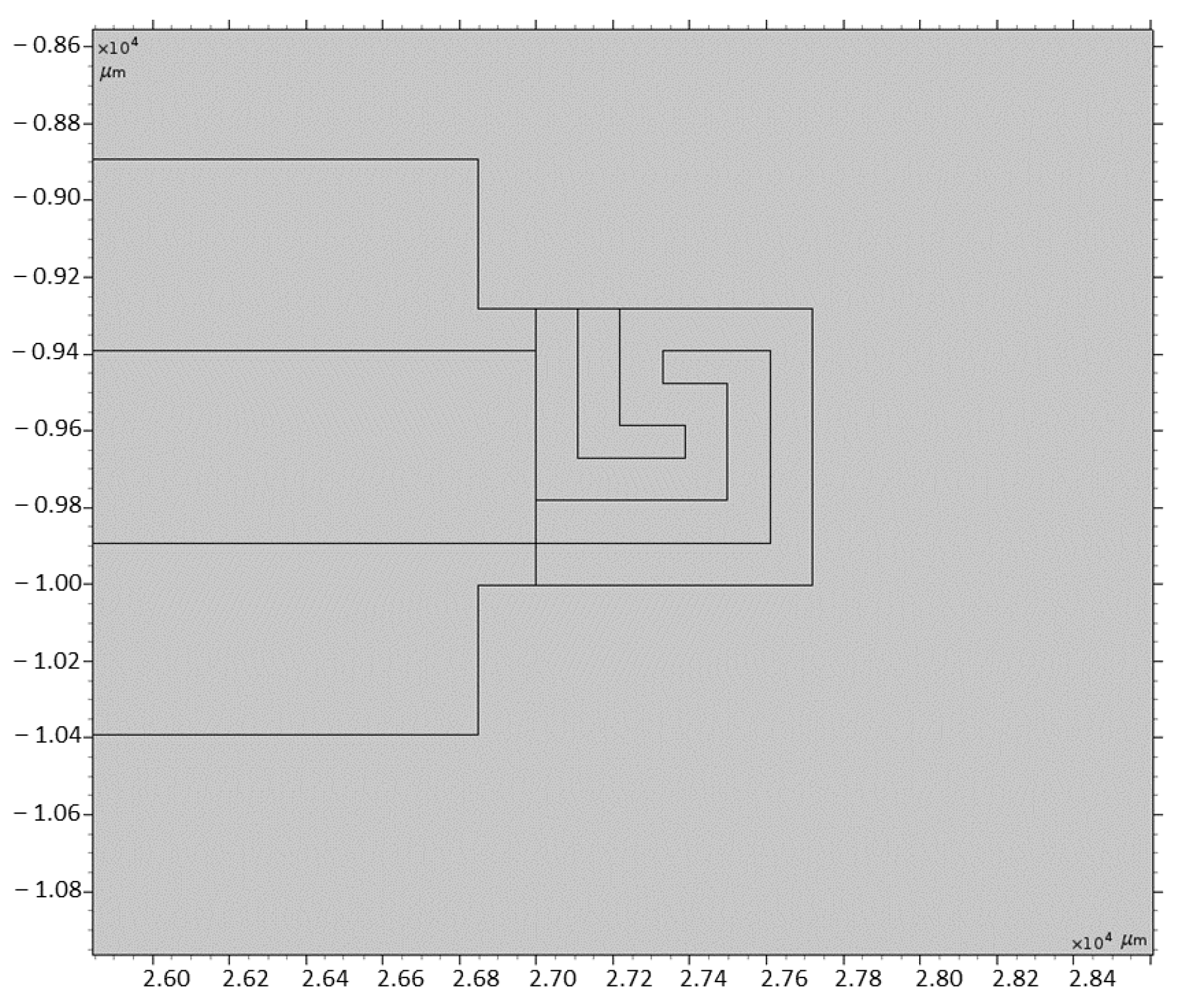
To reduce the power consumption, a small effective area of 720 × 720 μm
2
is selected and simulated. As
Table 1 shows that this value gives lowest power consumption. Due to the inkjet limitations, a track with of 110
and gap width of 110
were selected. The simulated double meander geometry for the selected parameters is shown in
Figure 1.
COMSOL database along with the supplier’s data sheets were used to determine the properties of Ag ink and PI substrate. These properties include heat capacity, electrical conductivity, density, and thermal conductivity.
Table 2 summarizes the properties of the used materials.
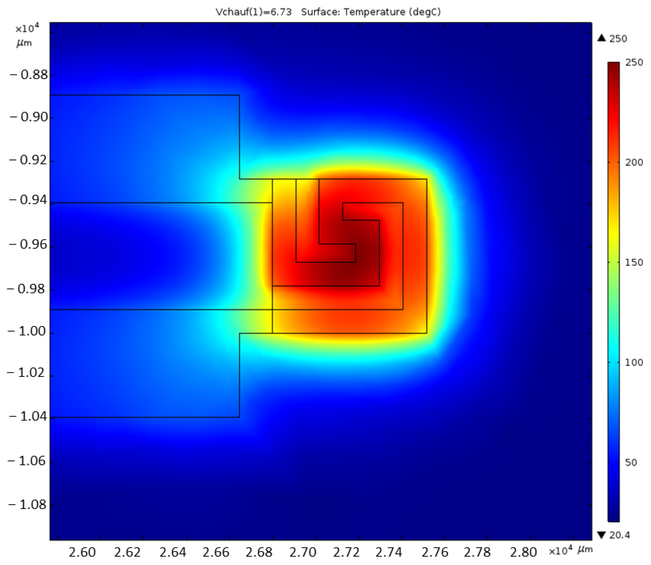
The simulation results presenting the temperature distribution over the heater structure are illustrated below.
Figure 2 represents the temperature distribution of the simulated microheater of effective area 720 × 720
with desired temperature of 250 °C.
The simulation results of Ag microheater the selected effective area and its corresponding power consumption is summarized in
Table 3. It shows that the microheater is in fact operating at 250 °C as designed.
2.2. Optimization of Settings
Inkjet printing is the most commonly used technology to fabricate chemiresistive printed flexible gas sensors using organic and inorganic inks [
7]. The inks used in printing are solutes that are dissolved in a solvent to from the required solution for inkjet printing [
7]. The thickness of the deposited layer ranges from 0.01 and 0.5
and is influenced by the evaporation of the solvent in addition to the ink viscosity [
6].
An important property is the distance between the ejected drops which is controlled when using inkjet printers to form overlapped discrete spots of the deposited ink [
9]. Also, the resolution of the printed pattern is dependent on the droplet’s size, drop overlapping, and area coverage as it is ejected from the nozzle in addition to the substrate’s wetting behavior [
10,
22]. To achieve a reliable and consistent jetting, the inks must have suitable properties [
23]. These properties include viscosity, surface tension, and particle size [
3,
6,
23]. They greatly affect on drop velocity, drop size, satellite formation, droplet morphology upon impact, and eventually the morphology of the polymer inkjet printed film [
18].
The microheater and its interconnects were printed using the Dimatix (DMP 2850, FujiFilm) inkjet printer. The ink properties required by this printer are viscosity in the range of 10 to 12 mPa, neutral pH, and particle size not greater than 30
to prevent nozzle clogging [
8].
Most of the printed electronic devices are based on metal structures because of the availability of metal-based inks and the high quality of the structures fabricated using such inks [
12]. In this work, Ag in the form of colloid solution was used to print on polymeric substrate.
The used ink is commercially available Sigma Aldrich (901971) with Ag nanoparticles of approximately 38% loading in ethylene glycol. It has an average particle size of 10–200 nm. This low particle size is compatible with inkjet printer requirements mentioned above. Also, the solution viscosity is almost 10 cP which is in the acceptable range of drop on demand inkjet printing [
1,
2,
24].
The optimization of the ejection conditions of the Ag ink is necessary for its specific rheological properties. Several nozzles were manually selected and tested in addition to experimenting with different tickle control frequencies and cartridge print heights. A controlled printing of Ag ink was reached by setting the tickle control frequency to 8 kHz and cartridge print height to 0.4 mm. Additionally, the nozzle temperature was chosen to be at ambient temperature.
After the optimization of ink ejection conditions, the quality of the printed patterns is assessed. The surface tension of the Ag ink is 29.5 mNm, which is considerably lower than the surface energy of the PI substrate, i.e., 41 mNm. This causes major spreading of the ink when it is deposited on the substrate. This issue is resolved by setting the drop spacing to 45 and keeping the platen temperature at 35 °C. As a result, the spreading of the ink is decreased as the ink solvent is evaporated.
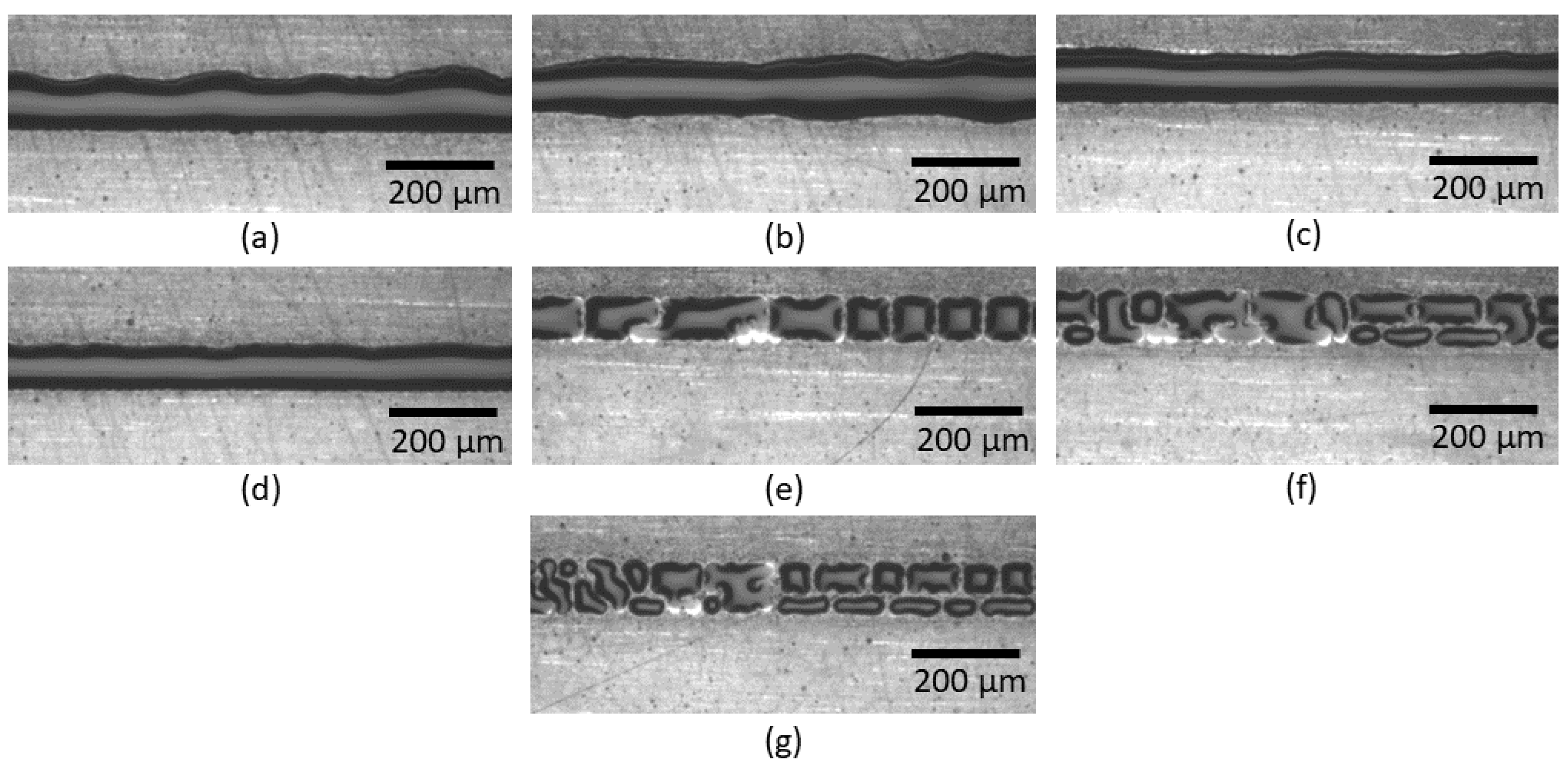
The ideal drop spacing value of 45
was selected after performing line tests of different drop spacing values (30–60
) as illustrated in
Figure 3.
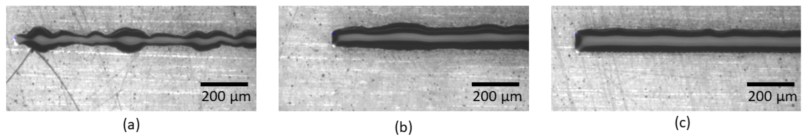
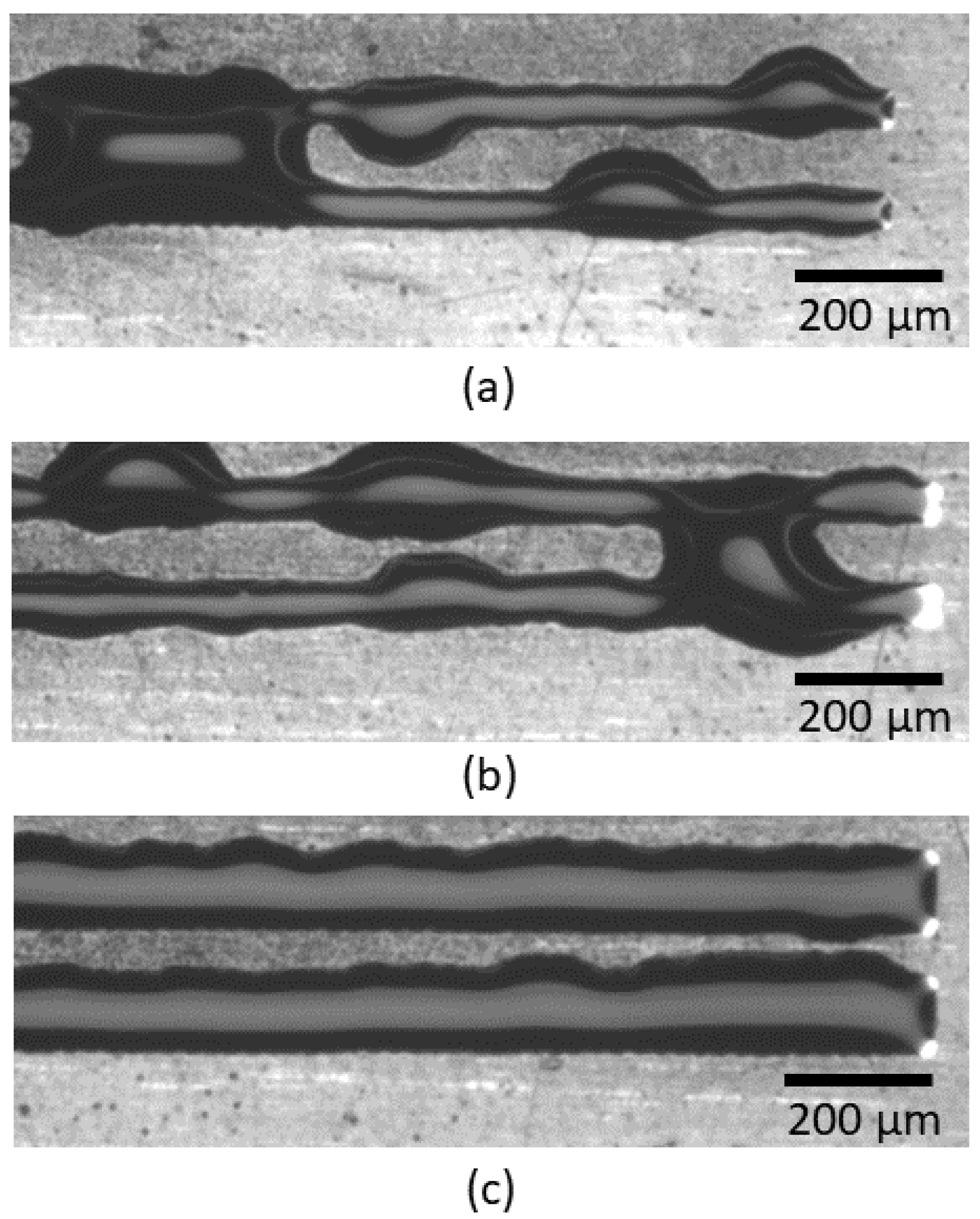
Also, different track widths of 50, 80, and 110
were tested and the ideal value was 110
as shown in
Figure 4.
Next, two line tests were performed to find the best gap size between two tracks of width 110
. The tested gap sizes were 50, 80, and 110
. The most suitable gap size that does not allow the two lines to overlap is 110
as seen in
Figure 5.
2.3. Microheater Fabrication
Polyimide (PI) Upilex-50S is chosen as the microheater substrate at a thickness of 50
. The advantages of PI include it being chemically inert to solvents used in printing solutions and having good mechanical stability [
13,
25]. It is especially suitable for printing microheaters due to its stability at higher temperatures, approximately 400 °C, and its low thermal conductivity, 0.26 W/(m·K) [
3,
4,
6,
25].
Standard protocol of wet cleaning was used to clean the substrate. It was submerged in isopropanol for 5 min and then it was rinsed for 5 min with deionized water. After that, it was left to dry in dry air followed by dehydration in an oven at 120 °C for 10 min. Finally, the surface of the PI substrate was activated with the UV ozone cleaning system (Osilla) for 2 min at 22 °C.
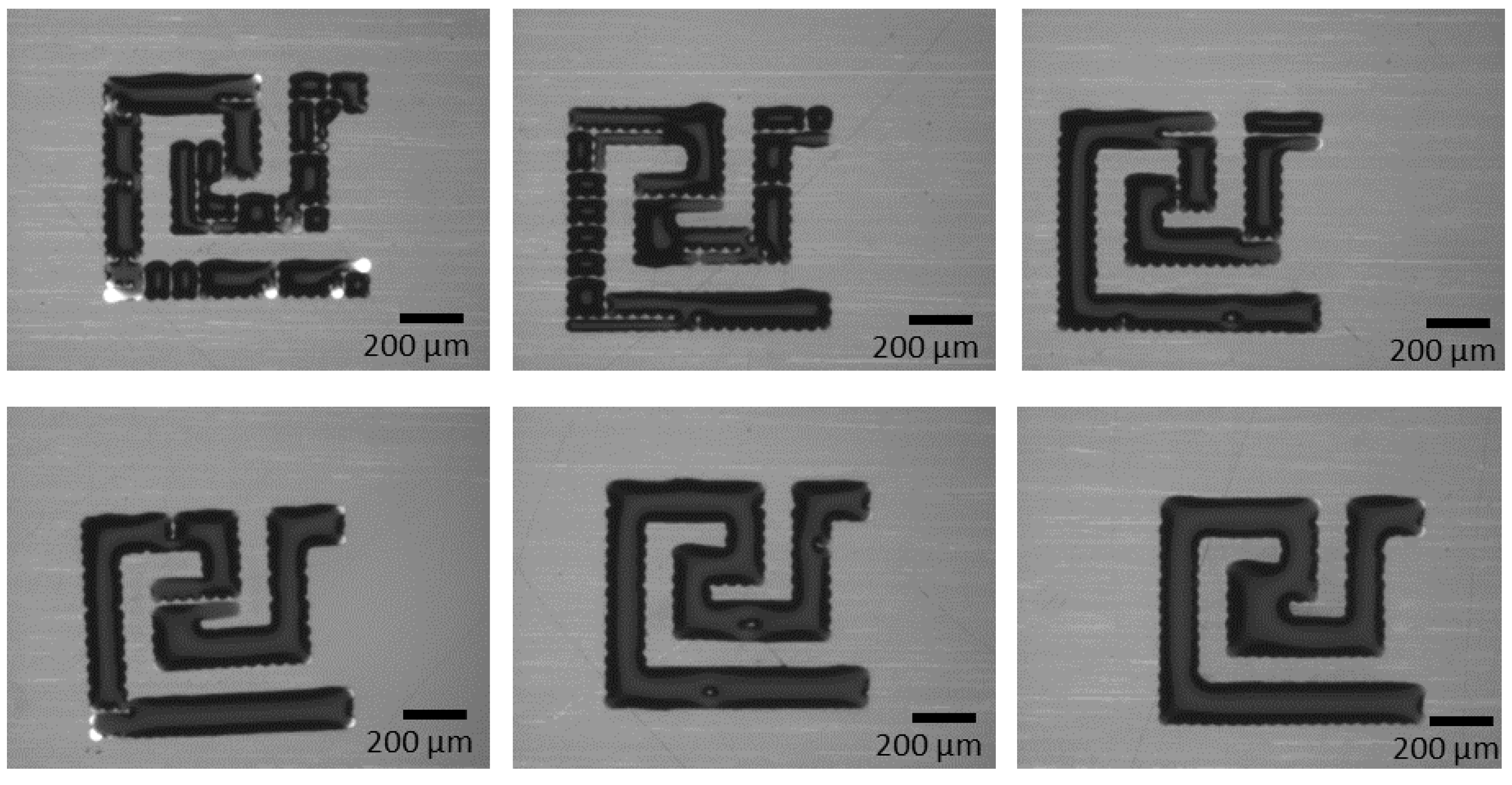
Sometimes the substrate does not get activated enough and needs to be inserted into the UV device for more time. The
Figure 6 shows six different stages of activation while increasing 20 s for each stage.
Ideal physical and electrical properties are determined by the quality of the printed Ag patterns [
2]. The track width of the double meander microheater pattern is 110
with gap width of 110
in between the tracks. The patterns were printed repeatedly without any significant differences.
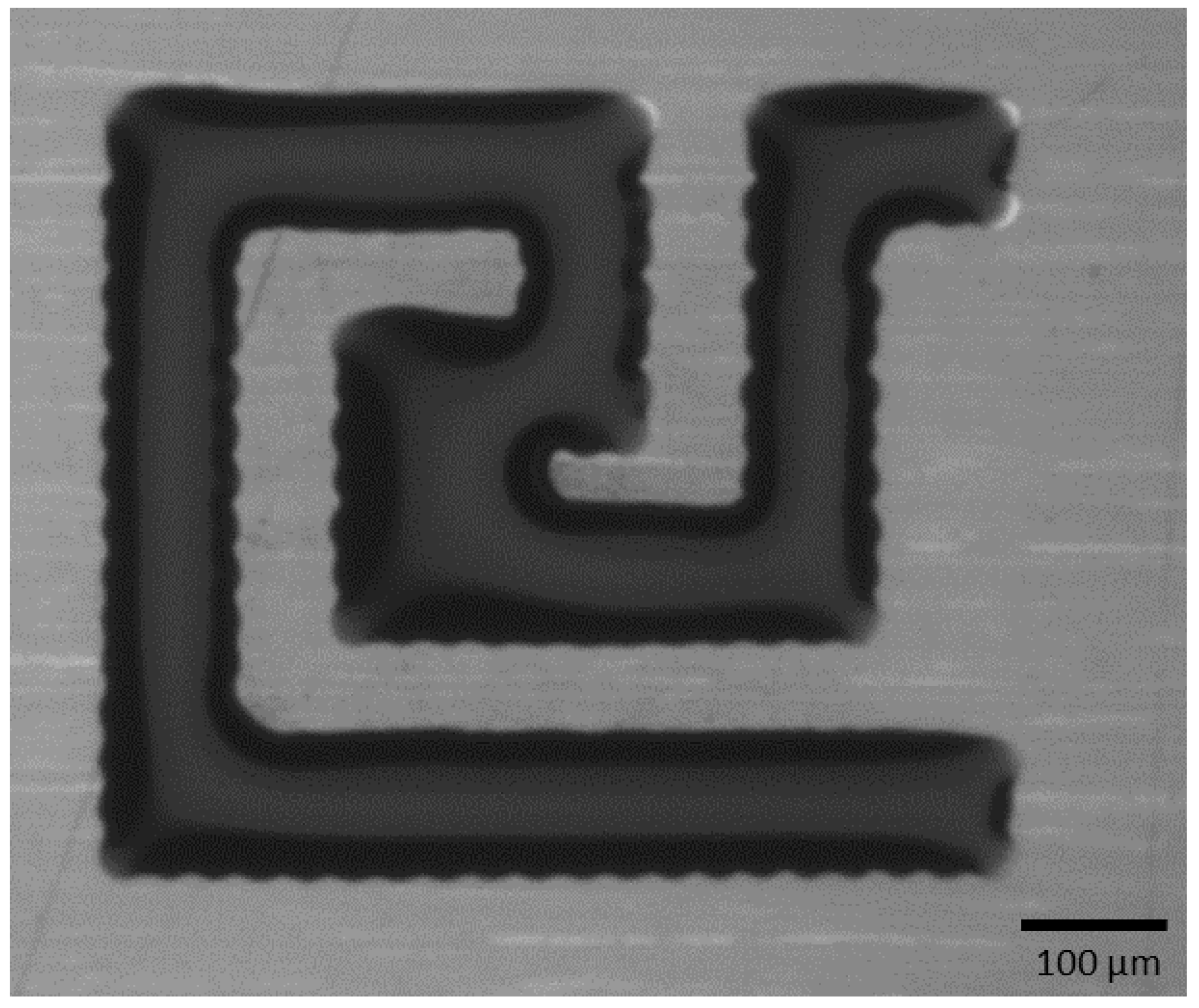
The double meander microheater was printed with only one cycle whereas the interconnect part was printed with three cycles. The three cycles ensured no gaps in the printed interconnects and therefore increased the electrical conductivity when testing the resistivity of the microheater. One printing cycle of the interconnects was tested and it was not conducting at all. On the other hand, printing multiple cycles increases aspect ratios of the printed microheater in addition to increasing the width of the printed tracks and them having irregular edges. This was not an issue for the scope of this work as the gap between the tracks was large enough to overcome this problem. The single pass printed microheater is shown in
Figure 7.
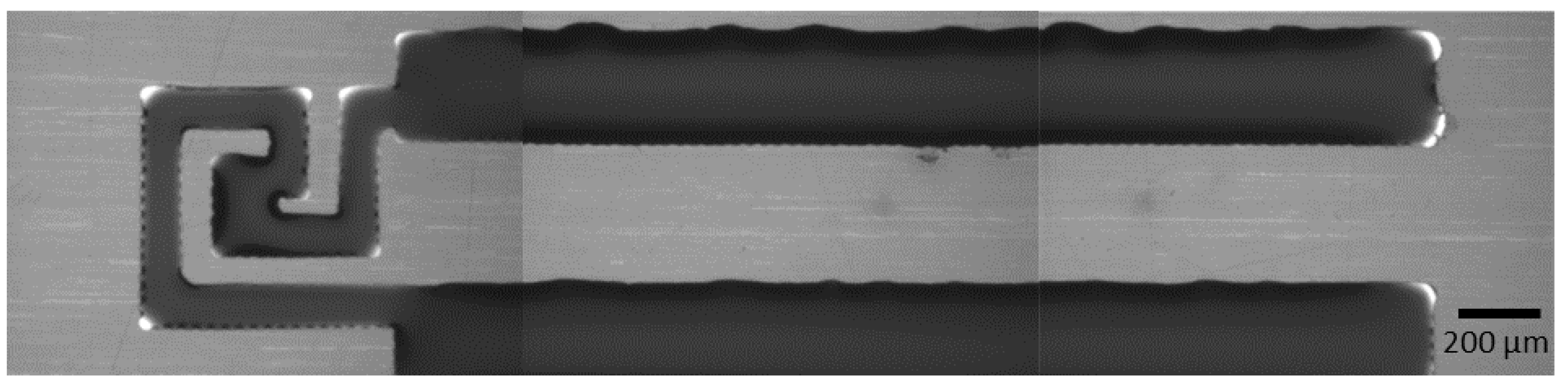
Then Three passes of the interconnects were printed as seen in
Figure 8.
The recommended sintering temperature for this ink is around 120 °C, which is suitable for PI substrate [
25,
26]. Finally, the printed microheater was sintered in the oven at 120 °C for 1 h [
26]. The increases the adhesion of the Ag ink to the PI substrate and evaporates any extra surfactant material that is mixed with the Ag ink.
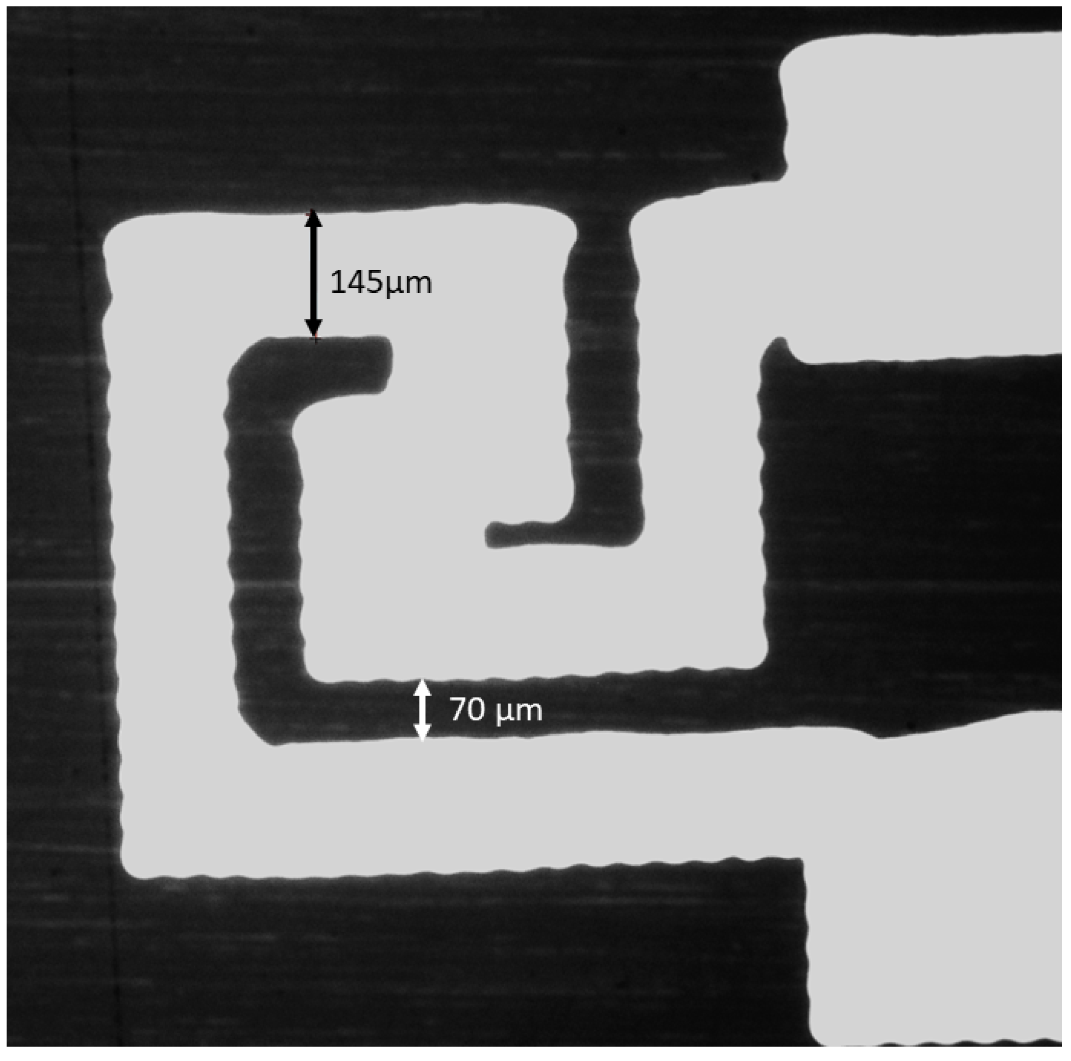
Images of the microheater after sintering are illustrated in
Figure 9. They show a track size of 145
which is greater than the simulated track size of 110
, and gap size of 70
, which is less than the simulated gap size of 110
. This is due to the spreading behavior of Ag ink.
The pads required for microheater measurements are drawn manually with silver ink and then sintered in the oven for 30 min. The pads’ part was inserted into a zip connector to perform the resistance measurements using a multimeter.
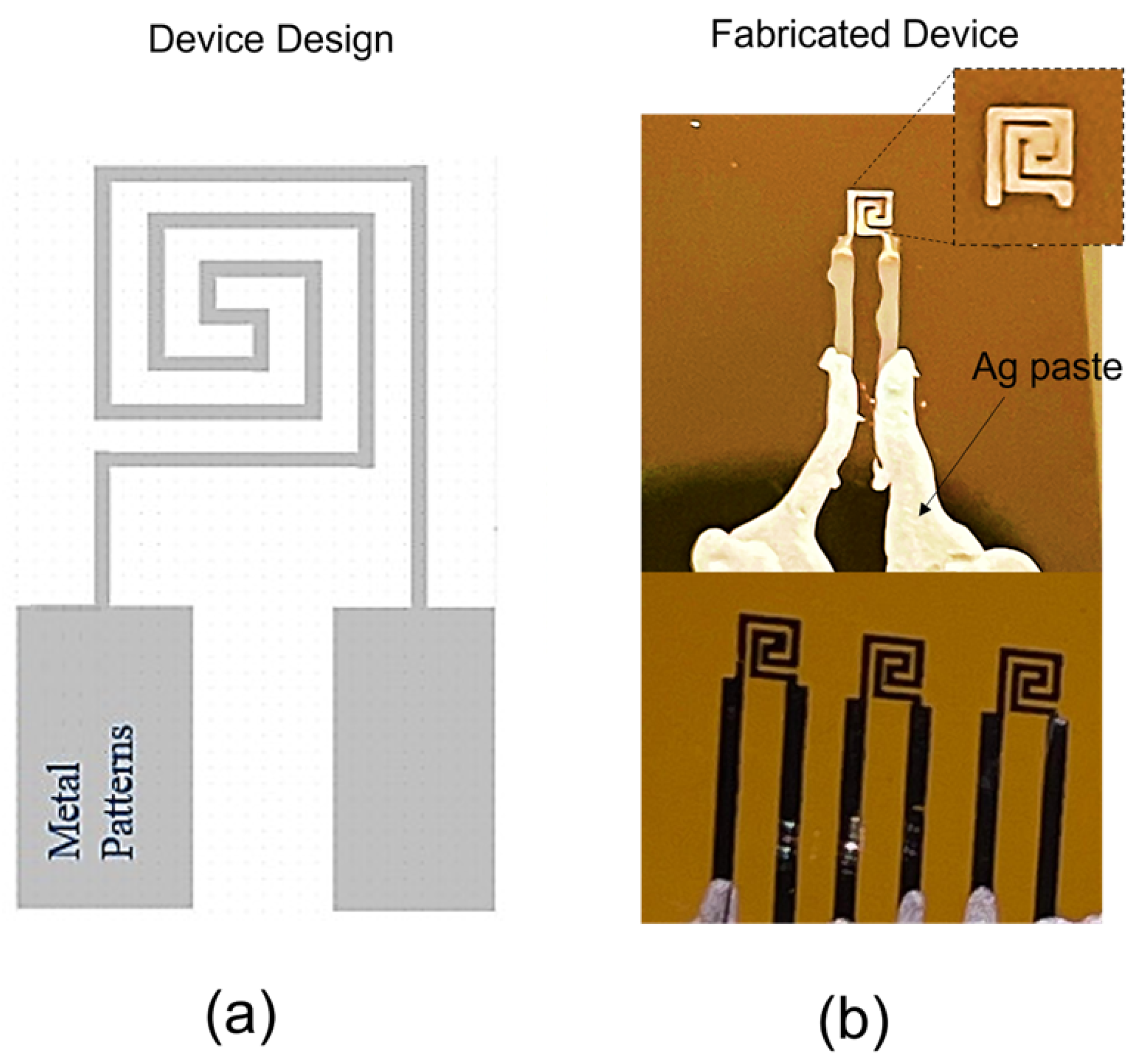
Figure 10a shows the geometrical design of the microheater designed in COMSOL with the connecting pads.
Figure 10b shows a microscopic image of the fabricated microheater on a PI substrate. Bottom inset of the
Figure 10b shows 3 different microheaters fabricated through inkjet printer on the same substrate, they are uniformed in morphology. The proposed optimized process can be used for producing microheater with good repeatability and yield.
The electrical resistance of the 110 wide Ag patterns were measured between the two printed pads connecting the microheater and found to be 119 Ω which is close enough to the simulated value of 100 Ω.
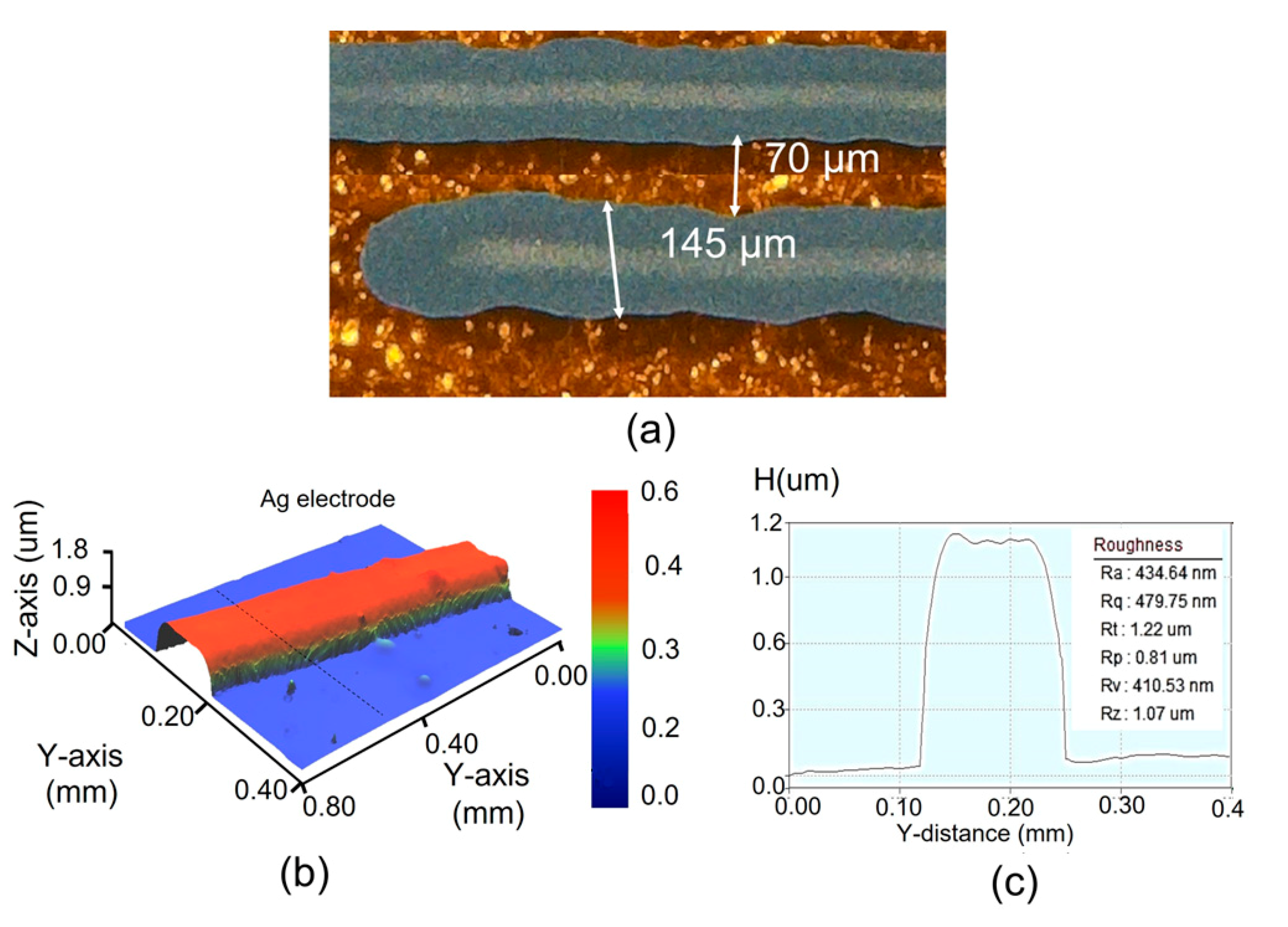
Figure 11a shows a microscopic image of the printed microheater lines on a PI substrate. Images shows a continuous and uniform lines that confirms the conductivity of the silver printed lines. Average thickness of the silver line after sintering is 145 μm whereas the clearance between two conductive lines is around 70
.
Figure 11b shows the 3D nano-profile image of the silver printed line over a PI substrate. The height of the silver line is around 500 nm. In this 3D nano profile image, the silver line is continuous and uniformed.
Figure 11c shows the roughness analysis of the silver line, the average roughness of the silver line is 450 nm, which is equal to the height of silver line.
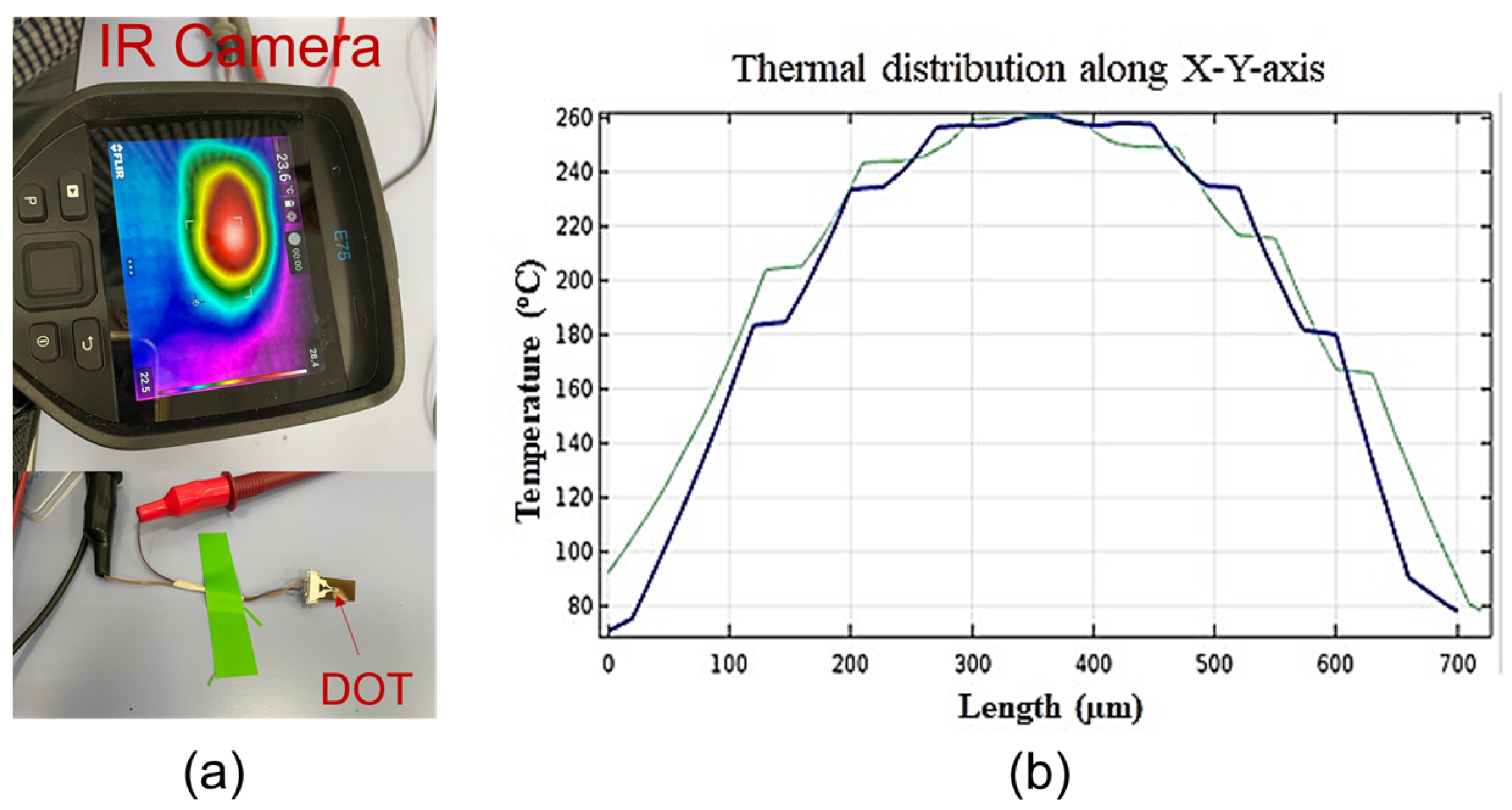
Figure 12a shows thermal characterization of the fabricated microheater by using IR camera. For this characterization, the microheater was connected to a power supply through crocodile connecters and placed the microheater on the plain desk. IR camera was shine perpendicular to the top surface of the microheater as shown in
Figure 12a. It was observed that the temperature at the center of the heater reaches up to 250 °C. This microheater can provide localized temperature to the devices such as humidity sensors to enhance their recovery time.
Figure 12b shows thermal distribution histogram of the microheater along the length of the device, around 350
the temperature is almost 250 °C.
Table 4 summarizes the state-of-the-art silver microheaters and compares them to the proposed microheater fabricated in this work. Byer et al. fabricated a silver microheater on polyimide substrate using inkjet printing. The operating temperature was 63 °C suitable for visually detecting antibiotic susceptibility from cells culture in situ. Although their work uses the same ink and substrate that we are using, they use a single meander geometry compared to our double meander geometry which is the most suitable to achieve homogeneous heating over the effective area and it consumes less power than the other geometries [
9,
19,
20].


