1. Introduction
Nowadays, inkjet printing technology has become more widely adopted by manufacturers due to its simplicity and flexibility. There is increasing demand for paper-based products, including in such areas as T-shirt printing, microchip production or personalized production, while meeting increasing quality requirements.
An image analysis study of ink–paper interactions was conducted by Fiadeiro et al. [
1]. It is important to identify variations in the interaction of ink and paper, manifested in the machine and cross directions of the paper (Mendes et al. [
2]). The influence of paper properties on the print quality of an inkjet printer is described by Bandyopadhyay [
3]. Skowronski [
4] analyzed the complexity of the interaction between ink and paper in inkjet printing and their influence on the properties of printed paper [
4]. The initial coating of the paper remains important. The interaction between offset ink and coated paper is described by Ström [
5]. Liu and Derby [
6] analyzed the droplet formation of inkjet printers using different printing ink properties and actuation strength (voltage). A physical experiment was carried out to determine the possibility of ejection of well-shaped drops without the formation of satellite drops. The influence of voltage parameters on the piezoelectric ejection process of ink droplets with different rheological properties was investigated and analyzed by Jiao et al. [
7].
The droplet ejection process in inkjet printers is modeled by a single dimension presented by Jiang and Tan [
8]. Droplet stability after ejection was analyzed by Zhong et al. [
9]. To control the formation of droplets, Wang and Chiu [
10] investigated data-driven models of droplet formation. To improve the print quality by increasing the dots per inch (DPI) of the piezoelectric inkjet printhead, the width and length of the nozzle chamber become smaller. In this situation, the formation of droplets with different waveform times was performed by Wei et al. [
11]. The printing quality is directly related to the print excitation parameters (Qiu-min et al. [
12]). They mentioned that the piezoelectric (PZT) driving system is an important part in inkjet printing equipment. The main function is to eject droplets of an ideal shape and volume at the correct velocity and without satellites to reach the surface at the intended location. A machine learning approach for predicting the maximum spreading factor of droplets upon impact on surfaces with various wettability’s were investigated by Tembely et al. [
13]. They found that machine learning algorithms can more accurately predict the experimental results of the maximum spreading factor. Increasing the quality of DoD inkjet drops was analyzed by Oktavianty et al. [
14]. They mentioned that it is necessary to establish a flexible waveform design for different fluid compositions. The influence of excitation on dynamic characteristics of piezoelectric micro-jets was investigated by Li et al. [
15]. They demonstrated that the direct coupling method proves to be an effective and feasible method to quantitatively simulate the fluid dynamic characteristics of the micro-jet. An evaluation of the relationship between interdigital geometry quality and inkjet parameters was analyzed by Bertolucci et al. [
16]. They developed a methodology for assessing the relationships between geometrical quantities and printing parameters. The effect of ink supply pressure on the piezoelectric inkjet was investigated by Kim et al. [
17]. They mentioned that decreasing the ink supply pressure can be expected to improve the stability and productivity of inkjet printing. Simulations and sensitivity analysis of piezoelectric inkjet printheads were provided by Nguyen et al. [
18]. They developed a lumped element model (LEM) for an inkjet head to simulate its droplet generation in inkjet printing. The inkjet printing of PEDOT:PSS-based conductive patterns for 3D forming applications was investigated by Basak et al. [
19]. They developed a polymer PEDOT: PSS-based ink formulation that was inkjet printable through a 21 µm orifice. The effect of process parameters on the performance of drop-on-demand 3D inkjet printing was analyzed by Elkaseer et al. [
20]. They developed an optimization-oriented simulation tool of droplet behavior during the drop-on-demand 3D inkjet printing process.
In this paper, we perform numerical simulation using the COMSOL multiphysics finite element method and analyze the ejection of droplet through a nozzle into the air, the shape turnover of droplet, and the distribution of satellites during the fall. Inkjet printing inks are calculated as Newtonian fluid. The flow of ink is modeled by the Navier–Stokes equations for an incompressible fluid. The simulation model presented is solved using the level set method to determine the ink–air interface.
2. Problem Formulation
There are many inkjet printers that use inkjet printheads that move in one direction, making the printers easier to use. The print material is moving in the opposite direction of the printhead.
It can also be noted that there are many articles (Introduction section) on similar topics related to inkjet printing, and these topics remain relevant, leading not only to improvements in the printing process itself, but also to such fundamental things as the fundamental behavior of a liquid drop during its formation, movement into air and interaction with a solid surface.
Our study is characterized by the principles of numerical simulation and aspects of their optimization; when using finite elements, we study the chamber of the nozzle of the inkjet printhead, the ejection parameters, the fall of the droplet on the surface and the impact on it. In addition, similar inkjet printing processes are investigated by Elkaseer et al. [
20] and Wilson et al. [
21].
Elkaseer et al. [
20] are investigating inkjet printing technology as an alternative manufacturing method for producing functional parts from multi-material, such as micro-schemes.
They simulated and investigated the printing process, which takes into account the effects of droplet volume, droplet center-to-center distance, jetted droplets coverage percentage, ink–solid substrate contact angle, and overlapping droplets coalescence performance, as well as the number of printed layers. The simulation tool was created using the MATLAB programming language. The simulation results were experimentally validated, and the results showed good agreement with the maximum deviation for the horizontal features. The method they developed was used to find out the effect of processed TIFF image resolution and droplet diameter on the dimensional accuracy of inkjet 3D printed parts [
20].
For our further research, it is useful to use a geometric-based approach to simulate the coalescence of droplets on a substrate, taking into account the resolution and percentage of coverage of the printed image file and the droplet diameter.
Wilson et al. [
21] studied inkjet process optimization for a laboratory inkjet printing system designed to print with polymer inks, with a focus on transparent and electrically conductive polymers. In this study, the authors investigated the speed of droplets from a nozzle as a function of the input voltage waveform and dwelling time difference. With the correct ejection parameters, the authors obtained a continuous line from droplets on the polymer surface. This study [
21] presents a new model incorporating the effects of inertia, surface tension, and ink viscoelasticity. Due to the increased viscosity of the ink at low rates, the ink becomes more shear thinning. These studies can be used for our further research on the similar effect of inks on the inkjet process.
It should be noted that when using COMSOL Multiphysics to conduct a numerical experiment, it is necessary to determine the detailed paint parameters. The corresponding geometric parameters of the head are also important. Several of the referenced publications [
20,
21] do not use COMSOL Multiphysics, so comparing the results may be one of the future tasks.
3. Methodology
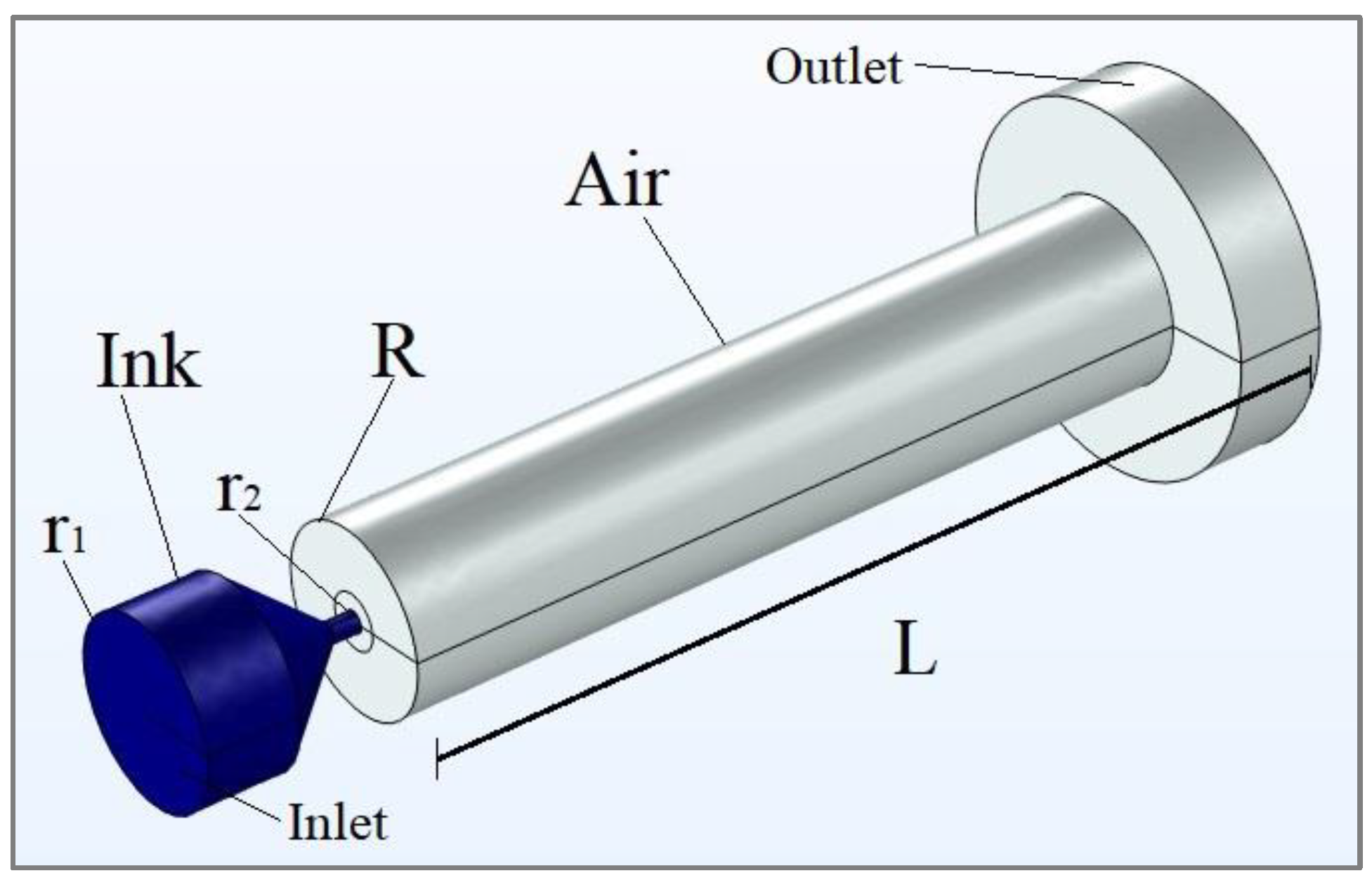
Based on standard PZT printhead models, a single inkjet printhead nozzle chamber was modeled using COMSOL Multiphysics software. The geometry of the three-dimensional numerical model of the inkjet printhead nozzle is shown in
Figure 1.
A droplet is formed by jetting a fixed amount of ink into an air-filled cylindrical printing chamber with a length and a radius The radius of the jetting channel is equal to . The initial circular shape and the cross-sectional radius of the droplet are predefined by the channel shape and size.
The waveforms are generated by the top inlet of the nozzle by applying the fluid intake velocity and various waveform dwelling times. Different waveforms dwelling times are shown at
Figure 2.
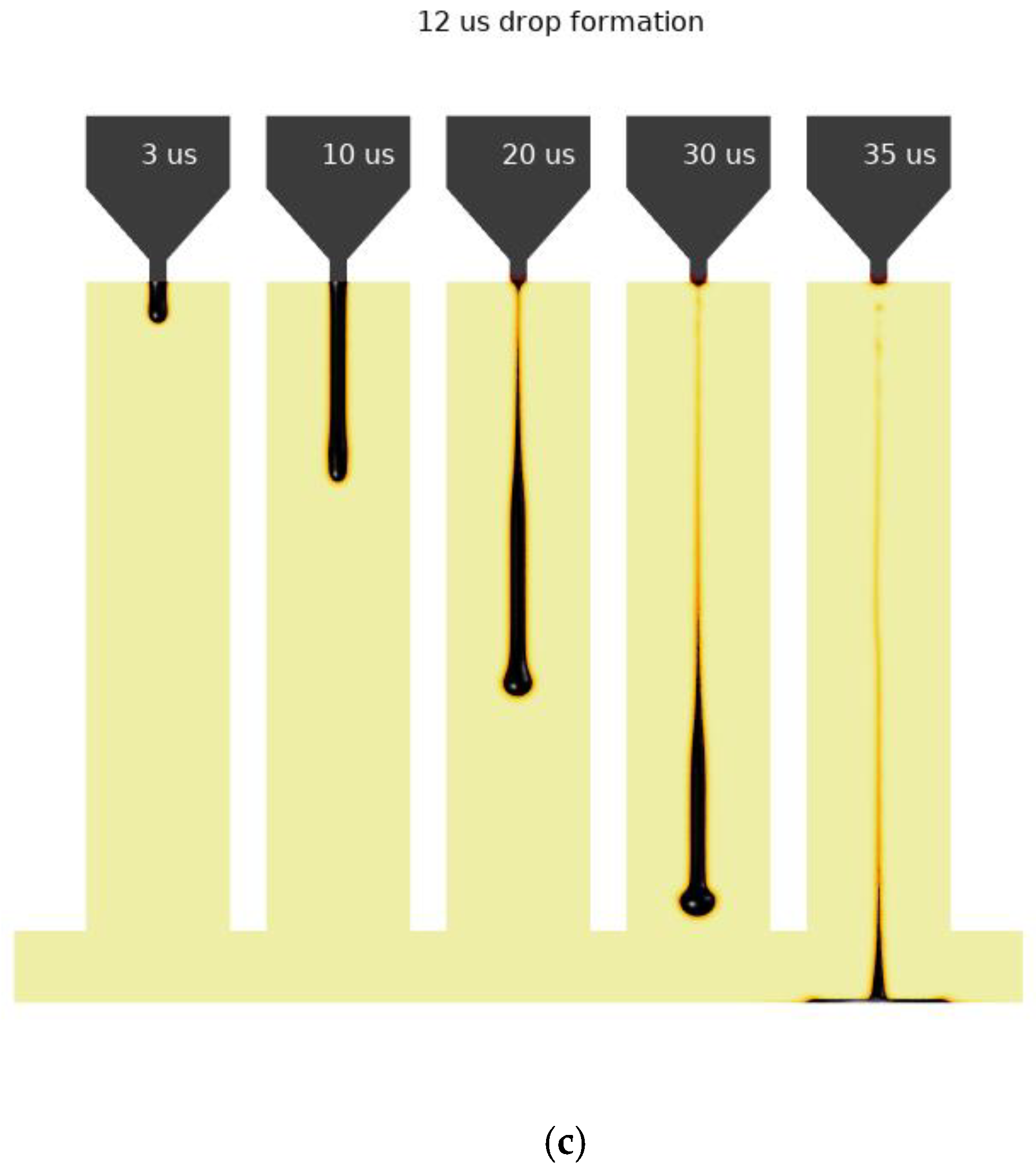
Here, the printhead was actuated by an optimized waveform with different dwelling times , , and The considered droplet ejection times were set to demonstrate differences in droplet behavior. Typically, PZT inkjet printheads use different dwelling times to control droplet size on the surface. To better understand the droplet behavior and impact differences, we chose the different dwelling times mentioned above. As the results will show, these are the time intervals when the droplet formed on the printed surface has a surface close to the shape of a hemisphere, with a dwelling time of 1 µs, and the spherical surface of the droplet is completely lost with a dwelling time of 12 µs; an additional intermediate dwelling time interval was chosen to be 3 µs. The ink inlet velocity was When the pressure waveform appears, the liquid begins to push out the ink through the printhead nozzle, forming the jet. Then the jet pinches off from the nozzle, the main droplet begins to form, and peripheral satellites may appear.
Numerical simulation based on the continuity equation and the N–S equation reconcile two-phase flows of incompressible substances. The continuity equation for an incompressible fluid is calculated using the following equation:
Here, ∇ is the vector differential operator, and
u is the fluid velocity. From the definitions of calculus, we know that the gradient operator (∇) is calculated by the equation
where
i,
j,
k are the unit vectors in the directions of the x, y and z coordinates.
The N–S equation describes the momentum conservation equation for a viscous incompressible fluid in motion. This equation is written as follows:
Here, is the substance density; is the substance viscosity; is the pressure; and is the acceleration due to gravity.
The following equation describes the interface between the ink and air phases. The convection of the reinitialized level set function is written as the following:
Here, the coefficient represents the level set interface between ink and air. Accordingly, represents the air environment, and represents ink. In the transition layer close to the interface, smoothly changes from 0 to 1. The fluid velocity, , represents the motion of interface during the environments interplay. The parameter determines the amount of stabilization of the level set function. A suitable value for is the maximum magnitude occurring in the velocity field.
By default, this reinitialization parameter for the current simulation is set to Here, ε refers to the thickness of the transition layer. For this simulation, ε is taken as half of the representative mesh size in the area that the falling droplet passes through. For this simulation, the interface thickness is controlled by the default and set to 1.25 µm.
By defining the interface of different substrates, the level set function is used to stabilize the density and viscosity calculations through the interface. In numerical simulation, it is necessary to take into account the dynamic viscosity (shear viscosity)
. It describes the interface between the shear rate and shear stresses in the substrate. The substrate density and dynamic viscosity in different finite elements depend on the interface coefficient
. Density and dynamic viscosity are written as follows:
Here, indicates the air density and indicates the ink density; indicates the air viscosity and indicates the ink viscosity.
In numerical simulation, ink and air are investigated as a substrate, from the flow of which viscous stresses arise at each point. The N–S equations describe the mass and momentum transfer of an incompressible fluid, including the surface tension and gravity forces. The motion of the droplet, taking into account the conservation of mass, is calculated from the following differential equations:
The surface tension force is calculated by the equation
Here, δ is the Dirac delta function; σ is the surface tension coefficient; ĸ is the curvature; and
n is the unit vector (normal direction). The unit vector is calculated from the following equation:
The delta function is approximated by the following equation:
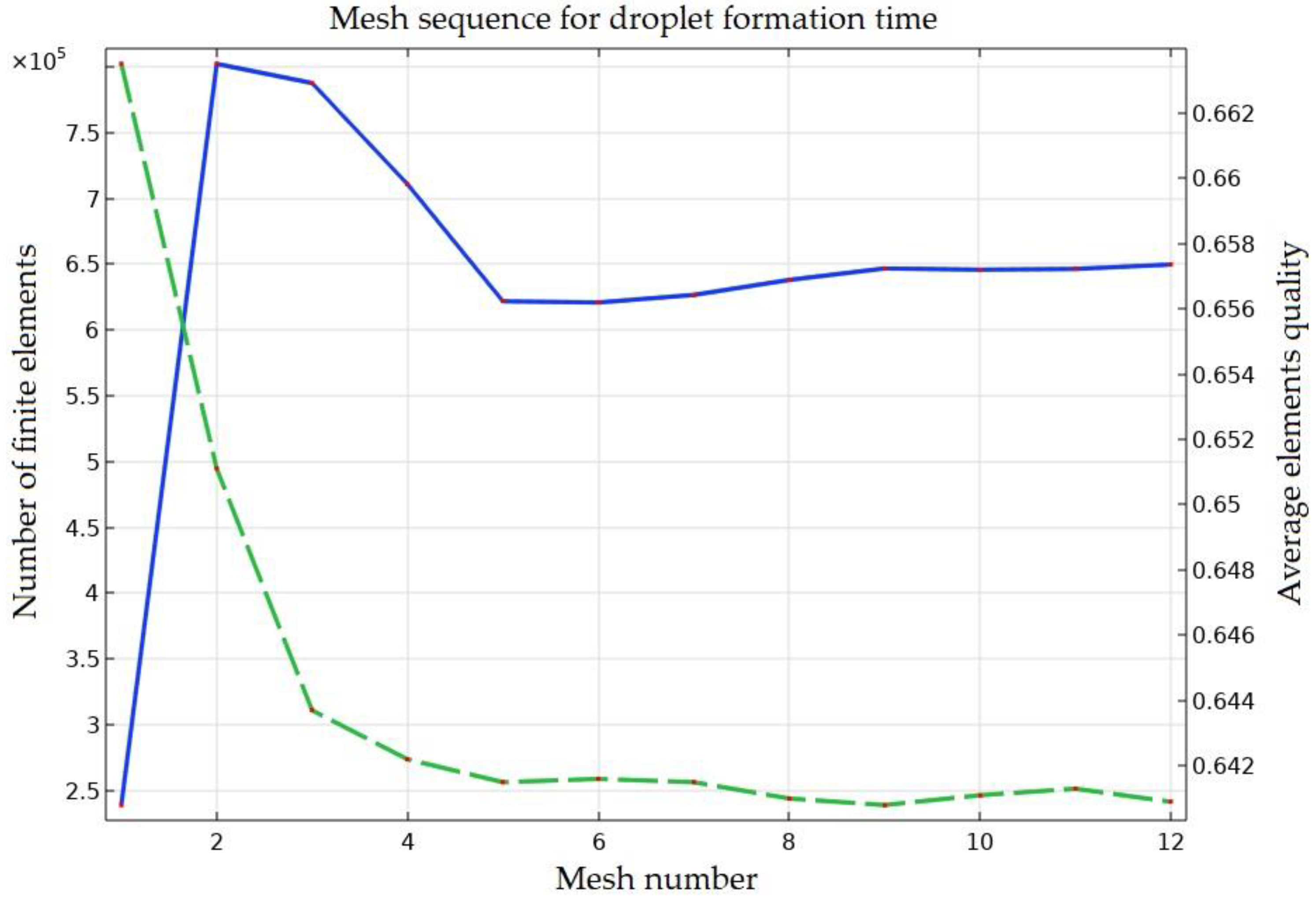
To calculate the droplet motion, including mass conservation, the adaptive mesh refinement function is used to locally improve the mesh at the ink–air interface. For this simulation, the finite elements sequence and turnover are shown at
Figure 3.
This functionality will essentially divide the simulation progress into several time intervals and locally refine the mesh in the region, where the phase interface is present in each interval to improve the accuracy of the calculation. To begin with, we have about 220,000 finite elements, and during the ejection, the mesh of the droplet changes 12 times. At the second mesh refinement, the number of finite elements reaches 800,000. The average quality of the elements decreases with an increase in the number of finite elements.
The final droplet mass can be calculated using the following COMSOL Multiphysics numerical simulation equation:
There are several dimensionless parameters that are very important to the inkjet printhead working process. The Reynolds number
determines the ratio of a fluid’s inertia to its viscosity, while the Weber number
determines the ratio of inertia to its surface tension (Seipel et al. [
22]). These dimensionless numbers are calculated using the following equations:
Here, is the droplet velocity and is the length of the nozzle diameter.
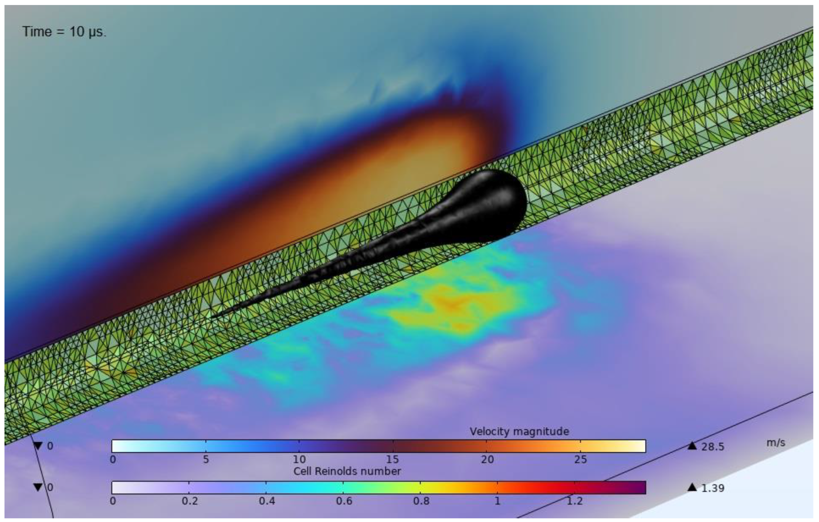
Several effects are observed during the motion of the ink droplet. A typical picture of a droplet, a fragment of the mesh and a contour plot of the velocity magnitude accompanied with the Cell Reynold’s number are shown in
Figure 4.
The influence of droplet velocity in the inkjet printing process can be eliminated by forming the Ohnesorge number
. There is a solution based on the N–S equations for expressing droplet ejection limitations considering the interfacial, viscous and inertial properties of the fluid (Seipel et al. [
22]):
The value can only be calculated from the physical properties of the inks and the nozzle size scale. It is independent of the waveform extraction impulse that controls the velocity. closely affects the behavior of an expanding droplet from a printhead nozzle.
The initial ink printability specification is required for ejection of stable droplets and should be in the acceptable range of 1 < Z < 10, (Fromm [
23]; Derby and Reis [
24]). If the number Z > 10, then during the printing process, satellite droplets will form, which degrading the print quality. If the number Z < 1, then the viscous forces of the fluid will prevent the expansion of the droplet.
Proper operation of the printing process in a DoD inkjet printhead requires a propriate combination of physical parameters, which will also depend on the droplet size and velocity (via the Reynolds or Weber number value). The results entail empirical data that are embedded in numerical simulation calculations based on the dimensionless numbers We, Re and Z.
4. Experiment and Results
The physical parameters of ink and air used in numerical simulation of the inkjet printhead nozzle are presented in
Table 1.
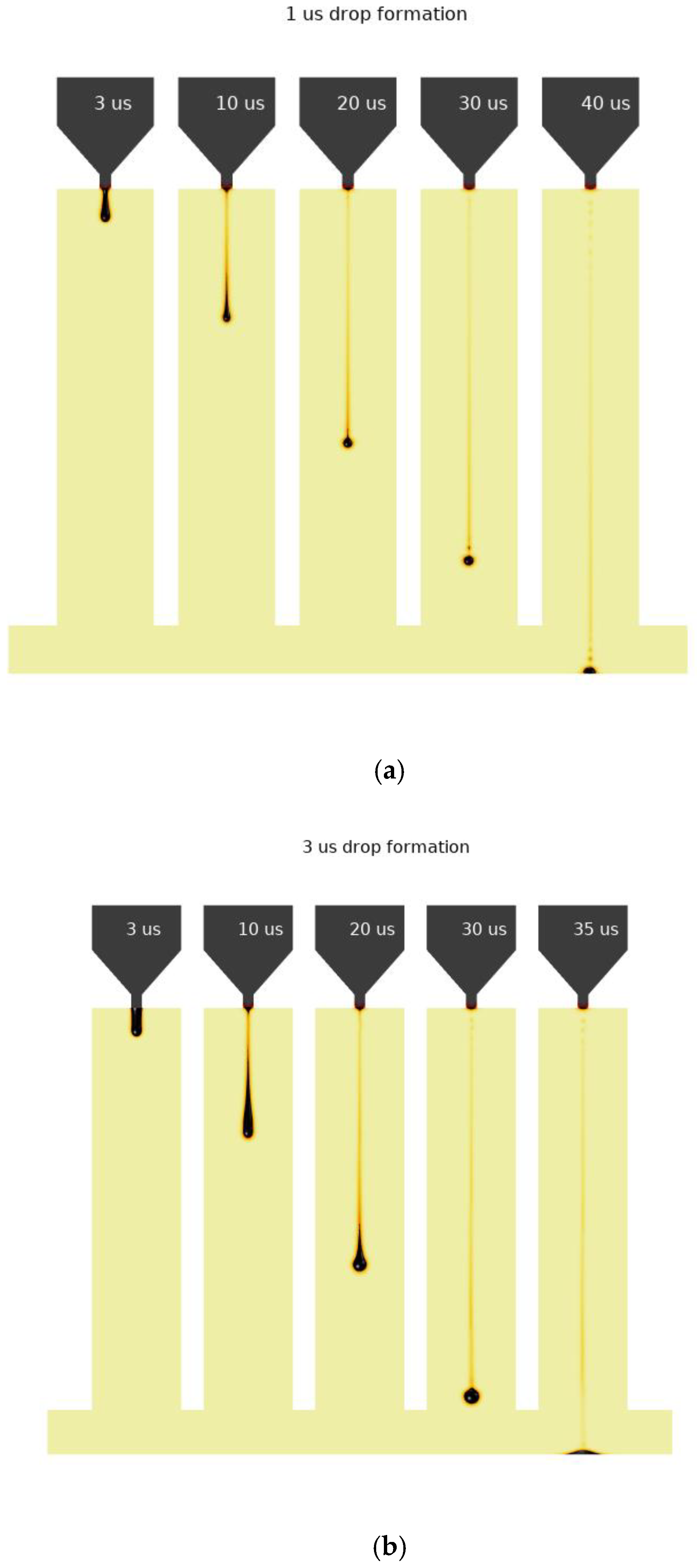
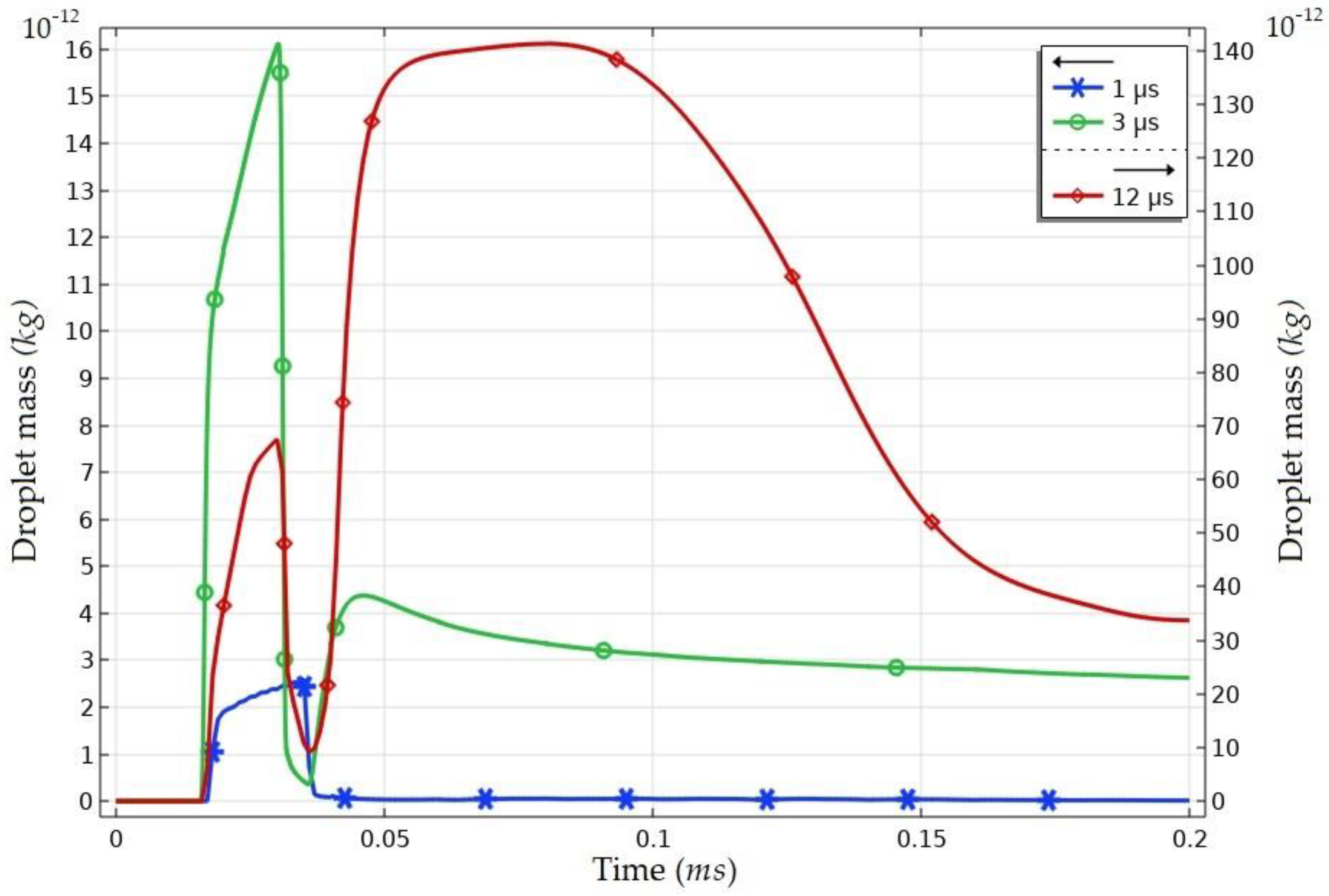
The droplet ejection progress was taken from numerical simulation using COMSOL Multiphysics software. The momentum strength of the droplet ejection is predicted from the different velocity at the fluid inlet. For these simulations, the inlet velocity was set to 0.5 m/s. The presented graphs with different waveform dwelling times are shown in
Figure 5.
When the dwelling time is 1 µs, the final mass of the droplet is 2 × 10⁻¹³ kg. The droplet forms a geometrical surface close to a hemisphere after the pitch off the nozzle and reaches the surface approximately 40 µs from the start of actuation. After increasing the dwelling period to 3 µs, the mass of the droplet increases to 3 × 10⁻¹² kg. Larger droplets also form a geometrical surface close to a hemisphere and reach the surface faster by 35 µs. After increasing the formatting time to 12 µs, the droplet is ejected with a large tail and does not form a hemisphere when falling. After the impact with a surface, the droplet splashes and does not form the final round shape on the surface. The final mass before droplet impact with a surface and splashing is 1.4 × 10⁻¹⁰ kg.
The final mass of the droplet depends on the different dwelling time period. The mass turnover of droplets is shown in
Figure 6. Here, us and ng stand for microseconds (µs) and nanograms (ng), respectively.
For this research, we investigate the droplet mass formatting with different ejection times. During the droplet formatting periods, the droplet mass increases in accordance with the effect of the inlet velocity. After the waveform decreases, the droplet continues to move forward toward the surface and pitch off from the nozzle.
If the inlet velocity was too low, the droplet would shrink to the nozzle and not move forward to the surface, and the kinetic energy of the droplet would be too low. After the droplet reaches the surface, the droplet splashes and we can see a sudden change in the graph. For a large formatting time of 12 µs, we see that a large mass grows in after 35–40 µs. This is caused by splashing and the droplet jet replacing the main droplet.


